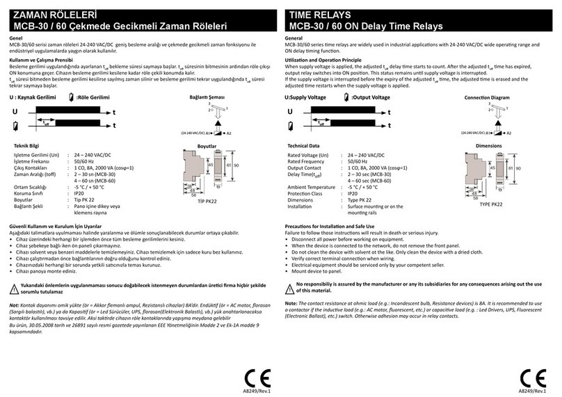
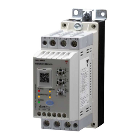
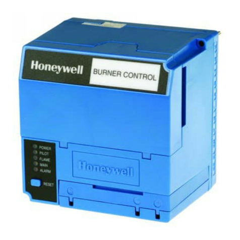
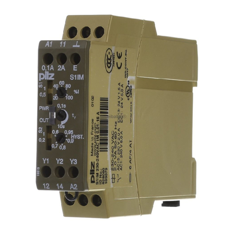
C&S CSDPR-V2-300 User manual

current Protection Relay
CSDPR-V2-300
R37QRG000132
QuickReferenceGuide
Q
R
G
This QRG will help you step-by-step installation, operation and programming
procedure. Please go through all the instructions carefully prior to implementing.
C&S Electric Limited

Introduction
In the family of protection relay, CSDPR-V2-300 is numeric multi powered Over-current
relay specially designed for ring main units & feeder protection. It combines the following
functions in one unit:
u Over current, Short Circuit, Earth Fault & Earth Fault High set protection
u DEFT & Inverse characteristics for O/C and E/F individually selected for
phase & earth fault
u Wide operating ranges of the auxiliary supply voltage (AC/DC)
u Remote trip *
uSwitch on to fault (SOTF) protection
u Remote protection block input DI*
u Potential pulse output for direct triggering the circuit breaker coil
u Potential free alarm contacts available
u Unbalance/ Asymmetric protection
u Circuit breaker failure protection
u Harmonic blocking (via DFT Filter) to avoid any unwanted tripping
u Two sets of setting groups
u Last 5 Fault and 10 Event record with Time stamp
u RS-485 Modbus
u USB port for PC / Laptop interface
Design
Relay will get energized from any of the following available sources:
u Aux. supply
u CT current
u Internal battery
u USB port
Relay will operate its trip contacts only when CT current is present or Aux. supply is available,
with other power sources, only the relay display/HMI will be available.
In the absence of Aux supply/Battery voltage/USB, LCD will get energized, if CT current is
10% of rated current or above. Trip coil will be operated, if CT current in single phase is at
least 20% of rated current or 15% of rated current in three phases. Relay is not powered from
Earth CT, so for earth fault protection, phase current is mandatory.
The disposal of our products and possible recycling of their components after
decommissioning has to be carried out by an accredited recycling company or
the products/components must be taken to applicable collection points. Such
disposal activities must comply with all local laws, guidelines and
environmental specifications of the country in which the disposal is done.
Our products and batteries must not be disposed of as household waste. For disposing
batteries it is necessary to observe the local national/international directives.
According to national legislation, penalties may be charged for incorrect disposal of
such waste.
By disposing of these products correctly you will help to save valuable resources and prevent
any potential negative effects on human health and the environment.
Disposal
02

Front Interface of the Relay
Description A : This key is used to ON the LCD when available source is Aux Supply, CT current or USB port)
Description B : This key is used to ON the LCD when available source is only Battery.
RESET
ON READY/HLTHY
TRIP
PICKUP
E3LL 1L 2 CBFPTCS
CSDPR-
V
2
ENTER
R M U R O T E C T I O NPE L A YR
Alpha Numeric LCD
Up Scroll /
Decrement Key
Enter Key
U S B port for P C /
Laptop communication
Fault Reset Key
(Manual Reset on
pressing for 2 sec)
See Description B
MHT Ready /
MHT Ready LED
Down Scroll /
Increment Key
Battery Cover
(Remove battery cover
to change the appropriate
battery)
See Description A
L1 phase for pickup & Trip indicator
L2 phase for pickup & Trip indicator
L3 phase for pickup & Trip indicator
Earth fault for pickup & Trip indicator
Common pickup for fault
Trip Status of Relay
Trip circuit supervision
CBFP external breaker failure indicator
TRIPE PICKUP3L
L
1L2 TCS CBFP
*
03

Conn. Diagram (TCS Model) *
NOTE: While doing the HV test, don`t connect the MHT terminal (C4-C5),
as internal capacitor bank could be in charged state & it can harm the circuitry.
In TCS model : Remote Trip & Remote Block DI will not be available.
L1
L1
L2
L2
L3
L3
P1
P1
P2
P2
S1
S1
S2
S2
IL1
IL1
E1
E1
E2
E2
IL3
IL3
E5
E5
IL2
IL2
E3
E3
E7
E7
E8
E8
E9
E9
E10
E10
E4
E4
E6
E6
Ie
Ie
A9
A9
A10
A10
A11
A11
DI-2
DI-2
DI-(Comm)
DI-(Comm)
DI-1
DI-1
* CB Open
* CB Close
B1
B1
B3
B3
B2
B2
B4
B4
Flag Indicator
Flag Indicator
Trip Coil
Trip Coil
TF+
TF+
TC-
TC-
TF-
TF-
TC+
TC+
DO-1
DO-1
A7
A7
A8
A8
DO-2
DO-2
A5
A5
A6
A6
Latch
Latch
Operates with
only Aux supply
Operates with
only Aux supply
DO-3
DO-3
A3
A3
A4
A4
DO-4
DO-4
A1
A1
A2
A2
B8
B8
B7
B7
A
A
RS 485
RS 485
B
B
B6
B6
COM
COM
COM
COM
COM
COM
COM
COM
NO
NO
NO
NO
NO
NO
NO
NO
Aux Supply
A13
Aux-P Aux-N
A14
Aux Supply
A13
Aux-P Aux-N
A14
* Remote Block
* Remote Trip
Conn. Diagram (Standard Model without TCS) In TCS model : Remote Trip &
Remote Block DI will not be available.
P1
P1
P2
P2
S1
S1
S2
S2
P1
P1
P2
P2
S1
S1
S2
S2
04

Dimension Details (All the dim. are in mm)
Front View
Side View
110.0
158.0
167.8
118.0
128.0
158.0
167.8
Specification Table of the Relay
* ordering based
Function ANSI CSDPR-V2-300
3 Phase Over current protection 51 ü
3 Phase Instantaneous protection 50 ü
Earth time Over Current 51N ü
Earth time Instantaneous Over Current 50N ü
Circuit Breaker Failure protection 50BF ü
Switch onto fault SOTF ü
Trip circuit supervision * 74TC ü
Fault Record – 05
Event Record – 10
LCD Display – 16x2 Alpha Numeric
Digital Input *
Remote Trip* / CB Close – ü
Remote Block* / CB Open – ü
Digital Output – ü
Pulse Output – ü
Powered Nature – CT powered
Aux. powered
Front Communication – ü
Rear Communication (RS-485) – ü
Battery Backup – ü
05

Back Terminal view (TCS model)
Back Terminal view (Standard model without TCS)
RemoteBlock(DI-2)
RemoteTrip(DI-1)
DI-Common
06

Remove the Battery cover
by twisting it on the left side
as shown in the Left image.
Close the Battery cover by
twisting it on the right side
as shown in the Left image.
Remove the Sticker placed
on Battery to start the unit
with Battery.
Replace the prescribed
1/2 AA size suitable battery
with the new one.
Battery changing Procedure Photograph shown here for have an idea only
07

Technical Data
Rear (RS-485) Communication Setting
Parameter Display Setting Range
Slave Address SLV Add 1-32
Baud Rate BD Rate 9600/19200
Parity Parity NONE/EVEN/ODD
General Data
Front (USB) Communication
Front Port: CSE protocol with CSE LIVELINK on mini USB cable type A/A
Measuring Input
Rated data Rated current IN (1A)
Frequency FN: 50/60 Hz
Measurement Measurement of Phase / Earth current starts from 5%
Rated auxiliary Universal L: (18V - 60V DC)
voltage UH H: (85V - 260V AC /
110V to 300V DC)
Rated supply for Normal voltage UN L: (18V - 60V DC)
DI input H: (85V - 260V AC /
110V to 300V DC)
Power consumption
of Aux supply Quiescent approx. 3W Operating approx. 6W
Dropout pickup ratio > 95 %
Phase / Earth VA Burden : (2.5VA @ Rated Current)
08

Accuracy
Tripping times DMT : + 5% of the setting value or +40 mSec
with pre-fault IDMT : Accuracy as per IEC-255-3 (2xIs to 20xIs)
For VINV / NINV/RI : + 5% or + 40 mSec
For LINV/EINV/HV-Fuse : + 7.5% or + 60 mSec
Pickup accuracy +5% or +10mA
Boot-up time in < 100 mSec; (Event recorder enabled : 20mSec extra)
self powered mode
Output Contact (Relay Specs)
Number of relays 4
DO contacts (DO: 1, 2) DO1 & DO2 are user programmable
configurable & available for I>, I>>, le> & Ie>>, CBFP,
only with Auxiliary supply Unbalance (U0>), Remote DI, all faults
Relay contacts: 3, 4 Latch type of DO common for all
(available in all models) protection trip
Max. breaking capacity 1250VA / 150W resistive
500VA / 90W inductive
Max. breaking voltage 400V AC, 125 VDC
Max. continuous AC current 5A
Thermal Withstand Capacity
Thermal withstand Continuously 2.5A
capacity 10s 15A
for In=1A 1s 80A
09

Inverse Graph Representation
Inverse Time characteristics
10

Default First Screen
Two group of Protection Setting are available in CSDPR-V2 relay. User can select
One Group as Active Group. For setting below are simple steps for configuration:
Default Password for settings : “ 4-Times Enter Key”
MAIN DEFAULT SCREEN PAGE:
The very first Screen of the HMI shows the Measured Primary Current for all the
phases based on CT ratio.
L1 : 0000.0 A
L2 : 0000.0 A
<Menu 1>
(EDIT/VIEW PARAMETERS)
By using
the
scroll keys
select the
desired
menu and
press
ENTER.
Press Key
FACTORY MODE Setting are not for the users.
How to do Settings
*
Note : - * Menu Model Dependent
# / #EDIT VIEW
< > : For Active Group Selection of ParameterGROUP SELECT
< > : Protection Related Parameter MenuPROTECTION
< > : Cold Load Protection MenuCOLDLOAD PRT
< > : Fault Record MenuFAULT RECORD
< > : Event Record MenuEVENT RECORD
< > : Programmable Relay Assignment MenuDO ASSGNMNT
< > : Programmable Relay Reset MenuDO RESET
< > : Trip TypeTRIP TYPE
< RST TRIP CNT > : Reset Trip count Menu
< > : Display Options MenuDISPLAY OPTN
<BATTRY STATS > : MenuBattery Status
< > : Output Trip Test MenuTRIP TEST
< > : Communication 485 MenuCOMMN SETTNG RS
< > : Load Default MenuLOAD DEFAULT
< > : Clock Setting MenuEDIT RTC
< > : Password Change MenuCHNGE PSWORD
< > : Factory Setting MenuFACTORY MODE
< > : Relay Version MenuRELAY VERSON
← BACK
11

# GROUP SELECT #
ACTIVE-GRP : GRP1
←BACK
On selecting GROUP SELECT by pressing ENTER
key, user can change the active group by using
ENTER and then scroll key.
Press Enter and If the user selects the YES option
then it will ask to enter the correct password or else to
go to the previous menu by selecting the other
options by pressing ENTER key.
From Menu-1:
From Menu-1: # PROTECTION #
CTRatio : 0001 : CT Ratio for primary current display
Frequency : 50Hz : Frequency characteristic
PhaseCh : DEFT : Phase over-current trip characteristic
EarthCh : DEFT : Earth over-current trip characteristic
l> : 0.20xIn : Over-current Pickup
ti> : 0.01 : TMS Over-current Setting
t> : 0.1s : DEFT Trip Time
l>> : 0.5xIn : Short Circuit Protection
t>> : 0.03 : DEFT Trip timing for SC Protection
Ie> : 0.05xIn : Earth Over-current Pickup
tie> : 0.01 : Inverse Trip Time
te> : 0.05s : DEFT Trip Time
Ie>> : 0.01xIn : Earth High-set Pickup
te>> : 0.05 : DEFT Trip timing Earth High
SOFTpk : DISABLE : SOTF pickup setting
Unbalnc : 5% : Unbalance
tUnblnc : 0.50s : Unbalance DEFT Trip Time
CBFP : YES : CBFP Supervision Time
tCBFP : 0.15s : CBFP Supervision Time
td_TCS : 2.00s : TCS Trip Time
←BACK
O n s e l e c t i n g
P R O T E C T I O N b y
pressing ENTER key.
User can see the list of all
the protection setting
parameter by using the
scroll keys.
Press ENTER to select
the desired Parameter &
use SCROLL keys to
Edit the selected one.
If the user change any of
the setting, It is required
to save the changes by
pressing ENT ER key
and than selecting YES
option, after that entering
the correct password to
save the setting or else
to go to the previous
menu by selecting the
o t h e r o p t i o n s & b y
pressing ENTER key.
12

From Menu-1:
On selecting COLD LOAD PRT by pressing ENTER
key, User can see the list of all the parameter by using the
scroll keys.
Press ENTER to select the desired Parameter & use
SCROLL keys to Edit the selected one.
If the user change any of the setting, It is required to save
the changes by pressing ENTER key and than selecting
YES option, after that entering the correct password to
save the setting or else to go to the previous menu by
selecting the other options & by pressing ENTER key.
On selecting EVENT RECORD, by pressing ENTER
key, Event no. screen will appears. By using ENTER &
Scroll keys select the desired Event no. for its details. To
go to the previous menu press BACK key.
On selecting FAULT RECORD, by pressing ENTER
key, Fault no. screen will appears. By using ENTER &
Scroll keys select the desired Fault no. for its details. To
go to the previous menu press BACK key.
#COLD-LOAD-SET#
ColdLdPrt : DISABLE
tCldLoad : 00.10s
←BACK
# FAULT RECORD #
<FAULT NUMBER>
<ERASE FAULTS>
←BACK
# EVENT RECORD #
<SELECTION>
<EVENT NUMBER>
<ERASE EVENTS>
←BACK
From Menu-1:
From Menu-1:
From Menu-1:
On selecting DO ASSGNMNT by pressing ENTER key,
User can see the list of all the parameter by using the
scroll keys. Press ENTER to select the desired
Parameter & use SCROLL keys to Edit the selected
one. If the user change any of the setting, It is required to
save the changes by pressing ENTER key and than
selecting YES option, after that entering the correct
password to save the setting or else to go to the previous
menu by selecting the other options & by pressing
ENTER key.
# DO ASSGNMNT #
I> : DISABLED
I>> : DISABLED
Ie> : DISABLED
Ie>> : DISABLED
Unbaln : DISABLED
CBFP : DISABLED
TCS : DISABLED
AllFlt : DISABLED
SOTF : DISABLED
←BACK
On selecting DO RESET by pressing ENTER key, User
can see the list of all the parameter by using the scroll
keys. Press ENTER to select the desired Parameter &
use SCROLL keys to Edit the selected one.If the user
change any of the setting, It is required to save the
changes by pressing ENTER key and than selecting
YES option, after that entering the correct password to
save the setting or else to go to the previous menu by
selecting the other options & by pressing ENTER key.
# DO RESET MODE #
DO 1 : AUTO
DO 2 : AUTO
←BACK
13

From Menu-1:
# TRIP TYPE #
TripO/P : TRIP-COIL
←BACK
Reset Count....?
YES NO CANCEL
# DISPLAY-OPTION #
MODE : AUTO OFF
←BACK
On selecting TRIP TYPE by pressing ENTER key, User
can see the list of parameter by using the scroll keys.
Press ENTER to select the desired Parameter & use
SCROLL keys to Edit the selected one.
If the user change any of the setting, It is required to save
the changes by pressing ENTER key and than selecting
YES option, after that entering the correct password to
save the setting or else to go to the previous menu by
selecting the other options & by pressing ENTER key.
On selecting RST TRIP CNT by pressing ENTER key,
User can Reset the Trip count by selecting the YES
option or else comes out from the menu by selecting the
other option.
On selecting DISPLAY OPTN by pressing ENTER key,
User can see the list of parameter by using the scroll
keys.
Press ENTER to select the desired Parameter & use
SCROLL keys to Edit the selected one.
If the user change any of the setting, It is required to save
the changes by pressing ENTER key and than selecting
YES option, after that entering the correct password to
save the setting or else to go to the previous menu by
selecting the other options & by pressing ENTER key.
From Menu-1:
From Menu-1:
# TRIP TEST #
LED/DO TEST
BREAKERTEST
LATCHRESET
←BACK
# BATTERY STATUS #
BATTERY : OK
←BACK
On selecting BATTRY STATS by pressing ENTER
key, User can see the status of the Battery, whether it
is OK or NOT.
On selecting TRIP TEST by pressing ENTER key,
User can see the list of parameter by using the scroll
keys.
Press ENTER to select the desired Parameter & use
SCROLL keys to perform the test.
If the user selects any of the option it will ask to
continue the Test, If the user selects the YES option
then Right/Left key are required to press to perform
the Test, else select other option and press enter to go
to the previous menu .
From Menu-1:
From Menu-1:
14

From Menu-1:
On selecting CHNGE PSWORD Menu by pressing the
ENTER key, user will ask to enter the password. If the
user entered the correct password the next screen will
ask to Enter the New Password after that re-enter the
password for confirmation. If the password changed
successfully, it will flash password change message.
Enter Passwrd
New PASSWORD
Re-PASSWORD
SUCCESSFUL .!
PASSWD CHGD
From Menu-1:
# COMMN SETNG #
SLAVE ADD : 01
BAUDRATE : 9600
PARITY : NONE
←BACK
On selecting COMMN SETTING by pressing ENTER
key, User can see the list of all the parameter by using the
scroll keys.
Press ENTER to select the desired Parameter & use
SCROLL keys to Edit the selected one.
If the user change any of the setting, It is required to save
the changes by pressing ENTER key and than selecting
YES option, after that entering the correct password to
save the setting or else to go to the previous menu by
selecting the other options & by pressing ENTER key.
# EDIT RTC #
HOUR : 11
MIN : 26
SEC : 59
DATE : 23
MONTH : 08
YEAR : 2019
←BACK
On selecting EDIT RTC Menu, user can set the Date,
Month Year Day, Hour, Minute, Second by using the
S c r o l l k e y s .
Press ENTER to select the desired Parameter & use
SCROLL keys to Edit the selected one.
If the user change any of the setting, It is required to save
the changes by pressing ENTER key and than selecting
YES option after that entering the correct password to
save the setting or else to go to the previous menu by
selecting the other options & by pressing ENTER key.
CSDPR-V2-300-D
-L/H-P-T
Ver:V1.0.00.02
DN:220819
←BACK
From RELAY VERSION MENU:
On selecting RELAY VERSION Menu, by pressing
Enter key, it will show the screen.
User can see the relay information by using the scroll
keys. To go to the previous menu press BACK key.
Enter Passwrd
LOAD DEFAULT
Saving .........
On selecting LOAD DEFAULT menu by pressing
ENTER key, User will ask to Enter the correct password.
If the user enter the correct password, the default values
of the relays will restored.
From Menu-1:
From Menu-1:
15

C-60, Wing-A, Phase-II, Noida-201 305, Dist: Gautam Budh Nagar (U.P) INDIA Phone : +91-120-38748 00 / 01
C&S Electric Ltd.
(Protection & Measurement Devices)
For further information, please contact:
1800 572 2012
Technical Question or After-sales Service
Customer Center Quick Response
Service, Excellent Technical Support
Wrong measuring
& tripping values
Se t t i n g a r e n o t
g e t ti ng s a v e &
changed
Wrong connection/
Wrong CT Ratio
Wrong polarity of CT
Relay is in Trip/
Pickup state
Check the w iring as per
diagram.
Relay will not allow changing
its setting unless it is in
healthy state. There should
not be any pickup & present
fault should be
acknowledged. Press Reset
button & clear the entire fault.
Cause of Problem
Problem Remedy
Trouble Shooting Points
Digital outputs are
not operating
Aux Supply is not connected Two Digital outputs (Relays)
work only in presence of
Auxiliary supply. To recheck
the Digital output operation,
Go to Trip Test Menu, Enter in
the <LED/RLY TST> option &
test the Relays.
Tripping coil not
operating
W r o n g c o n n e c t i o n /
I n s u ff i c i e n t c u r r e n t t o
generate energy for Trip
1) Wiring to be checked.
2) Check whether the coil is
healthy.
3) Check the front Trip Ready
G r e e n L E D . I t s h o u l d
continuously blink. If it is not
blinking then relay can`t trip
the coil (insufficient energy
because of low current).
4) Use Trip Test to verify the
connection & relay operation.
Issue Date : 11.06.20, Rev. No : 05, Rev. Date : 18.05.22
Relay is not getting
on through Battery
1) Low Battery
2) Battery Seal is applied
1) P o we r O N t he re l ay
through Aux supply / current /
USB & go to battery status
menu, If Battery is low then it
display the Battery status
N O T O K . R e p l ac e t h e
battery
2) Check whether Battery
Seal is removed & both the
batteries are inserted with
proper polarity.
16
Table of contents
Other C&S Relay manuals

