Problembehebung DE
Carlo Gavazzi RSGT Troubleshooting Guide – Rev 1.0 10
Problembehebung
Prüfen, ob die FLC-Einstellung (Volllaststrom) nicht zu
viel höher ist als der Strom des Motortypenschilds.
Die Motorlast prüfen.
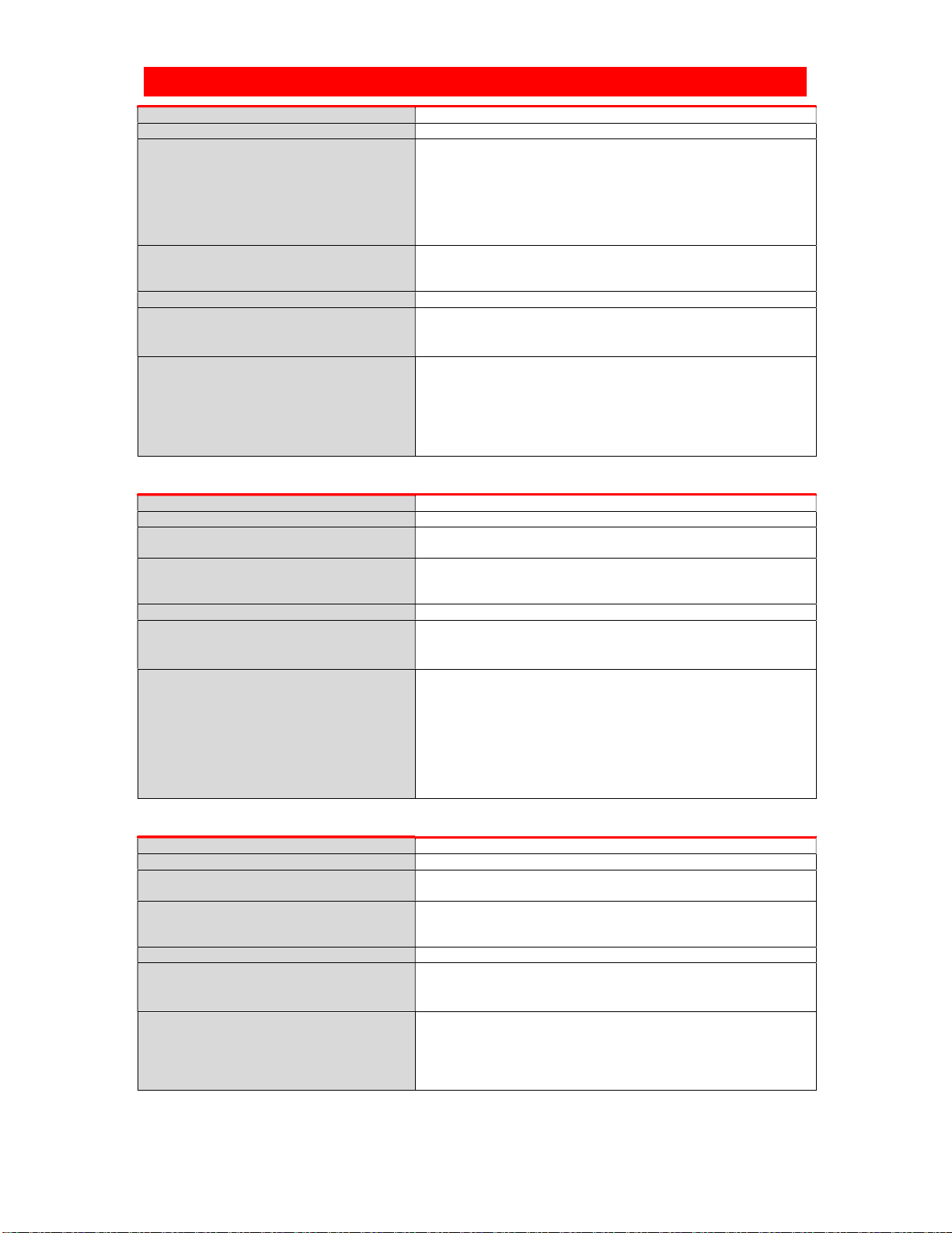
Alarm Überhitzung
Alarmbeschreibung
Das RSGT misst kontinuierlich die Temperatur des Kühlkörpers
und der Thyristoren. Wenn die maximale Innentemperatur
überschritten wird (für einen Zeitraum von mindestens 0,5 s), wird
ein Überhitzungsalarm ausgelöst. Dieser Zustand kann durch eine
zu hohe Anzahl von Startvorgängen pro Stunde, eine
Überlastungssituation beim Starten und/oder Stoppen oder durch
hohe Umgebungstemperaturen ausgelöst werden.
Alarmerholungsphase
Hängt vom Abkühlzeitraum ab.
(Wenn der manuelle Rücksetzmodus aktiviert ist, kann der Alarm
durch Drücken der Test-/Rücksetztaste beseitigt werden).
Das RSGT deaktiviert den Alarm erst dann, wenn die
nerhalb sicherer Grenzen liegt.
Aufeinanderfolgende Alarme für
5
Aktion zur Beseitigung des Alarms
Im automatischen Erholungsmodus wird der Alarm automatisch
deaktiviert. Die Erholungsdauer hängt von dem Zeitraum ab, den
das RSGT zum Abkühlen benötigt. Die Kühlzeitdauer fällt umso
länger aus, je höher die Umgebungstemperatur liegt.
Problembehebung
Stellen Sie sicher, dass die angegebene Anzahl von
Startvorgängen pro Stunde nicht überschritten wird.
Stellen Sie sicher, dass die Umgebungstemperatur um
das Sanftstartgerät herum innerhalb der zulässigen
Grenzwerte liegt.
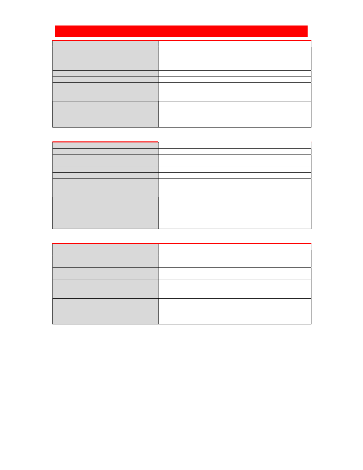
Alarm Überlast
Alarmbeschreibung
Der Überlastalarm wird unter folgenden Bedingungen ausgelöst:
Gemessener Strom > 1,05 × FLC beim Wechsel vom Anlauf zur
Überbrückung.
Laststrom > FLC. Die Auslösezeit variiert je nach Überlast-
Alarmerholungsphase
Hängt vom Abkühlzeitraum ab.
(Wenn der manuelle Rücksetzmodus aktiviert ist, kann der Alarm
durch Drücken der Test-/Rücksetztaste beseitigt werden).
Das RSGT deaktiviert den Alarm erst dann, wenn die
Aufeinanderfolgende Alarme für
5
Aktion zur Beseitigung des Alarms
Der Alarm wird nach 5 Minuten automatisch deaktiviert. Wenn der
manuelle Rücksetzmodus aktiviert ist, drücken Sie die Test-
/Rücksetztaste.
Hinweis: Lassen Sie dem Motor vor dem nächsten Startversuch
ausreichend Zeit zur Abkühlung.
Problembehebung
Stellen Sie sicher, dass die FLC-Einstellung mit dem auf
dem Typenschild des Motors angegebenen Strom
übereinstimmt.
Überprüfen Sie die Last auf Blockagen.
Wenn der Überlastalarm beim Anlaufen auftritt,
versuchen Sie, eine kürzere Anlaufzeit einzustellen, oder
erhöhen Sie die FLC-Einstellung.