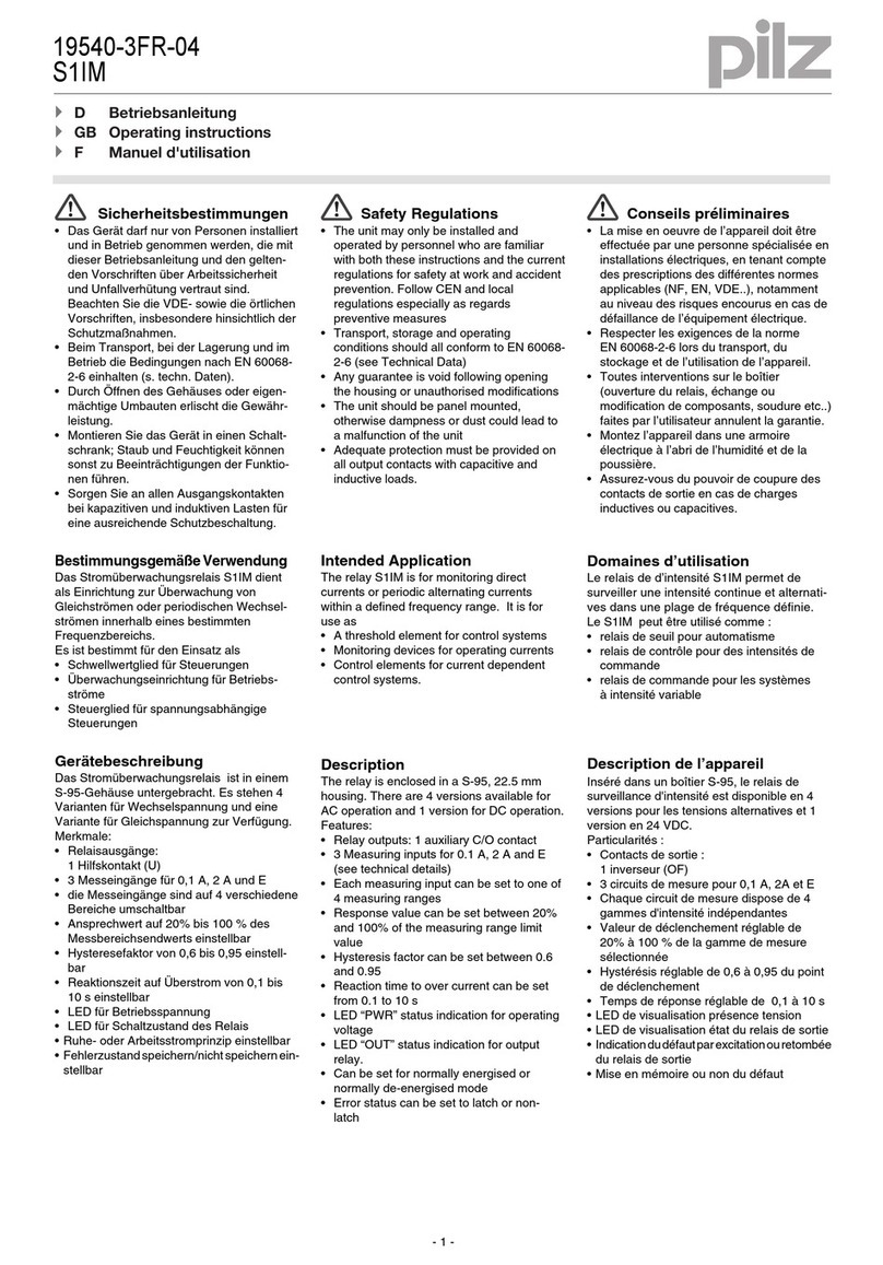
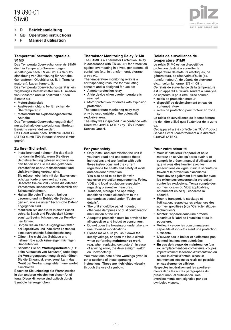
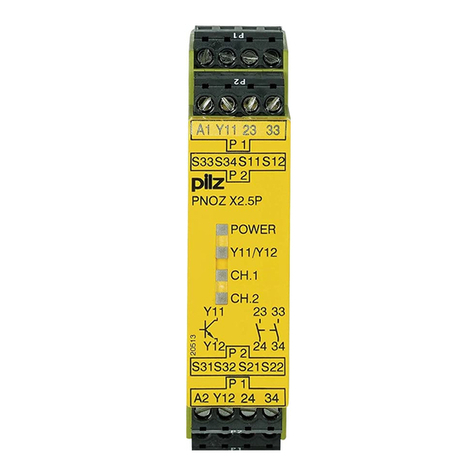
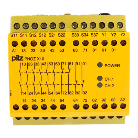
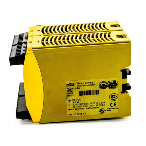
Pilz S1IM/UP User manual

- 1 -
Sicherheitsbestimmungen
• Das Gerät darf nur von Personen installiert
und in Betrieb genommen werden, die mit
dieser Betriebsanleitung und den gelten-
den Vorschriften über Arbeitssicherheit
und Unfallverhütung vertraut sind.
Beachten Sie die VDE- sowie die örtlichen
Vorschriften, insbesondere hinsichtlich der
Schutzmaßnahmen.
• Beim Transport, bei der Lagerung und im
Betrieb die Bedingungen nach EN 60068-
2-6 einhalten (s. techn. Daten).
• Durch Öffnen des Gehäuses oder eigen-
mächtige Umbauten erlischt die Gewähr-
leistung.
• Montieren Sie das Gerät in einen Schalt-
schrank; Staub und Feuchtigkeit können
sonst zu Beeinträchtigungen der Funktio-
nen führen.
• Sorgen Sie an allen Ausgangskontakten
bei kapazitiven und induktiven Lasten für
eine ausreichende Schutzbeschaltung.
Be
stimmungsgemäße Verwendung
Das Stromüberwachungsrelais S1IM/UP
dient als Einrichtung zur Überwachung von
Gleichströmen oder periodischen Wechsel-
strömen innerhalb eines bestimmten
Frequenzbereichs.
Es ist bestimmt für den Einsatz als
• Schwellwertüberwachung für Steuerungen
• Überwachungseinrichtung für Betriebs-
ströme
• Steuergerät für spannungsabhängige
Steuerungen
Gerätebeschreibung
Das Stromüberwachungsrelais ist in einem
S-95-Gehäuse untergebracht. Es stehen 4
Varianten für Wechselspannung und eine
Variante für Gleichspannung zur Verfügung.
Merkmale:
• Relaisausgänge:
1 Hilfskontakt (U)
• 3 Messeingänge für 0,1 A, 2 A und E
• die Messeingänge sind auf 4 verschiede-
ne Bereiche umschaltbar
• Ansprechwert auf 20 % bis 100 % des
Messbereichsendwerts einstellbar
• Hysteresefaktor von 0,6 bis 0,95 einstell-
bar
• Reaktionszeit auf Überstrom von 0,1 bis
10 s einstellbar
• LED für Versorgungsspannung
• LED für Schaltzustand des Relais
• Ruhe- oder Arbeitsstromprinzip einstellbar
• Fehlerzustand speichern/nicht speichern
einstellbar
• Polung der Messeingänge beliebig
• Messeingänge sind von der Versorgungs-
spannung galvanisch getrennt
Safety Regulations
• The unit may only be installed and
operated by personnel who are familiar
with both these instructions and the current
regulations for safety at work and accident
prevention. Follow CEN and local
regulations especially as regards
preventive measures
• Transport, storage and operating
conditions should all conform to
EN 60068-2-6 (see Technical Data)
• Any guarantee is void following opening
the housing or unauthorised modifications
• The unit should be panel mounted,
otherwise dampness or dust could lead to
a malfunction of the unit
• Adequate protection must be provided on
all output contacts with capacitive and
inductive loads.
Intended Application
The relay S1IM/UP is for monitoring direct
currents or periodic alternating currents
within a defined frequency range. It is for use
as
• A threshold element for control systems
• Monitoring devices for operating currents
• Control elements for current dependent
control systems.
Description
The relay is enclosed in a S-95, 22.5 mm
housing. There are 4 versions available for
AC operation and 1 version for DC operation.
Features:
• Relay outputs: 1 auxiliary C/O contact
• 3 Measuring inputs for 0.1 A, 2 A and E
(see technical details)
• Each measuring input can be set to one of
4 measuring ranges
• Response value can be set between 20 %
and 100 % of the measuring range limit
value
• Hysteresis factor can be set between 0.6
and 0.95
• Reaction time to over current can be set
from 0.1 to 10 s
• LED “PWR” status indication for operating
voltage
• LED “OUT” status indication for output
relay.
• Can be set for normally energised or
normally de-energised mode
• Error status can be set to latch or non-
latch
•
Polarity of the measuring inputs is irrelevant
• Measuring inputs are galvanically isolated
from the supply voltage
Conseils préliminaires
• La mise en oeuvre de l’appareil doit être
effectuée par une personne spécialisée en
installations électriques, en tenant compte
des prescriptions des différentes normes
applicables (NF, EN, VDE..), notamment
au niveau des risques encourus en cas de
défaillance de l’équipement électrique.
• Respecter les exigences de la norme
EN 60068-2-6 lors du transport, du
stockage et de l’utilisation de l’appareil.
• Toutes interventions sur le boîtier
(ouverture du relais, échange ou
modification de composants, soudure etc..)
faites par l’utilisateur annulent la garantie.
• Montez l’appareil dans une armoire
électrique à l’abri de l’humidité et de la
poussière.
• Assurez-vous du pouvoir de coupure des
contacts de sortie en cas de charges
inductives ou capacitives.
Domaines d’utilisation
Le relais de d’intensité S1IM/UP permet de
surveiller une intensité continue et alternati-
ves dans une plage de fréquence définie.
Le S1IM/UP peut être utilisé comme :
• relais de seuil pour automatisme
• relais de contrôle pour des intensités de
commande
• relais de commande pour les systèmes
à intensité variable
Description de l’appareil
Inséré dans un boîtier S-95, le relais de
surveillance d'intensité est disponible en 4
versions pour les tensions alternatives et 1
version en 24 VDC.
Particularités :
• Contacts de sortie :
1 inverseur (OF)
• 3 circuits de mesure pour 0,1 A, 2A et E
• Chaque circuit de mesure dispose de 4
gammes d'intensité indépendantes
• Valeur de déclenchement réglable de
20 % à 100 % de la gamme de mesure
sélectionnée
• Hystérésis réglable de 0,6 à 0,95 du point
de déclenchement
• Temps de réponse réglable de 0,1 à 10 s
• LED de visualisation présence tension
• LED de visualisation état du relais de
sortie
• Indication du défaut par excitation ou
retombée du relais de sortie
• Mise en mémoire ou non du défaut
• Polarité de l’entrée mesure indifférente
• Les entrées de mesure sont isolées
galvaniquement de la tension
d’alimentation
19 479-01
S1IM/UP
4D Betriebsanleitung
4GB Operating instructions
4F Manuel d'utilisation

- 2 -
Funktionsbeschreibung
Das Stromüberwachungsrelais arbeitet als
Schwellwertschalter. Der Ansprechwert für
Überschreiten des Messstroms Ian und die
Hysterese Iab sind einstellbar.
Voraussetzung: Die Versorgungsspannung
ist angelegt und das Arbeitsstromprinzip
(Beispiel) ist eingestellt. Die LED "PWR"
leuchtet. Die Funktion "nicht speichern"
wurde gewählt.
Überschreitet IMden eingestellten Ansprech-
wert Ian, zieht das Relais nach Ablauf der
Reaktionszeit an. Der Hilfskontakt 11-14 ist
geschlossen und 11-12 geöffnet. Die LED
"OUT" leuchtet.
Unterschreitet der Messstrom den durch die
Hysterese festgelegten Wert Iab, fällt das
Relais ab. Der Hilfskontakt 11-14 ist geöffnet
und 11-12 geschlossen. Die LED "OUT"
erlischt.
Ist statt des Arbeitsstromprinzips das Ruhe-
stromprinzip eingestellt, fällt das Relais bei
Überschreiten des Ansprechwerts Ian ab und
es zieht bei Unterschreiten des Abschalt-
werts Iab an.
Funktion "speichern/nicht speichern"
"Nicht speichern": Y2-Y3 offen
Nach Überschreiten des Ansprechwerts Ian
wechselt das Relais seinen Zustand.
Unterschreitet der Strom den Wert Iab,
wechselt das Relais automatisch wieder in
seinen Ausgangszustand.
"Speichern": Öffnerkontakt einesTasters
oder Brücke zwischen Y2 und Y3
Voraussetzung: Der Taster ist geschlossen.
Nach Überschreiten des Ansprechwerts Ian
wechselt das Relais seinen Zustand. Das
Relais behält seinen Zustand auch dann,
wenn der Strom Iab wieder unterschritten
wurde. Es wechselt erst nach Öffnen des
Tasters zwischen Y2 und Y3 oder nach Aus-
und Einschalten der Versorgungsspannung.
Hysterese
Der Ansprechwert Ian wird durch den Mess-
strom und den Faktor "%I" festgelegt. Es
stehen 3 Messeingänge 0,1 A, 2 AV und E
zur Verfügung. Diese Messbereichsendwerte
können durch 2 Schiebeschalter verkleinert
werden. Ian ergibt sich aus dem eingestellten
Messbereichsendwert und dem am Potentio-
meter "%I" eingestellten Faktor.
Iab wird durch das Potentiometer "HYST."
festgelegt. Der am Potentiometer eingestellte
Faktor multipliziert mit dem Wert Ian ergibt
den Abschaltwert Iab.
G1
K1
12 14
11
~
=
A2
(-)
A1
(+)
B
U
Y1 Y2 Y3
2 A E0,1 A
Arbeits-/Ruhestrom
De-energised/
energised mode
Mode excitation/
retombée
Speichern/
latching/
memorisé
Fig.1: Schematisches Schaltbild/ Wiring diagram/Schéma interne
Function Description
The current monitoring relay operates as a
threshold value element (threshold value
switch). The response value for exceeding
the measuring current Ian and the hysteresis
Iab can be set.
Requirement: Operating voltage is applied
and relay set to normally de-energised mode,
for example. The LED “PWR” is illuminated.
The function “Non-latching” was selected.
If IMexceeds the set response value Ian, the
relay energises after the reaction time has
elapsed. The auxiliary contact 11-14 is
closed and 11-12 is open. The LED “OUT” is
illuminated.
If the measuring current falls below the set
value determined via hysteresis Iab, then the
relay de-energises. The auxiliary contact 11-
14 is open and 11-12 is closed. The LED
“OUT” goes out.
If the relay is set to normally energisd mode,
the relay de-energises when Iab is exceeded
and energises if it falls below the trip value
Iab.
Latching / Non-Latching Function
“Non-latching”: Y2-Y3 open
After the response value Ian has been
exceeded the relay changes its status. If the
current falls below Iab the relay automatically
changes its status again.
“Latching”: N/C contact of a button or link
between Y2 and Y3.
Conditions for operation: Button is closed.
After Uan has been exceeded the relay
changes its status. The relay will keep that
status even if the current falls below Iab. It
will only change once the N/C contact on the
button between Y2 and Y3 has been opened
or after the operating voltage has been
switched off and back on.
Hysteresis
The response value Ian will be determined via
the measuring current and the factor “%I”.
There are 3 measuring inputs available 0.1A,
2 A and E (see technical details). The
measuring range limit values can be reduced
using the 2 sliding switches. Ian is given from
the set measuring range limit value and the
“%I” factor set on the potentiometer. Iab is set
on the potentiometer “HYST”. If the factor
set on the potentiometer is multiplied by Ian, it
gives the trip value Iab.
Description du fonctionnement
Le relais de surveillance d'intensité S1IM est
un relais à seuil. Le point de déclenchement
Ian et l'hystérésis Iab sont réglables.
Préalables: la tension d'alimentation est
présente et le mode de fonctionnement par
excitation du relais de sortie est sélectionné
(exemple). La LED "PWR" est allumée. La
fonction "non mémorisée" est sélectionnée.
Si l'intensité mesurée IMdépasse le point de
déclenchement Ian, le relais de sortie passe
en position travail au bout du temps de
réponse. Le contact 11-14 se ferme et 11-12
s'ouvre. La LED "OUT" est allumée.
Si l'intensité mesurée passe en dessous du
seuil réglé par l'hystérésis Iab, le relais de
sortie retombe. Le contact 11-14 s'ouvre et
11-12 se ferme. La LED "OUT" est éteinte.
Si le mode de fonctionnement par retombée
du relais de sortie est sélectionné, le relais
retombe en cas de dépassement du seuil
réglé Ian et remonte si l'intensité repasse en
dessous de Iab .
Fonction mise en mémoire
"Pas de mise en mémoire" : Y2-Y3 ouvert
En cas de dépassement du point de
déclenchement Ian , le relais change d'état. Si
l'intensité mesurée repasse en dessous du
seuil Iab , le relais repasse automati-
quement dans son état initial.
"Mise en mémoire ": pont entre Y2-Y3 ou
câblage d'un contact à ouverture d'un BP.
Préalable : le circuit est fermé. En cas de
dépassement du point de déclenchement Ian
, le relais change d'état. Le relais con- serve
cet état même si l'intensité mesurée repasse
en dessous du seuil Iab . Le relais repasse
en position initiale qu'après ouverture du
circuit Y2-Y3 ou coupure de la tension
d'alimentation.
Hystérésis
Le point de déclenchement Ian est réglé en
fonction de la gamme de mesure utilisée et
du facteur "%I". Trois circuits de mesure sont
disponibles: 0,1 A, 2 AV et E . Ces circuits de
mesure disponsent chacun de 4 gammes qui
sont sélectionnées à l'aide de 2
commutateurs. Ian est réglée en fonction de
la gamme de mesure utilisée et du poten-
tiomètre "%I".
Iab est réglée à l'aide du potentiomètre
"HYST.". La valeur de retombée Iab est le
produit de la valeur affichée Ian par le facteur
d'hystérésis sélectionné.
- 3 -
Fig. 2: Funktionsdiagramm/
Pulse diagram/
Diagramme fonctionnel
I
M
I
ab
I
an
12
12
LED
Y2 Y3
Y2 Y3
Y1 Y2
Y1 Y2
11
11
Arbeitsstromprinzip/
de-energised mode/
mode excitation
R hestromprinzip/
energised mode/
mode retombée
nicht speichernd/non-latching/non mémorisé speichernd/latching/mémorisé
Arbeitsstromprinzip/
de-energised mode/
mode excitation
14
14
11
11
t
R
IIbIb
t
R
Ia IIa
t
R
t
R
t
R
III
Hysterese (Iab): 0,8 x Ian
einstellbare Hysterese
tR: Reaktionszeit
Ia: IM> Ian: nach Ablauf von tRzieht das
Relais an und die LED "OUT" leuchtet.
IM< Iab: Relais fällt ab und LED
erlischt
Ib: IM> Ian: wie oben, aber Relais fällt ab
und LED "Out" erlischt
IM< Iab: Relais zieht an und LED
leuchtet
IIa: IM> Ian vor Ablauf von tR: Relais bleibt
abgefallen
IIb: wie oben, aber Relais bleibt angezogen
III: IM> Ian: s. oben
IM< Iab: Relais fällt erst ab, wenn
Y2-Y3 geöffnet ist.
Montage
Das Gerät muss in einen Schaltschrank mit
einer Schutzart von mind. IP54 eingebaut
werden. Zur Befestigung auf einer Norm-
schiene hat das Gerät ein Rastelement auf
der Rückseite.
Inbetriebnahme
Beachten Sie bei der Inbetriebnahme:
• Der Ausgangskontakt 11-12-14 ist ein
Hilfskontakt (z. B. für Anzeige oder
Schützansteuerung).
•Vor den Ausgangskontakt eine Siche-
rung (6 A flink oder 4 A träge) schalten,
um das Verschweißen des Kontaktes zu
verhindern.
• Leitungsmaterial aus Kupferdraht mit einer
Temperaturbeständigkeit von 60/75 °C
verwenden.
• Das Anzugsdrehmoment der Schrauben
auf den Anschlussklemmen darf max.
0,6 Nm betragen.
• Angaben im Kapitel "Technische Daten"
unbedingt einhalten.
Installation
The unit must be panel mounted (min. IP54).
There is a notch on the rear of the unit for
DIN-Rail attachment.
Hysteresis (Iab): 0,8 x Ian
hysteresis can be set
tR: Reaction time
Ia: IM> Ian: after tRhas elapsed the relay
energises and the LED “OUT” is
illuminated.
IM< Iab: relay de-energises and LED
goes out
Ib: IM> Ian: as above, but relay de-
energises and the LED “Out” goes out
IM < Iab: relay energises and the LED
is illuminated
IIa: IM> Iab before tRhas elapsed: relay
remains de-energised
IIb: as above, but the relay remains energised
III: IM> Ian: see above
I
M< Iab: relay de-energises once Y2-Y3
is open
Operation
Please note with operation:
• The output contact 11-12-14 is an auxiliary
contact (e.g. for signalling or contactor
control)
•To prevent contact welding, a fuse
(6 A quick or 4 A slow) must be
connected before the output contacts.
• Use copper wires that can withstand
temperatures of 60/75 °C.
• Tighten terminals to a max. 0.6 Nm
• Important details in the section “Technical
Data” should be noted and adhered to
• If there are HF sources near, we
recommend screened cables for the
measuring lines and the reset lines. Earth
Le relais doit être installé dans une armoire
ayant un indice de protection IP54. Sa face
arrière permet un montage sur rail DIN.
Mise en oeuvre
Remarques préliminaires :
• Le contact de sortie 11-12-14 et un contact
d'information (ex. pour signalisation ou
pilotage de relais).
• Protéger les contacts de sortie par des
fusibles (6 A rapides ou 4 A normaux)
pour éviter leur soudage.
• Le couple de serrage sur les bornes de
raccordement doit être d'au max. 0,6 Nm.
• Utiliser des câbles en cuivre supportant
des températures de 60/75°C
• Respecter les données indiquées dans le
chapitre „Caractéristiques techniques“.
• Nous vous conseillons l’utilisation de
câbles blindés pour le circuit de mesure et
de réarmement si une source HF est
Montage
Hystérésis (Uab): 0,8 x Ian
hystérésis réglable
tR: temps de réponse
Ia: IM> Ian: au bout du temps tR, le relais
monte et la LED "OUT" est allumée.
IM< Iab: le relais retombe et la LED
s'éteint.
Ib: IM> Ian: idem, mais le relais retombe et
la LED "Out" est éteinte.
IM< Iab: le relais monte et la LED
est allumée.
IIa: IM> Ian avant fin de tR: le relais reste
au repos
IIb: idem, mais le relais reste excité
III: IM> Ian: voir ci-dessus
IM< Iab: le relais retombe uniquement
si Y2-Y3 est ouvert.

- 4 -
Anschluss:
• Versorgungsspannung an die Klemmen
A1(+) und A2 (-) anschließen.
• Messeingang an 0,1 A oder 2 A oder E
anschließen
• Messbereichsendwert durch Schiebe-
schalter festlegen:
Beispiel: Messeingang 2 A, Messbereich
0,4 A: Schiebeschalter S1 auf Position 1
und S2 auf Position 0,2 bringen
WICHTIG!
• Messeingang E: Messbereich 25 A nur
für max. 10 s und Messbereich 50 A nur
für max. 2 s zulässig.
• Ansprechwert Ian festlegen: mit kleinem
Schraubendreher Potentiometer %I auf
gewünschten Wert stellen.
• Hysterese Iab festlegen: mit kleinem
Schraubendreher Potentiometer HYST.
auf gewünschten Wert stellen.
• Ruhe-/Arbeitsstromprinzip wählen:
- Ruhestromprinzip : Y1-Y2 offen
- Arbeitsstromprinzip:Y1-Y2 brücken
• Speichern/nicht speichern wählen:
- nicht speichernd: Y2-Y3 offen
- speichernd: Taster oder Brücke (Netz-
Reset) zwischen Y2-Y3 anschließen
Das Gerät ist betriebsbereit, sobald die
Versorgungsspannung eingeschaltet ist.
Wenn ein Taster zwischen Y2 und Y3
angeschlossen ist, muss dieser geschlossen
sein.
Anwendung
Das Gerät nur wie in den folgenden
Anschlussbildern anschließen!
Utilisation
Le relais doit être câblé uniquement
comme indiqué dans le schéma ci-
dessous.
the screen at either end and connect it to
terminal A2.
Connection:
• Connect operating voltage to terminals A1
(+) and A2 (-)
• Connect measuring input 0.1 A, 2 A or E
• Set the measuring range limit value using
the sliding switches.
Example: Measuring input 2 A, measuring
range 0.4 A: set sliding switch S1to
position 1 and S2 to position 0.2
IMPORTANT!
• Measuing input E: Measuring range 25
A can be set for a max. of 10 s and
measuring range 50 A for a max. of 2 s.
• To set response value Ian: using a small
screwdriver set the potentiometer %I to the
required value
• To set hystsresis Iab: using a small
screwdriver set the potentiometer “HYST”
to the required value
• Normally energised / de-energised mode
- Normally energised mode: Y1-Y2 open
- Normally de-energised mode: link Y1-Y2
• Selecting latching/non-latching
- non-latchng: Y2-Y3 open
- latching: connect a button or link (reset)
between Y2-Y3.
The unit is ready for operation as soon as the
operating voltage is applied. If a button
between Y2 and Y3 is connected, this must
be closed.
Application
Connect the unit according to the
following diagram.
Messeingang/Measuring input/entrées mesure 0,1 A 2 A E
Messbereich/Measuring Range/G. mesure 0,01 0,02 0,05 0,1 0,2 0,4 1 2 5 10 25 50
in/en A max. 10 s max. 2 s
Position Schiebeschalter/Sliding switch/
Position commutateur
S1 0,5 1 0,5 1 0,5 1 0,5 1 0,5 1 0,5 1
S2 0,2 0,2 1 1 0,2 0,2 1 1 0,2 0,2 1 1
installée près de l’appareil. Mettre le
blindage à la terre des 2 côtés et le relier à
la borne A2.
Branchement :
• Ramener la tension d'alimentation sur les
bornes A1(+) et A2 (-).
• Raccorder le circuit mesure 0,1 A ou 2 A
ou E
• Sélectionner la gamme de mesure à l'aide
des commutateurs :
Exemple : entrée mesure 2 A, gamme 0,4
A: mettre commutateur S1 sur position 1
et S2 sur position 0,2
REMARQUE !
• Circuit mesure E: gamme 25 A, utilisa-
tion max. 10 s et gamme 50 A, utilisa
tion max. 2 s
• Régler le point de déclenchement Ian à
l'aide du potentiomètre %I.
• Régler l'hystérésis Iab à l'aide du
potentiomètre HYST
• Sélectionner le mode de fonctionnement
du relais de sortie:
- par retombée : Y1-Y2 ouvert
- par excitation : ponter Y1-Y2
• Sélectionner la mémorisation ou non:
- pas de mémorisation : Y2-Y3 ouvert
- mémorisation : câbler un poussoir sur
Y2-Y3 ou ponter les 2 bornes (Power
reset).
L'appareil est prêt à fonctionner dès que la
tension d'alimentation est présente. Si un
poussoir est raccordé entre Y2 et Y3, ce
dernier ne doit pas être actionné.
Fig. 3: Anschlussbilder: Ruhestrom, nicht speichern (1)/Arbeitsstrom, nicht speichernd (2)/Arbeitsstrom, speichernd (3)/Ruhestrom, speichernd (4)
Connection Diagrams: Energised mode, non-latching (1) / De-energised mode, non-latching (2) / De-energised mode, latching (3) / Energised
mode, latching (4)
Schémas de branchement : par retombée du relais, non mémorisé (1)/Par excitation du relais, non mémorisé (2)/Par excitation, mémorisé(3)/
Par retombée du relais, mémorisé (4)
A2
A1 11
1L1
1L2
UB
12 14
0,1 A 2 A
Y1 Y2 Y3
IM
RL
E
11
A1
0,1 A
2 A
Y2
Y1
14
12 A2
Y3
IM
RL
1L1
1 L2
UB
E
11
A1
0,1 A
2 A
Y2
Y1
14
12 A2
Y3
IM
RL
1L1
1 L2
UB
E
11
A1
0,1 A
2 A
Y2
Y1
14
12 A2
Y3
IM
RL
1L1
1 L2
UB
E
(1) (2) (3) (4)
• Sind HF-Quellen in der Nähe, empfehlen
wir für die Mess- und die Reset-Leitung
abgeschirmte Leitungen zu verwenden.
Den Schirm beidseitig erden und mit
Klemme A2 verbinden.

- 5 -
Überprüfung - Fehlerursachen
Die Stromüberwachungsrelais reagieren
nicht auf den eingestellten Spannungswert,
falls
• der Messkreis unterbrochen oder kurzge-
schlossen ist
• Falschpolung von UBbei DC
• die Versorgungsspannung ausgefallen ist
• ein Defekt am Stromüberwachungsrelais
selbst vorliegt.
Abmessungen in mm ('')/Dimensions in mm ('')/Dimensions en mm ('')
122 (4.8")
75 (2.95")
87 (3.42")
22,5
(0,89")
Testing - Fault Causes
The current relay does not react to the set
voltage value if:
• The measuring circuit is interrupted or
short-circuited
• Incorrect polarity of UBwith DC
• Operating voltage UBfails/drops out
• The relay is defective
Test - Sources d'erreur
Le relais ne réagit pas aux seuils réglés en
cas de :
• coupure ou mise en court-circuit du circuit
de mesure.
• inversion de polarité (alimentation DC)
• non présence de la tension d'alimentation
• défaut interne du relais d'intensité
Technische Daten
Elektrische Daten
Versorgungsspannung UB
(einstellbar)
Spannungstoleranz UB
Frequenzbereich AC
Restwelligkeit UB (DC)
Leistungsaufnahme bei UB
Max. zulässiger Einschaltstrom
Ausgangskontakte
Hilfskontakt (U)
Gebrauchskategorie nach
EN 60947-4-1
EN 60947-5-1
Kontaktmaterial
Kontaktabsicherung extern nach
EN 60947-5-1
Schmelzsicherung flink
Schmelzsicherung träge
Elektrische Lebensdauer
(Nennlast)
Max. Schalthäufigkeit (Nennlast)
Messkreis
Frequenzbereich IM
Einstellbare Messbereichs-
endwerte IM
Hysterese
Ansprechwert Ian
AC: 24 V, 42 ... 48 V,
110 ... 127 V,230 ... 240 V
DC: 24 V
-15 % ... +10 %
50 ... 60 Hz
max. 160 %
AC: 2 VA
DC: 1 W
8 A AC
1
AC1: 240 V/0,1 ... 5 A/1200 VA
DC1: 24 V/0,1 ... 5 A/120 W
AC15: 230 V/2 A;
DC13: 24 V/1,5 A
AgCdO, Hartvergoldung 3 μfür
Niedriglastbereich 1 - 50 V/
1 - 100 mA/
AgCdO, 3 μgold plating for low
load range 1-50 V/1-100 mA/
AgCdO, avec revêtement or 3µ
pour commutation faibles
valeurs 1 - 50 V/1 - 100 mA
6 A
4 A
1 x 10⁵Schaltspiele/cycles/
manoeuvres
360/h
DC, 40 ... 400 Hz
0,1 A/0,05 A/0,02 A/0,01 A
2 A/ 1 A/0,4 A/ 0,2 A
5 A/10 A/25 A/50 A
0,6 ... 0,95 x Ian
Ian = IMx %I
Technical Details
Electrical data
Supply voltage UB
(can be set)
Voltage tolerance UB
Frequency range AC
Residual ripple UB (DC)
Power Consumption at UB
Max. permitted inrush current
Output contacts
Auxiliary contact (C/O)
Usage category acc. to
EN 60947-4-1
EN 60947-5-1
Contact material
External Contact Fuse Protection
EN 60947-5-1
Blow-out fuse quick acting
Blow-out fuse slow acting
Electrical Life (Normal load)
Max. Switching Frequency
(normal load)
Measuring circuit
Frequency Range IM
Selectable Measuring range limit
values IM
Hysteresis
Response Value Ian
Caractéristiques techniques
Caractéristiques électriques
Tension d’alimentation UB
(réglable)
Plage de la tension
d’alimentation UB
Fréquence AC
Ondulation résiduelle UB (DC)
Consommation pour UB
Pouvoir de coupure admissible max.
Contacts de sortie
Contacts d’information (OF)
Catégorie d'utilisation selon
EN 60947-4-1
EN 60947-5-1
Matériau des contacts
Protection des contacts
EN 60947-5-1
Fusible rapide
Fusible normal
Durée de vie électrique
Fréquence max de commutation
Circuits de mesure
Fréquence IM
Gamme de mesure IM
Hystérésis
Valeur d'enclenchement Ian

- 6 -
19 479-01, 2009-09 Printed in Germany
A
Pilz Ges.m.b.H.,
✆
01 7986263-0, Fax: 01 7986264
AUS
Pilz Australia,
✆
03 95446300, Fax: 03 95446311
B L
Pilz Belgium,
✆
09 3217570,
Fax: 09 3217571
BR
Pilz do Brasil,
✆
11 4337-1241, Fax: 11 4337-1242
CH
Pilz lndustrieelektronik GmbH,
✆
062 88979-30, Fax: 062 88979-40
DK
Pilz Skandinavien K/S,
✆
74436332, Fax: 74436342
E
Pilz lndustrieelektronik S.L.,
✆
938497433, Fax: 938497544
F
Pilz France Electronic,
✆
03 88104000, Fax: 03 88108000
FIN
Pilz Skandinavien K/S,
✆
09 27093700, Fax: 09 27093709
GB
Pilz Automation Technology,
✆
01536 460766,
Fax: 01536 460866
I
Pilz ltalia Srl,
✆
031 789511, Fax: 031 789555
IRL
Pilz Ireland Industrial Automation,
✆
021 4346535, Fax: 021 4804994
J
Pilz Japan Co., Ltd.,
✆
045 471-2281, Fax: 045 471-2283
MEX
Pilz de Mexico, S. de R.L. de C.V.,
✆
55 5572 1300, Fax: 55 5572 4194
NL
Pilz Nederland,
✆
0347 320477, Fax: 0347 320485
NZ
Pilz New Zealand,
✆
09- 6345-350, Fax: 09-6345-352
P
Pilz Industrieelektronik S.L.,
✆
229407594, Fax: 229407595
PRC
Pilz China Representative Office,
✆
021 62494658, Fax: 021 62491300
ROK
Pilz Korea,
✆
031 8159541,
Fax: 031 8159542
SE
Pilz Skandinavien K/S,
✆
0300 13990, Fax: 0300 30740
TR
Pilz Elektronik Güvenlik Ürünleri ve Hizmetleri Tic. Ltd. ¸Sti.,
✆
0224 2360180, Fax: 0224 2360184
USA
Pilz Automation Safety L.P.,
✆
734 354-0272, Fax: 734 354-3355
www
www.pilz.com
D
Pilz GmbH & Co. KG, Sichere Automation, Felix-Wankel-Straße 2, 73760 Ostfildern, Deutschland,
✆
+49 711 3409-0, Fax: +49 711 3409-133,
E-Mail: [email protected]
Impedanz der Messeingänge
Überlastbarkeit der Messeingänge
Max. Messstrom IM
AC-/DC-Korrektur
Polung der Messeingänge
Prüfspannung: Messeingänge -
Versorgungsspannung
Restwelligkeit IM (DC)
Reaktionszeit tR
Messzeit bei tRmin und 1,6facher
Übersteuerung (Strom)
Temperaturabhängigkeit
Spannungsabhängigkeit
Umweltdaten
EMV
Schwingungen nach
Frequenz
Amplitude
Klimabeanspruchung
Luft- und Kriechstrecken
Umgebungstemperatur
Lagertemperatur
Mechanische Daten
Mechanische Lebensdauer
Querschnitt des Außenleiters
(Schraubklemmen)
1 Leiter
flexibel
2 Leiter gleichen Querschnitts
flexibel mit Aderendhülse ohne
Kunststoffhülse
flexibel mit TWIN-Aderendhülse
Anzugsdrehmoment für
Schraubklemmen
Einbaulage
Gehäusematerial
Front
Gehäuse
Schutzart
Einbauraum (z. B. Schaltschrank)
Gehäuse
Klemmenbereich
Abmessungen (Schraubklemmen)
H x B x T
Gewicht
Impedance of Measuring Inputs
Overload Capacity
Max. Measuring Current IM
AC-/DC Correction
Polarity of the measuring inputs
Test voltage: measuring inputs -
supply voltage
Residual ripple IM(DC)
Reaction time tR
Measuring time at t Rmin and 1, 6 x
over control (current)
Temperature Variation
Voltage Variation
Environmental data
EMC
Vibration to
Frequency
Amplitude
Climatic suitability
Airgap creepage
Ambient temperature
Storage temperature
Mechanical data
Mechanical life
Cable cross section (screw
terminals)
1 core
flexible
2 core, same cross section
flexible with crimp connectors,
without insulating sleeve
flexible with TWIN crimp
connectors
Torque setting for screw terminals
Mounting position
Housing material
front panel
housing
Protection type
Mounting (e.g. control cabinet)
Housing
Terminals
Dimensions (screw terminals)
H x W x D
Weight
Impédance du circuit de mesure
Charge max.
Intensité de mesure max. IM
Corrections AC/DC
Polarité de l’entrée mesure
Tension d'essai: l’entrée mesure -
Tension d'alimentation
Ondulation résiduelle IM(DC)
Temps de réponse tR
Temps de mesure pour tRmin et
intensité mesurée égale à 1,6 x
intensité affichée
Variation avec la température
Variation avec la tension
Environnement
CEM
Vibrations selon
Fréquence
Amplitude
Sollicitations climatiques
Cheminement et claquage
Température d’utilisation
Température de stockage
Données mécaniques
Durée de vie mécanique
Capacité de raccordement (borniers
à vis)
1 conducteur
souple
2 câbles de même diamètre
souple avec embout sans
chapeau plastique
souple avec embout TWIN
Couple de serrage (borniers à vis)
Position de montage
Matériau du boîtier
face avant
boîtier
Indice de protection
Lieu d'implantation (par
ex. armoire)
Boîtier
Borniers
Dimensions (borniers à vis)
H x L x P
Poids
0,1 A: 2,5 Ω
2 A : 125 mΩ
E: 5 mΩ
0,1 A: max. 0,2 A
2 A: max. 2,5 A
E: max. 15 A,
max. 25 A für/for/pour max. 10 s,
max. 50 A für/for/pour max. 2 s
0,1 A/2 A/50 A
erfolgt bei Sinus automatisch/
automatic/automatique en cas
de sinus
beliebig/ irrelevant/indifférente
bei/at/pour UB= 24 V DC: 3 kV
bei/at/pour UB= ... V AC: 4 kV
160 %
0,1 ... 10 s
max. 200 ms
± 0,05% je/per/par +1°C
± 0,1% je/per/par ΔU
EN 60947-5-1, EN 61000-6-2
EN 60068-2-6
10 ... 55 Hz
0,35 mm
EN 60068-2-78
EN 60947-1
-15 ... +55 °C
-40 ... +85 °C
10 x 106 Schaltspiele/cycles/
manoeuvres
0,20 ... 4,0 mm
2
/24-10 AWG
0,20 ... 2,5 mm2/24-14 AWG
0,6 Nm
beliebig/any/au choix
ABS UL 94 V0
PPO UL 94 V0
IP54
IP40
IP20
87 x 22,5 x 121 mm
165 g
Table of contents
Other Pilz Relay manuals

Pilz
Pilz PZE X5 User manual

Pilz
Pilz PZE X4.1P User manual

Pilz
Pilz PZE X4VP User manual

Pilz
Pilz PSWZ X1P Owner's manual

Pilz
Pilz PNOZ X9P AC/DC User manual

Pilz
Pilz PNOZ X10.1 User manual

Pilz
Pilz PNOZ s7.1 User manual

Pilz
Pilz PNOZ X2.4V User manual

Pilz
Pilz PNOZ X3 Owner's manual

Pilz
Pilz PNOZ po4p User manual