Cannon MAGNUMTM 5 User manual

MAGNUMTM 5
MAGNUMTM 10
MAGNUMTM 10 TS
ELECTRIC DOWNRIGGERS
Installation Instructions

© 2020
|
Johnson Outdoors Marine Electronics, Inc.
|
cannondownriggers.com
2
INTRODUCTION
Made by Cannon
Johnson Outdoors
Marine Electronics, Inc.
121 Power Drive
Mankato, MN 56001 USA
Downriggers
Produced in 2020
MAGNUM ELECTRICAL DOWNRIGGER
MODEL 1902310
12V DC
30 A
SER NO U365 CN12345
EXAMPLE
THANK YOU
Thank you for purchasing a Cannon downrigger. We have designed your new downrigger to be an accurate and reliable tool that will
enhance fishing control and improve your ability to catch fish. We hope that you enjoy the use of your new downrigger and enjoy the
benefit of controlled depth fishing for years to come by always following safe boating practices and laws wherever you are fishing.
REGISTRATION
Remember to keep your receipt and immediately register your
downrigger. To receive all the benefits for your product warranty,
please fill out and mail the enclosed registration card, or you may
complete registration online at cannondownriggers.com.
PRODUCT INFORMATION (For Consumer Reference Only)
Model:________________________________________________________________________________________________________________
Serial Number: ________________________________________________________________________________________________________
Purchase Date: ________________________________________________________________________________________________________
Store Where Purchased:_________________________________________________________________________________________________
NOTICE: The serial number on your Cannon Magnum
downrigger is located on the bottom of the
downrigger frame.
SERIAL NUMBER
Your Cannon 11-character serial number is very important. It
helps to determine the specific model and year of manufacture.
When contacting Consumer Service or registering your product,
you will need to know your product’s serial number. We
recommend that you write the serial number down in the space
provided below so that you have it available for future reference.

© 2020
|
Johnson Outdoors Marine Electronics, Inc.
|
cannondownriggers.com 3
SAFETY CONSIDERATIONS
Please thoroughly read this user manual. Follow all instructions and heed all safety and cautionary notices below. Use of this
downrigger is only permitted for persons that have read and understood these user instructions. Minors may use this product only
under adult supervision.
WARNING
You are responsible for the safe and prudent operation of your vessel. We have designed your Cannon product to be an accurate
and reliable tool that will enhance boat operation and improve your ability to catch fish. This product does not relieve you from the
responsibility for safe operation of your boat. You must avoid hazards to navigation and always maintain a permanent watch so you
can respond to situations as they develop. You must always be prepared to regain manual control of your boat. Learn to operate
your Cannon product in an area free from hazards and obstacles.
WARNING
It is recommended to only use Johnson Outdoors approved accessories with your Cannon. Using non-approved accessories
including those used to mount or control your product may cause damage, unexpected operation and injury. Be sure to use the
product and all approved accessories, including remotes and/or devices, safely and in a manner directed to avoid accidental or
unexpected operation. Keep all factory installed parts in place including motor, electronic and accessory covers, enclosures and
guards. Failure to adhere to this warning may affect your warranty.
WARNING
Do not touch the Spool/Reel while the downrigger is in use. Holding or touching it may result in moderate to severe injuries.

© 2020
|
Johnson Outdoors Marine Electronics, Inc.
|
cannondownriggers.com
4
KNOW YOUR BOAT
Stern
Inboard
Outboard
Keel
Bow
Port
Port Starboard
Starboard
Gunwale Transom
Bow
Hull
Stern
Gunwale

© 2020
|
Johnson Outdoors Marine Electronics, Inc.
|
cannondownriggers.com 5
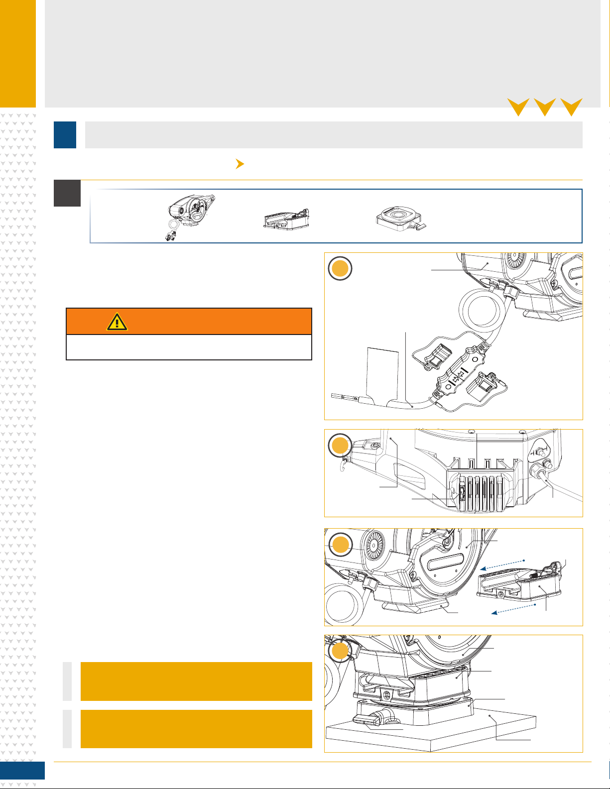
INSTALLATION
Stern
INSTALLING THE MAGNUM
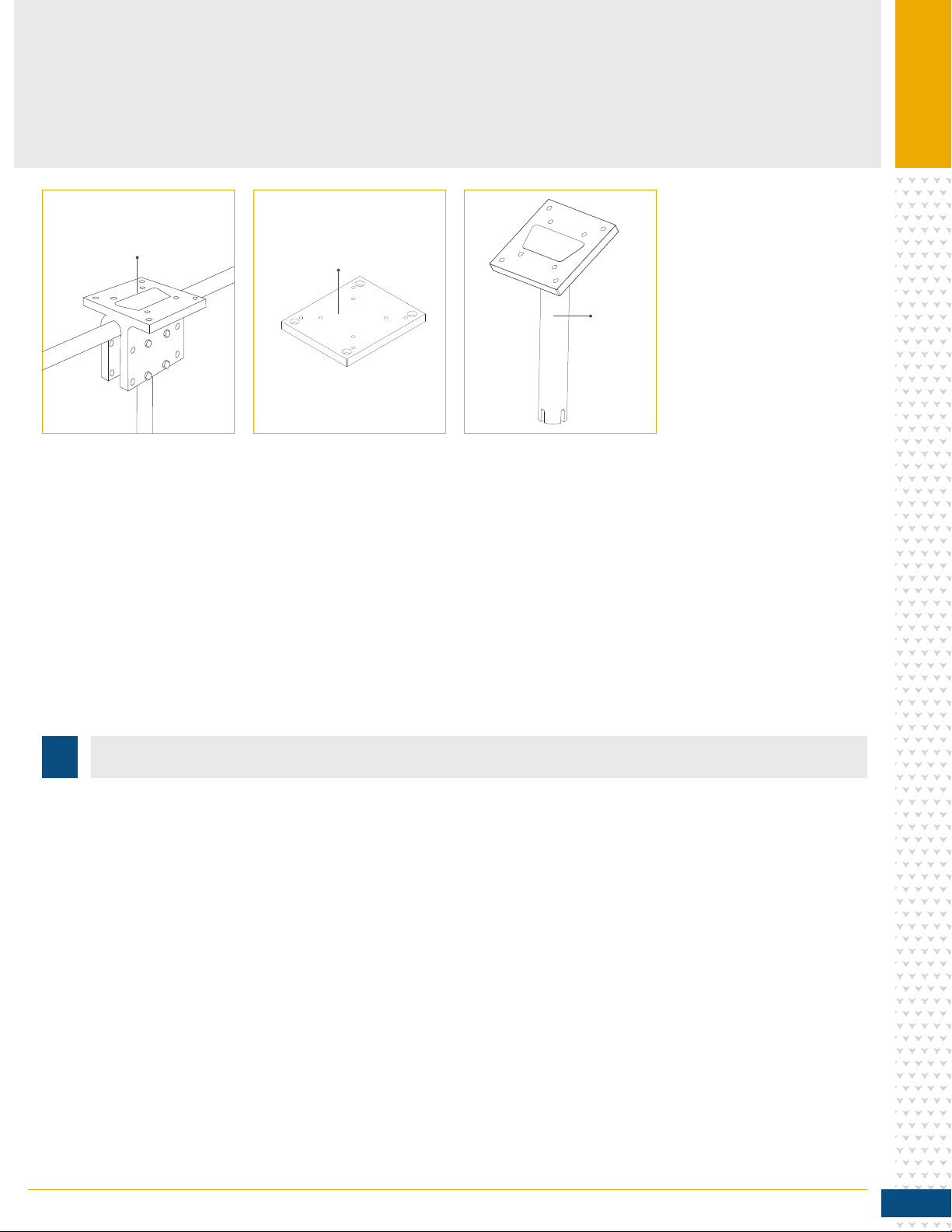
Your new Cannon Magnum comes with the hardware you’ll need to directly install it to the boat. Cannon recommends mounting your
downrigger using a deck plate and also offers a variety of accessories to customize your installation. Read these installation instructions
to learn more and visit cannondownriggers.com for a full list of accessories. To install the downrigger directly to the boat, please follow
the instructions provided in this manual. Please review the parts list, mounting considerations and tools needed for installation prior to
getting started. For additional product support, please visit cannondownriggers.com.
INSTALLATION PARTS LIST
30
32
34
36
18
38
G
H
12
10
24
22
F
22
20
20
26
U
V
D
E
A
B
C
14
2
8
4
28
6
16
pNot shown on Parts Diagram.
✖This part is included in an assembly and cannot be ordered individually.
tOnly available with the Magnum TS series downrigger.
Item /
Assembly Part # Description Qty.
A✖CANNON DOWNRIGGER ASSEMBLY 1
B3991913 CNN ASSY, SWIVEL BASE 1
C3991930 ASSY-CNN, MNT BASE 1
D3392010 tASSY, BOOM TELESCOPIC, SS *TS* 1
E2210821 ASY BOOM TELESCOPIC 1
F3991904 ASSY-CNN, ROD HOLDER 1
G3994807 ASSY-BAG, DT PRO/MAG ST 1
H3994815 BAG ASSY, BOOM END 1
U2277002A ASY HDW RELEASE UNIVERSAL 2
V 2200109 tSALTWATER RELEASE, OR8 BE *TS* 2
29280720 HDW SCR 1/4 20X2 TRUSS HD PHIL 4
42371712 WASHER-FLAT 9/32 X 5/8 X 1/16 4
62263103 NUT-1/4-20 NYLOCK SS 5
89280713 HDW SCR 1/4 20X1 1/2 TRUSS HEA 4
10 3390103 KNOB, SOFT GRIP, CLUTCH 1
12 2263102 NUT-HEX 1/4-20 SS 300SRS 1
14 9040040 HDW BOLT 1/4-20 ROLLEDTHD HOOK 1
16 3393461 SCREW-1/4-20 x 2" SS, PPH 1
18 3397900 BALL HOOK EXTRUSION 1
20 3390101 KNOB-CANNON, SOFT GRIP 2
22 2287002 HDW SPRING RELEASE PIN 2
24 3392033 TUBE, DUAL AXIS RD HLDR 1
26 3394200 ARM, DUAL AXIS-ROD HLDR 1
28 2372100 SCREW-#8-18 X 5/8 THD* (SS) 1
30 9100101 CUSHION SLEEVE TERMINATOR 1
32 9100100 CON TERMINATOR 1
34 2200148 ASY SNAP & INSULATOR 1
36 9100620 HDW SNAP SWIVEL 4/0-37 MARLIN 1
38 3990200 ASSY-CNN, BOOM END 1
40 3390910 HANDLE-CRANK, MANUAL 1
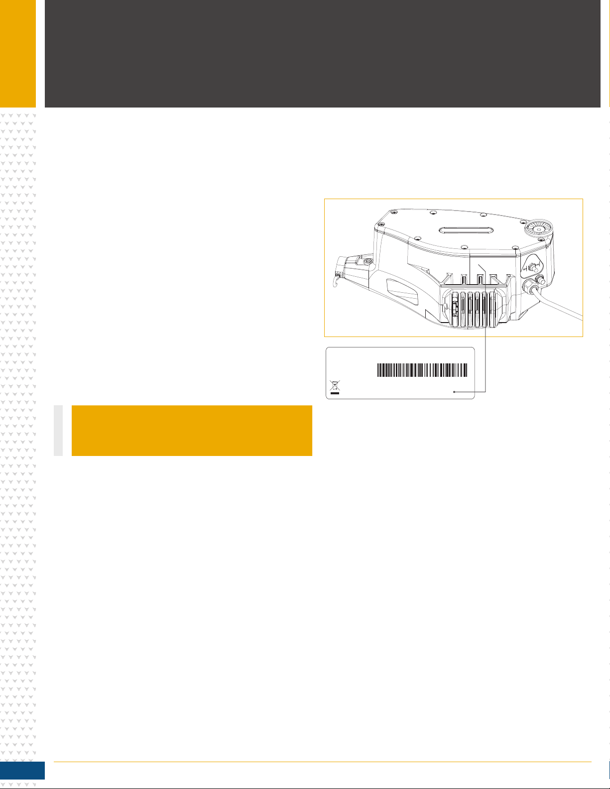
42 3397175 pINSTRCT, INSTALL, MAGNUM 1
44 3397139 pMANUAL DISCLAIMER DWNLOAD INFO 1
46 2290828 24" BOOM-HEAVY DUTY (MAG 5) 1
48 3395905 ADAPTER, BOOM END (MAG 5) 1
40
46
48

© 2020
|
Johnson Outdoors Marine Electronics, Inc.
|
cannondownriggers.com
6
INSTALLING THE MAGNUM
Before mounting a Cannon downrigger, please give consideration
to the following:
1. Clear mounting location - Choose a good location on your
boat to mount your downrigger. Downriggers are mounted
to the Gunwale of the boat. Make sure the area under the
mounting location is clear to drill holes and install nuts and
washers. Make sure that the mounting location is free from
cables or wiring and other critical boat structures. The
movable parts of the downrigger, such as the telescopic
boom should be positioned so that the weight is far enough
beyond the edge of the boat so that it and the downrigger
will not encounter any obstructions during operation. In
some cases, the profile of the Gunwale is raised which may
prevent the downrigger from sitting all the way against the face of the Gunwale. It may be necessary to shim or cut away around
these areas to securely complete the installation. Mounting accessories are recommended to accommodate difference in
mounting locations and mounting situations.
2. Operation of the downrigger - Consider the operation of the downrigger at the selected mounting location. A downrigger should be
mounted in a location where it is easy to observe your fishing rod and react quickly to operate the downrigger once there is a fish
on the line. There should be enough space to use the downrigger comfortably and with proper ergonomics. It should be easy to
reach while still maintaining control of the boat and to retrieve gear. The location of the telescopic boom, weight and rod holder
when fully installed should not encounter obstructions. The power cables should reach their intended power source from the
mounting location. When installing multiple downriggers, consider the spacing between downriggers units. Mount the downrigger
in a location where it is easy to route transducer cables and other downrigger accessory cables and wiring, either to a power
source or sonar unit. Make sure that the mounting location does not create a tripping hazard for power cables or accessories
used during operation.
3. Mounting accessories - Consider the use of a mounting
accessory when installing your downrigger. Consider the
location and angle of the rod placement when the downrigger
is fully installed on the mounting surface. A deck plate is
recommended to provide adequate support and to maximize
the capability of the product. Cannon offers a complete line of mounting accessories that allow you to optimize your installation
to fit the way you fish. Before making any permanent changes to your boat, consider what accessories might be used in your
application. To see the complete line of mounting accessories review the variety of accessories explained in this document or visit
cannondownriggers.com.
NOTICE: When using the telescopic boom, we strongly
recommend the use of a deck plate on all boats to provide
adequate stability for the downrigger.
MOUNTING CONSIDERATIONS
Typical Mounting Location
SternBow
Gunwale
(Top Edge)
NOTICE: This downrigger weighs approximately
19 lbs. We recommend having a second person
help with the installation.
NOTICE: Illustrations are for reference only and may differ
from your actual installation.

© 2020
|
Johnson Outdoors Marine Electronics, Inc.
|
cannondownriggers.com 7
INSTALLING THE MAGNUM
TOOLS AND RESOURCES REQUIRED
Deck Plate
Gimbal
Mount
Side/Rail
Mount
• 9/32” Drill Bit
• Pencil, Marker or similar Marking Tool
• Drill
• 7/16” Box End Wrench
• Wire Cutters
• Pliers
• #3 Phillips Screw Driver
• Needle Nose Pliers
• Masking tape
• Anti-seize
• A second person to help with
the installation
DECK PLATES
Cannon deck plates prevent
deflection and add stability
to decks. Recommended for
attaching the downrigger
for initial installation or for
mounting accessories. They are
necessary to add extra strength
to the base material of the
boat. Options include Deck
Plate (Item No. 2200693).
SIDE/RAIL MOUNTS
Can be mounted to a welded
T-section. Side/Rail Mounts
(Item No. 2250940) can also be
used at the two rail section butt
joint. In both installations it is
recommended to use a non-slip
material, such as rubber or a
thin wood sheet, between
metal surfaces.
GIMBAL MOUNTS
Designed to fit medium-sized
flush mounted rod holders
built into the gunwale of larger
fishing boats and cruisers.
Only sturdy, high quality rod
holders should be used for this
temporary mounting system.
Gimbal mounts are available
in 9” or 12” post lengths with
Standard (Item No. 2250927 and
2250928) and Stainless Steel
options (Item No. 1903005
and 1903006).

© 2020
|
Johnson Outdoors Marine Electronics, Inc.
|
cannondownriggers.com
8
INSTALLING THE BASE
INSTALLING THE BASE
a. Review the mounting considerations at the
beginning of the installation and select a mounting
location. Make sure the downrigger is not
connected to a power source.
b. Take the Mounting Base (Assembly #C) and
attach it to the Downrigger Assembly (Assembly
#A). The Mounting Base is keyed with the bottom
of the Downrigger Assembly. The Soft Grip Knob
on the Mounting Base screws into a metal plate on
the bottom of the Downrigger Assembly. Secure the
Mounting Base to the Downrigger Assembly so that
the Soft Grip Knob is in the correct position.
c. In the final Installation, the Mounting Base is
installed on the Swivel Base (Assembly #B) for
Magnum 10 downriggers. If desired, hold the
Downrigger Assembly (Assembly #A) with the Swivel
Base at the selected mounting location to check
fit and function. Use a second person to help with
the installation and test to make sure that the
downrigger will operate as desired.
d. Determine if a mounting accessory, such as a
recommended deck plate is needed. Refer to
the installation instructions included with any
mounting accessory and then complete the
downrigger installation.
INSTALLATION
Power CablePower Cable
DownriggerDownrigger
AssemblyAssembly
DownriggerDownrigger
AssemblyAssembly
DownriggerDownrigger
AssemblyAssembly
Mounting BaseMounting Base
Swivel BaseSwivel Base
MountingMounting
LocationLocation
Release KnobRelease Knob
SoftSoft
GripGrip
KnobKnob
DownriggerDownrigger
AssemblyAssembly
MetalMetal
PlatePlate
MetalMetal
PlatePlate
1a
1b
1b
1c
1
WARNING
Make sure the downrigger is not connected to a power source.
#A x 1 #C x 1 #B x 1
Item(s) needed:
NOTICE: The Release Knob on the Swivel Base can
face any direction for your final installation.
NOTICE: The Swivel Base can be purchased as an
accessory for the Magnum 5 at cannondownriggers.com.
PowerPower
CableCable

© 2020
|
Johnson Outdoors Marine Electronics, Inc.
|
cannondownriggers.com 9
INSTALLING THE BASE
e. Once satisfied with the selected location, begin
by using the Swivel Base or Mounting Base as a
mounting template.
f. Take the Base and place it at the desired location.
Make sure that the Release Knob or Soft Grip
Knob is orientated in the desired direction and the
mounting location is clear to drill holes and can
accommodate mounting hardware.
g. With the Base in place, use a pencil, marker, or
similar marking tool to mark the location of the 4
mounting holes on the mounting location.
2
3
Swivel BaseSwivel Base
SwivelSwivel
BaseBase
MountingMounting
LocationLocation
MountingMounting
LocationLocation
MountingMounting
LocationLocation
MountingMounting
LocationLocation
Swivel BaseSwivel Base
ReleaseRelease
KnobKnob
ReleaseRelease
KnobKnob
Mounting HolesMounting Holes
MountingMounting
HoleHole
MountingMounting
HoleHole
Mounting HoleMounting Hole
MountingMounting
HolesHoles
MountingMounting
HoleHole
Mounting HoleMounting Hole
2e 2f
2g
3h
3i
h. With the location marked, set the Base aside
and drill holes, one in each of the four marked
locations using a Drill with a 9/32" Drill Bit.
i. Return the Base to the mounting location and
align it with the four drilled holes. Orientate it
back in the desired direction so the mounting
holes in the Base align with the drilled holes in the
mounting location and the Release Knob or Soft
Grip Knob in the desired direction.
Mounting HolesMounting Holes
Release KnobRelease Knob
MarkedMarked
LocationLocation
MarkedMarked
LocationLocation
HolesHoles
Marked LocationMarked Location
HolesHoles
MarkedMarked
LocationLocation
MarkedMarked
LocationLocation
Holes in Marked LocationHoles in Marked Location
HolesHoles
NOTICE: When drilling holes, it is helpful to first cover
the surface with masking tape. This will help keep the
boat surface unmarked and help with cleanup. Cover
the surface and then mark the location to drill. Once
the pilot holes are drilled remove the masking tape
before continuing installation.
NOTICE: Mounting the Swivel Base is optional. If it
is preferred to use the Mounting Base only, use the
mounting base as a template for drilling holes. To
secure the Mounting Base to the deck use four 1/4-20
X 2" Phillips Truss Head Machine Screws (Item # 2)
four Flat Washers (Item #4) and four 1/4-20 Nylock
Nuts (Item # 6).
NOTICE: If only installing the Mounting Base and the
Swivel Base was either not used or not inculded with
your downrigger, continue to Step 6.

© 2020
|
Johnson Outdoors Marine Electronics, Inc.
|
cannondownriggers.com
10
INSTALLING THE BASE
j. Take four of the 1/4-20 X 2" Phillips Truss Head
Machine Screws (Item # 2) and apply anti-seize.
Then place one in each of the Mounting Holes. The
Truss Screws should pass through the Swivel Base
and the drilled holes in the mounting location.
k. Secure the Truss Screws in place with four Flat
Washers (Item #4) and four 1/4-20 Nylock Nuts
(Item # 6). Take one Flat Washer and place it on
the end of each Truss Screw. Secure each Truss
Screw and Flat Washer with Nylock Nuts using a
#3 Phillips Screwdriver. Hand tighten, or tighten to
45 ft-lbs. To prevent seizing of the stainless steel
hardware, do not use high speed installation tools.
#6 x 4
#4 x 4
#2 x 4
Item(s) needed:
4
5
MountingMounting
LocationLocation
Mounting LocationMounting Location
Nylock NutsNylock Nuts
FlatFlat
WasherWasher
FlatFlat
WasherWasher
FlatFlat
WasherWasher
FlatFlat
WasherWasher
Truss Head ScrewsTruss Head Screws
Mounting HolesMounting Holes
PhillipsPhillips
ScrewsScrews
PhillipsPhillips
ScrewsScrews
PhillipsPhillips
ScrewsScrews
PhillipsPhillips
ScrewsScrews
SwivelSwivel
BaseBase
Swivel BaseSwivel Base
4j
4j
5l 5m
NOTICE: To prevent seizing of the stainless steel
hardware, do not use high speed installation tools.
Wetting the screws or applying an anti-seize may help
prevent seizing.
l. The Mounting Base will be installed to the Swivel
Base. At the beginning of the installation, the
Mounting Base was attached to the Downrigger
Assembly. Recall the orientation of the Soft
Grip Knob and the orientation of the Downrigger
Assembly in its intended installation position.
m. Remove the Mounting Base from the Downrigger
Assembly and place it back on the Swivel Base
in the same orientation. The mounting holes in
the corners of both the Swivel Base and Mounting
Base should align. Take four of the 1/4-20 X 1 1/2"
Truss Head Screws (Item # 8) and use them to
secure the Mounting Base to the Swivel Base using
a Phillips screwdriver.
#8 x 4
Item(s) needed:
SwivelSwivel
BaseBase
Swivel BaseSwivel Base
MountingMounting
BaseBase
MountingMounting
BaseBase
MountingMounting
LocationLocation
NOTICE: Consider installing an optional Cannon Lock on
the Mounting Base for added security. (Item No. 1903020)

© 2020
|
Johnson Outdoors Marine Electronics, Inc.
|
cannondownriggers.com 11
INSTALLING THE CLUTCH KNOB
6
1
n. Once the Base(s) are secured together, replace
the Downrigger Assembly on the Mounting
Base and secure it with the Soft Grip Knob.
Hand tighten.
Item(s) needed:
Downrigger AssemblyDownrigger Assembly
DownriggerDownrigger
AssemblyAssembly
Mounting BaseMounting Base
SoftSoft
GripGrip
KnobKnob
SpoolSpool
SpoolSpool
ClutchClutch
KnobKnob
Swivel BaseSwivel Base
Mounting LocationMounting Location
6n
1a
a. Take the Clutch Knob (Item #10) and install it into
the side of the Downrigger Assembly. The Clutch
Knob is installed on the side of the downrigger
where the Spool is located. When installing the
Clutch Knob, insert it into the center of the
downrigger spool and turn it counterclockwise
to tighten.
#10 x 1

© 2020
|
Johnson Outdoors Marine Electronics, Inc.
|
cannondownriggers.com
12
INSTALLING THE BOOM OR TELESCOPIC BOOM
1Item(s) needed:
Mounting HoleMounting Hole
Mounting HoleMounting Hole Not a throughNot a through
Mounting HoleMounting Hole
Telescopic BoomTelescopic Boom
Center TubeCenter Tube MiddleMiddle
TubeTube OuterOuter
TubeTube
Telescopic BoomTelescopic Boom
BoomBoom BoomBoom
AdapterAdapter
Boom ClampsBoom Clamps
CableCable
TieTie
Narrow EndNarrow End
Toward DownriggerToward Downrigger
Narrow EndNarrow End
Wide EndWide End
Toward Boom EndToward Boom End
Wide EndWide End
Wide EndWide End
Telescopic BoomTelescopic Boom
Boom ClampBoom Clamp Boom ClampBoom Clamp
1b
1a
1b
1c
a. For the Magnum 5 downrigger, take the Boom
(Item #46) and identify both ends. The end of
the Boom with the screw hole closest to the edge
will be placed the furthest from the Downrigger
Assembly. Take the Boom Adapter (Item #48) and
insert it into the far end of the Boom. This will be
secured later.
b. For the Magnum 10 or Magnum 10 TS downrigger,
take the Telescopic Boom (Assembly #D or
Assembly #E) and cut the Cable Tie holding the
three tubes of the boom together with a wire
cutter or cutting tool. Remove the cut Cable
Tie and loosen the Boom Clamps by turning
them counterclockwise at the narrow end of the
Telescopic Boom.
c. The Outer Tube that makes up the wider end of the
Telescopic Boom has 3 holes used for mounting
it to the Downrigger Assembly. The tubes in the
Telescopic Boom need to be extended so that the
holes used to mount the boom to the downrigger are
unobstructed and are free to pass a bolt through.
d. With the Clamps on the Telescopic Boom loosened,
the tubes of the boom can slide apart. Slide the
Center Tube about 2 inches out from the original
position and then re-tighten the Boom Clamp
towards the narrower end of the boom turning
clockwise. Slide the Middle Tube about 2 inches
out from its original position and tighten the second
clamp. Check the opposite end of the boom to see
if all three holes on the Outer Tube are clear to
pass mounting hardware. If not, re-adjust the Boom
Clamps and tubes to expose the mounting holes.
Secure the clamps by turning them clockwise so
that the tubes do not slide, then set aside.
#D x 1 or #E x 1 #46 x 1 #48 x 1

© 2020
|
Johnson Outdoors Marine Electronics, Inc.
|
cannondownriggers.com 13
INSTALLING THE BOOM OR TELESCOPIC BOOM
2
#12 x 1 #14 x 1
Item(s) needed:
Ball HookBall Hook Ball HookBall Hook
StainlessStainless
Steel Hex NutSteel Hex Nut
StainlessStainless
Steel Hex NutSteel Hex Nut
2d 2d
e. Take the Ball Hook (Item #14) and place the
Stainless Steel Hex Nut (Item #12) on it. Turn the
Hex Nut far onto the Ball Hook, nearly to the end
of the threads. Set the Ball Hook Assembly aside.
e. Take the Ball Hook Extrusion (Item #18) and place
it over the wider end of the Telescopic Boom,
opposite the Clamps or the downrigger side of the
Boom. At this point in the installation, the Ball
Hook Extrusion will slide freely on the Boom.
f. Take the Boom with the Ball Hook Extrusion and
note the location of the three holes on the end of
the boom. The two holes across from each other will
be used to secure it to the Downrigger Assembly.
The two holes are aligned so that hardware can
pass straight through to secure it to the Downrigger
Assembly. Place it into the end of the Downrigger
Assembly and rotate the holes so that the mounting
holes in the Boom Assembly are aligned with the
mounting holes in the Downrigger Assembly.
3
#18 x 1
Item(s) needed:
Ball HookBall Hook
ExtrusionExtrusion
Ball HookBall Hook
ExtrusionExtrusion
BoomBoom
BoomBoom
3e
3e
Narrow EndNarrow End
Wide EndWide End
Wide EndWide End
Mounting HolesMounting Holes
Mounting HoleMounting Hole
Downrigger AssemblyDownrigger Assembly
3f Ball HookBall Hook
ExtrusionExtrusion
NOTICE: For Telescopic Booms, if preferred, rotate the
Boom Assembly so that the plastic protrusion toward the
Narrow End of the boom, next to the Boom Clamp, is
rotated downward. This is a cosmetic preference and will
not affect the operation of the Boom.
BoomBoom

© 2020
|
Johnson Outdoors Marine Electronics, Inc.
|
cannondownriggers.com
14
INSTALLING THE BOOM OR TELESCOPIC BOOM
4
#6 x 1
Item(s) needed:
g. The Boom will be held in place with a Screw and
Nylock Nut. On the back side of the Downrigger
Assembly, on the Motor Side, is a keyed
impression for the Nylock Nut. Take the Nylock
Nut (Item #6) and press it into the Motor Side of
the downrigger, opposite of the Spool Side. The
Nylock Nut should be pressed in with the Curved
Edge of the Nylock Nut facing outward.
BoomBoom BoomBoom
4g 4g
Downrigger AssemblyDownrigger Assembly Downrigger AssemblyDownrigger Assembly
Nylock NutNylock Nut
NylockNylock
NutNut
Motor SideMotor Side Motor SideMotor Side
CurvedCurved
EdgeEdge
5
#16 x 1
Item(s) needed:
h. The 1/4-20 X 2" Phillips Pan Head Screw (Item
#16) will be used to secure the Boom to the
Downrigger Assembly. The Phillips Pan Head
Screw will pass from the spool side of the
downrigger to the opposite side of the Downrigger
Assembly and through the Boom. On the Motor
Side of the Downrigger Assembly the Phillips Pan
Head Screw will be secured into the Nylock Nut
installed above. Tighten the Phillips Pan Head
Screw with a Phillips screwdriver until the end of
the bolt is flush with the top of the Nylock Nut on
the reverse side of the downrigger.
BoomBoom
5h Ball HookBall Hook
ExtrusionExtrusion
DownriggerDownrigger
AssemblyAssembly
Phillips PanPhillips Pan
Head ScrewHead Screw
SpoolSpool

© 2020
|
Johnson Outdoors Marine Electronics, Inc.
|
cannondownriggers.com 15
INSTALLING THE BOOM OR TELESCOPIC BOOM
6i. With the Boom secured to the Downrigger
Assembly, slide the Ball Hook Extrusion down on
the Boom until it is seated against the Downrigger
Assembly. Rotate the Ball Hook Extrusion so that
the Screw Hole is facing downward.
j. Attach the Ball Hook Assembly into the Ball
Hook Extrusion and hand tighten it until the Ball
Hook Assembly has tightly secured the Ball Hook
Extrusion in place on the Boom. Turn the Ball
Hook until the hook is in the desired orientation,
turning clockwise.
BoomBoom
BoomBoom
6i
6j
Ball HookBall Hook
ExtrusionExtrusion
Ball HookBall Hook
ExtrusionExtrusion
Screw HoleScrew Hole
Ball HookBall Hook
AssemblyAssembly
Downrigger AssemblyDownrigger Assembly
NOTICE: Do not over-tighten the Ball Hook Assembly
or denting of the Boom is possible.
7k 7k
7k. Secure the orientation of the Ball Hook by turning
the Hex Nut on the Ball Hook Assembly until it is
seated tightly against the Ball Hook Extrusion with
a 7/16" wrench. Hand tighten until secure.
Ball HookBall Hook Ball HookBall Hook
DownriggerDownrigger
AssemblyAssembly
DownriggerDownrigger
AssemblyAssembly
HexHex
NutNut HexHex
NutNut
Ball Hook ExtrusionBall Hook Extrusion
BoomBoom BoomBoom
Ball Hook ExtrusionBall Hook Extrusion

© 2020
|
Johnson Outdoors Marine Electronics, Inc.
|
cannondownriggers.com
16
INSTALLING THE SWIVEL HEAD/BOOM END
1
#28 x 1
Item(s) needed:
a. Next install the Boom End (Item #38) on the end of
the Boom. Take the Boom End and find the mounting
hole along the shaft. For Magnum 5 downriggers,
the Boom End will be inserted into the end of the
Boom with the Boom Adapter. For Magnum 10
downriggers, the Boom End will go into the Narrow
End of the Telescopic Boom. Make sure the holes in
all pieces are aligned.
b. Once aligned, take the #8-18 X 5/8" Screw (Item
#28) and insert it into the end of the Boom
Assembly. Secure the screw with a Phillips Head
screwdriver by turning clockwise.
1a
1b
#38 x 1
MountingMounting
HolesHoles
Center TubeCenter Tube
ShaftShaft
Boom EndBoom End
BoomBoom
EndEnd
Telescopic BoomTelescopic Boom
BoomBoom
BoomBoom
AdapterAdapter
TelescopicTelescopic
BoomBoom
Narrow EndNarrow EndWide EndWide End

© 2020
|
Johnson Outdoors Marine Electronics, Inc.
|
cannondownriggers.com 17
TERMINATING THE DOWNRIGGER LINE
With the body of the Cannon downrigger installed, the Line on the
Spool can be terminated. The downrigger comes standard with
stainless steel Line held in place on the Spool with a Rubber Band.
During the termination, it is very important to keep tension on the
Line to keep it wound tightly around the Spool. To keep tension
on the Spool, the Clutch Knob is first installed and then the Line
is routed and terminated. Check to determine that the Clutch
Knob was installed by referring to the "Installing the Clutch Knob"
section of these instructions. If installed, complete the terminating
procedure by following these steps:
a. Locate the Rubber Band on the Line. The Rubber
Band is securing both the end of the Line tight
and holding the Line around the Spool. Keep the
Rubber Band secured to the end of the Line, but
loosen it from the Spool so that tension can be
kept on the Line end by pulling on the Rubber
Band. Once it is loose from the Spool, keep
tension on the end of the Line by holding the
Rubber Band tight.
b. The Line is wound around the Spool in a
counterclockwise direction. Work with the end of
the Line the Rubber Band is attached to, so that
the end of the Line comes out of the downrigger
on the bottom side of the Spool below the
Telescopic Boom.
c. Pull the Line tight by keeping it secure with
the Rubber Band. Slide it through the Bolt
Hook Assembly.
1
NOTICE: It may be necessary to have a second person
help with terminating the Line.
To watch a video of Terminating the
Cannon Downrigger, follow the link
on-line at https://www.youtube.com/
watch?v=sQKp73j3aaw
NOTICE: While terminating the Line, it is very
important to keep tension on the Line to keep it wound
tightly around the Spool.
1a
1b
1c
LineLine
RoutingRouting
LineLine
LineLine
ExitExit
TelescopicTelescopic
BoomBoom
TelescopicTelescopic
BoomBoom
LineLine
RoutingRouting
SpoolSpool
LineLine
RubberRubber
BandBand
Ball HookBall Hook
AssemblyAssembly
Ball HookBall Hook
AssemblyAssembly
SpoolSpool

© 2020
|
Johnson Outdoors Marine Electronics, Inc.
|
cannondownriggers.com
18
TERMINATING THE DOWNRIGGER LINE
#30 X 1
Item(s) needed:
d. The Clutch Knob holds tension on the Spool.
Loosen the Clutch Knob on the side of the
downrigger by turning it clockwise while
keeping tension on the Line. Pull the Line
so that there is enough slack to feed the Line
through the Pulley.
e. Feed the Line through the Pulley on the
Boom End so that it exits the Pulley on the far
end of the Pulley away from the base of the
downrigger. Once it passes through the
Pulley, pull approximately 2 feet of Line through
the Pulley.
f. Re-tighten the Clutch Knob by turning it
counterclockwise and keep tension on the Line.
g. Have a second person hold the Line just past the
downrigger Boom End to keep tension on the
Line. Remove the Rubber Band from the end of
the Line.
h. Take a wire cutter and remove any worn or
kinked Line.
2
3
NOTICE: When routing Line through the Terminator,
use only straight Line. Worn or kinked Line can be
stressed and may break prematurely when retrieving
trolling weights.
i. Take the Cushion Sleeve Terminator (Item #30)
and feed the Line so that the narrower end of the
sleeve is threaded first. Thread about a foot of Line
through the Cushion Sleeve Terminator.
2d
2e 2f
ClutchClutch
KnobKnob
SpoolSpool
LineLine RubberRubber
BandBand
PulleyPulley
Boom EndBoom End
ClutchClutch
KnobKnob
3g
3i
LineLine
PulleyPulley
LineLine
Boom EndBoom End
TelescopicTelescopic
BoomBoom
Cushion SleeveCushion Sleeve
TerminatorTerminator

© 2020
|
Johnson Outdoors Marine Electronics, Inc.
|
cannondownriggers.com 19
TERMINATING THE DOWNRIGGER LINE
#32 X 1 #36 X 1
Item(s) needed:
4
5
j. Take the Snap Swivel (Item #36) and attach it to
the hook at the bottom of the Cannon Terminator
(Item #32). The Snap Swivel can be attached
by inserting the end with the smaller metal loop
onto the open end of the Bottom Hook on the
Terminator. It may be helpful to use a pliers to link
the pieces together.
k. With the Snap Swivel attached to the Cannon
Terminator, identify the front and back of the
Terminator. Also look at the holes along the Top
Fold and Bottom Hook of the Terminator. There
are three holes along the Bottom Hook of the
Terminator, one on each side of the hook and one
in the middle. There are also 3 holes along the Top
Fold all in close proximity to each other. The Line
from the downrigger will be routed through the
holes to terminate it.
4j
4j
5k
CannonCannon
TerminatorTerminator
Cannon TerminatorCannon Terminator
CannonCannon
TerminatorTerminator
CannonCannon
TerminatorTerminator
CannonCannon
TerminatorTerminator
Bottom HookBottom Hook
Snap SwivelSnap Swivel
HolesHoles
Top FoldTop Fold
Bottom HookBottom Hook
BottomBottom
HookHook
BottomBottom
HookHook
Top FoldTop Fold
Snap SwivelSnap Swivel
SnapSnap
SwivelSwivel
FrontFrontBackBack
BackBack
FrontFront
HolesHoles
HolesHoles
HoleHole
5k Top FoldTop Fold
5k

© 2020
|
Johnson Outdoors Marine Electronics, Inc.
|
cannondownriggers.com
20
TERMINATING THE DOWNRIGGER LINE
l. Turn the Terminator so that back side is facing
toward you. The opening to the Bottom Hook
should be on the left. With the Terminator in
this orientation, place the freshly trimmed Line
into the hole furthest to the right along the top
hole so that the Line passes from the back of the
Terminator through the hole to the front of
the Terminator.
m. When the Cannon Terminator is turned over facing
forward, the Line should follow the Track along the
left side of the Terminator to the Bottom Hook. The
Line should then be pulled to exit out the bottom
along the closed side of the Bottom Hook. Pull
about 6 inches of Line from the bottom of
the Terminator.
n. With the Line exiting the bottom of the
Terminator, slide the Line along the Bottom Hook
so that is passes through the loop of the Snap
Swivel linked on the Bottom Hook.
o. With the Line through the loop on the Snap Swivel,
pass it along the Bottom Hook of the Terminator
and insert it into the hole in the space at the far
end of the Terminator where the Bottom Hook is
detached from its base. Pull about 6 inches of the
Line through the hole.
6
NOTICE: When routing the Line through the
Terminator, there may be areas where there is slack in
the Line. While routing the Line, it is okay for slack to
be present. At the end of the termination process, the
slack will be pulled tight. Be sure that the slack in the
Line does not get kinked, to keep the Line easy to feed
through the Terminator.
CannonCannon
TerminatorTerminator
CannonCannon
TerminatorTerminator
BottomBottom
HookHook
OpeningOpening
Bottom HookBottom Hook
OpeningOpening
CannonCannon
TerminatorTerminator
CannonCannon
TerminatorTerminator
Bottom HookBottom Hook
LineLine
LineLine
LineLine
Snap SwivelSnap Swivel
BackBack FrontFront
FrontFront
FrontFront
6l 6m
LineLine
LineLine
TrackTrack
6n
6o BottomBottom
HookHook
OpeningOpening
This manual suits for next models
2
Table of contents
Languages:
Other Cannon Marine Equipment manuals
Popular Marine Equipment manuals by other brands

Elmdene
Elmdene QUARTZ-1000-G2 instruction sheet

Boss Audio Systems
Boss Audio Systems MR648W user manual

Edwards Signaling
Edwards Signaling 125STRHA120A installation instructions

Klaxon
Klaxon 0832-CPD-0615 installation instructions

Allen-Bradley
Allen-Bradley PowerFlex 755T installation instructions

Sailor
Sailor RT5022 VHF DSC Operation manual