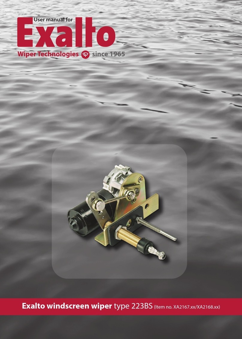
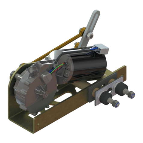
Exalto 232BD User manual

Quality Marine Equipment
Type: 232BD
Exalto windshield wiper
Cat. nos. 2157.30/32/35/40/45/50 (12V) - 2158.30/32/35/40/45/50 (24V)

Safety
Exalto windshield wipers are easy to install, yet a fair amount of technical
knowledge (mechanical and electrical) is required of the installer. Please
consult the manual or contact your vendor in case of doubt during installation
or malfunctioning.
Safety symbols
An exclamation mark in front of the text warns you, that injury or damage can
occur if a procedure is badly performed.
Dangers
The installation and use of Exalto wipers will not inflict any personal dangers or
damage, provided that installation is done according to the procedures
specified in the manual.
• Neverremovecoversorothersafetyprovisions,unlessmaintenanceisbeing
performed and all safety requirements are obeyed.
• Theinstallermustprovideallnecessarycovers.
• Alwaysdisconnecttheelectricalcircuitwhenperformingmaintenance.
Prevent the installation from being started (accidentally) by others.
Safety provisions
The safety provisions will protect the user against contact with moving,
electrical or hot parts. Some of them have to be provided by the installer. There
are several safety provisions:
• Coverorpanel(obligatory):coversmovingpartsandelectricalconnections.
The installer MUST provide a self-made cover or place the wiper behind a
panel.
• Makesurethewiperhasenoughventilationwhenplacingitbehindapanel
or cover.
• Placeafuse(seespecifications)inthemaincable.
Safety requirements
Before the Exalto wiper is installed, we strongly recommend the following:
• Readtheentiremanualbeforeinstallation.
• Makesureyourworkingenvironmentaswellasthewiperpartsareclean.
• Checktobesurenopartsaremissingordamaged.
• Useonlyhighqualitytoolsandhavethemwithinreachwheninstalling.
• Handlethepartswithcare.
2
!
!
!

• Neverinstallormaintainthewiperwiththeelectricalvoltageapplied,unless
this is specifically mentioned in the manual.
• Clearyourtoolsafterinstallation.
Use of the manual
Readtheentiremanualbeforeinstallation.Inthismanualyoucanfindthe
following expressions and symbols:
Hint!
Gives you advice on how to perform a task more easily.
Attention!
Alerts you to possible problems and safety warnings.
3
!

Contents
1 Introduction ........................................................... 5
1.1 Introduction ...................................................... 5
1.2 Environmental factors ............................................. 5
1.3 Modified use and guarantee conditions ............................ 5
2 Technical data ......................................................... 6
2.1 General ........................................................... 6
2.2 Electrical data 12 Volt.............................................. 6
2.3 Electrical data 24 Volt.............................................. 6
2.4 Mechanical data................................................... 6
3 Installation ............................................................ 7
3.1 Preparation ....................................................... 7
3.2 Installationofmechanicalparts .................................... 7
3.3 Electrical installation .............................................. 8
3.4 Final installation................................................... 9
4 Operation and use....................................................11
4.1 Preparation for first use...........................................11
4.2 Use ..............................................................11
5 Maintenance..........................................................12
5.1 General maintenance.............................................12
5.2 Servicing.........................................................12
5.3 Changing the wipe arc and park position..........................12
5.4 Roughdeterminationofwipearcandwiperblade.................13
5.5 Disassembly and assembly .......................................14
6 Troubleshooting......................................................15
7 Declaration of conformity ............................................16
8 Parts list ..............................................................17
9 Drawings and schemes ...............................................18
9.1 Assembly overview...............................................18
9.2 Internalwiringdiagram...........................................19
4

1 Introduction
With this user manual we want to guide you
in the installation and use of the Exalto
windshield wiper. Please follow all
instructions and install all safety provisions.
1.1 Introduction
Exalto windshield wipers are especially
designed to keep working even with the
most extreme weather conditions at sea. All
external parts are made of corrosion resistant materials. The housing of the
self-lubricating bearings is made of bronze.
Wiper type 232BD is designed to be mounted in the bulkhead or in the glass
window. The wiper arc is adjustable from 40° to 90° with steps of 5°. Standard
the 232BD is supplied for a bulkhead thickness of either 20, 35, 55, 75, 100 or
125. The matching Exalto PU pantograph arms are adjustable in length, to set
the wipe area accurately. The motors of the 232BD have insulated earth return.
1.2 Environmental factors
Inthewiper,materialsareusedthatareharmfulfortheenvironment(e.g.
copper).Thepartsofthewipercanbere-usedorrecycled.Noharmful
substances are disseminated when using or disassembling the wiper.
1.3 Modified use and guarantee conditions
All modifications or defects in the product are subject to the Orgalime General
Conditions of Sale. Please contact your vendor in case of any questions or if you
want to use Exalto wipers in a non-maritime environment or other applications.
5
!

2 Technical data
2.1 General
• Product ........................................ Exalto windshield wiper
• Types............................................ 232BD –12 and 24 Volt
• Cataloguenumbers12V ....................... 2157.30/32/35/40/45/50
• Cataloguenumbers24V ....................... 2158.30/32/35/40/45/50
2.2 Electrical data 12 Volt
• Torque(max.).....................................................32Nm
• Voltage...........................................................12 Volt
• Current.............................................................3.0 A
• Powerconsumption(max.)..........................................36 W
• Numberofrevolutions ......................... Low 38 rpm, high 56 rpm
• Recommendedcable .................5 wires, 1½ (16 g) or 2½ mm2(14 g)
.....................................................up to 10 m long
• Recommendedfuse .......................................6 A slow blow
• Grounding ........................................Insulatedearthreturn
Electrical data 24 Volt
• Torque(max.)....................................................32Nm
• Voltage.......................................................... 24 Volt
• Current............................................................ 1.5 A
• Powerconsumption(max.)......................................... 36 W
• Numberofrevolutions ......................... Low 38 rpm, high 56 rpm
• Recommendedcable ................ 5 wires, 1½ (16 g) or 2½ mm2(14 g)
.....................................................up to 10 m long
• Recommendedfuse ...................................... 4 A slow blow
• Grounding .........................................Insulatedearthreturn
2.3 Mechanical data
• Dimensions............................... l x w x h = 196 x 104 x 119 mm
• Shaftdiameters................. Drive shaft Ø 20 / support shaft Ø 8 mm
• Mounting ....................................Through glass or bullkhead
• Bearing..................................Bronze housing, self-lubricating
• Wiperarms...................................... Model PU up to 750 mm
• Wiperblades .............................................. Up to 800 mm
• Wipearc...........................Wipe arc disc 40°-90° adjustable per 5°
• Weight ................................................... approx. 2.5 kg
6

3 Installation
Readthechapteronsafety.Checkbeforeinstallationifthepartsareallpresent
andundamaged.Incaseoferrors,contactyourvendor.
3.1 Preparation
The complete wiper, with packaging, can be handled and transported by hand.
Leave the wiper in the packing, until you are ready to install it; this to reduce
the risk of damage. Make sure all parts, tools and other means are ready.
3.2 Installation of mechanical parts
1. Ifyourwiperissuppliedwiththewipearcdiscuninstalled,pleasefollow
steps described in paragraphs 5.3 and 5.4 to set the wiping arc prior to
installation.
Determine the place where the wiper is to be installed. The dimensions are
shown below. The wiper can be installed in any position.
7

Attention!
When installing the wiper, reserve space for a housing or cover.
2. Place the windshield wiper in the pre-drilled holes of the bulkhead (see
figure). A nitrile plate must be placed at both sides of the bulkhead.
Attention!
Do not fit the wiper arm before finishing the electrical connections.
3.3Electrical installation
3. Installawiperswitchinthedashboard.
Wiring diagram 232BD
8
!
!

Tightening torque: 16.3Nm / 12ft.lbs
tape
4. Connect the wiper to the ship’s electrical installation; see the diagram
above (or refer to paragraph 9.2 for full details on the wiring). Use a cable
with 5 wires with diameter of at least 1½ mm2(16 g) up to a maximum
length of 10 m. Use larger diameters when using longer cables.
5. Fit a slow blow fuse of 6A(12Volt), 4A (24 Volt) in the main cable.
6. Connect the switch to the wiper (refer to that specific manual for
installation).
3.4 Final installation
7. Switch on the power and test the motor briefly. Wait until the motor stops
after turning off the switch. The motor will be in park position. The
standard park position is shown in the figure under point 8.
Hint!
If you have doubts regarding the park position,
make a vane with tape to simulate the position of
the arms.
Attention!
The 232BD is suitable for wiper arms model PU up to
750 mm and wiper blades up to 800 mm.
8. Place the wiper arm with the blade on the
shafts. Fasten the nuts loosely onto the shafts.
9
!
!

Attention
To ensure the arm has the right spring pressure, install the wiper arm in such a way
that the shafts make a 90° angle with the window (figure left) and that the shafts
make a 90° angle with the wiper arm (figure right). If this is not the case, please
install a spacer or multiple spacers to make the 90° angles.
9. Switch on the power and test the motor briefly again to check the wiped
area.
10. Ifthewipearciscorrect,adjustthepositionandthelengthofthearmif
necessary. Tighten the nuts properly now.
10
!

4 Operation and use
4.1 Preparation for first use
Ifthewiperhasbeeninstalledandadjusted,thesystemcanbepreparedfor
first use. We recommend a thorough inspection of the system to ensure proper
operation.
Check:
• iftherearenoleakswheretheshaftsgothroughthebulkheadorglass;
• ifthewipearccleanstheentirewindow;
• iftheparkpositioniscorrect.
Ifthewipearcortheparkpositioniswrong,adjustthem.Followtheprocedure
in paragraph 5.3 to do so.
4.2 Use
All Exalto windshield wipers are provided with the following functions:
• lowspeed;
• highspeed;
• selfparking.
Do not use the wiper on a dry window; excessive wear of the blades and the
motor can occur in this case. Clean the wiper arm frequently with fresh water
(see also paragraph 5.1).
Because of the big variety of wiper switches, we refer to the user manual of the
installed switch to learn about the functions of that specific switch.
11

5 Maintenance
5.1 General maintenance
To keep the Exalto wiper in good condition, you are advised to:
• cleanwiper,armsandbladeswithfreshwateraftereveryjourneyinsaltwater
(to prevent salt from clogging moving parts);
• neverusethewiperonadrywindow.
5.2 Servicing
As long as the wiper system functions normally and is kept in good shape (see
paragraph 5.1), servicing the motor is not necessary. Check yearly (monthly
whenusedintensively)ifthewiperbladesareworn.Replacebladeswhenworn
orwhenthebladesleavemanystripesacrosstheglass.Incaseoffailureor
adjustments,haveservicingdonesolelybyqualifiedmechanics.Inchapter6,
‘Troubleshooting’, a listing is given of possible problems and their solutions.
5.3 Changing the wiping arc and park position
Ifthewipedareaisnotoptimum,youcanresetboththeangleandthepark
position.
5.3.1 Setting wiping arc
1. Disconnect the power supply!
2. Removethewiperfromthebulkheadandopenthehousing(see5.5.2).
3. Removethewipingarcdiscfromthemotorshaft.
4. Push the pin in the hole of the disc with the correct wiping arc (see 5.4).
5. Screw the M10 nut onto the pin and fasten properly, but not too tight (max.
9.78Nm/7.21ft.lbs)topreventdamagingthebearing.
6. Slide the connection lever onto the pin and secure it by inserting the
retaining ring in the groove of the pin.
7. Runthemotorbrieflytoreachparkingposition.
8. Push the disc on the motor shaft in the desired parking position (see 5.3.2).
5.3.2 Setting parking position
1. Place the wiping arc disc onto the motor shaft in standard or alternative
setting.
2. Make sure the disc is put
on in a way that the
connection lever is in an
almost straight libne wit
the pin and the centre
hole of the arc disc (see drawings).
12
Standard setting
parking position
Alternative
setting

EXAMPLE
1000
900
800
700
600
500
400
300
300
400
500
600
700
800
900
1000
1100
1200
1300
1400
40°
45°
50°
55°
60°
65°
70°
75°
80°
85°
90°
Wipe arc
Armlength (L)
Wiped area width (W)
Determination of wipe arc
Units in mm
L
D
E
GH
GW
W
H
D= distance top side
glass to center
of spindles
E= eye level
GH = glass height
GW = glass width
H= vertical displacement
L= length of arm
W= width of wiped area
Pin
Nut for pin
Bearing
Center nut for disc
Retaining ring
Connection lever
Disc
3. Screw M8 center nut for disc onto the motor shaft and tighten properly.
4. Mount the wiper assembly.
5. Runthemotorforafewminutestocheckifeverythingisworkingcorrectly.
6. Set the length of the wiper arm, if necessary.
5.4 Rough determination of
wipe arc and wiper blade
With this method the wipe arc and the
wiper blade length can roughly be
determined. Please contact your vendor
to calculate your configuration more
accurately.
• Determinelengthofpantographarm
(L): L = E + D
• getthemaximumwipedareawidth
(W): W = ±0.9 * GW
• findtheintersectionofLandWinthediagrambelow;
• thewipearc-lineclosesttotheintersection,showsthewipearc;
13

90°
86
103
117
132
146
161
176
190
205
220
234
249
264
278
293
263
250
105
85°
92
79
119
132
145
158
197
184
171
210
223
236
94
80°
82
70
105
117
129
140
175
164
152
187
199
211
222
234
83
75°
73
62
93
104
114
124
155
145
135
165
176
186
196
207
73
70°
63
55
81
90
100
109
136
127
118
145
154
163
172
181
63
65°
55
47
71
79
86
94
117
110
102
125
133
141
149
157
54
60°
47
40
60
67
74
80
100
94
87
107
114
121
127
134
45
55°
40
34
51
57
62
66
85
79
74
90
96
102
107
113
36
50°
33
26
43
47
52
56
70
66
61
75
80
84
89
94
30
45°
27
23
35
38
42
46
57
53
50
61
65
68
72
76
25
40°
21
19
26
30
34
37
45
43
40
48
51
54
57
60
400
Armlength (L)
350
300
450
500
550
600
750
700
650
800
850
900
950
1000
Determining the vertical displacement of the wiper blade
Wipe arc
Vertical displacement of the blade (H)
Units in mm
• findinthetablebelowtheverticaldisplacementoftheblade(H);
• Nowthewiperbladelengthcanbecalculated:
Lengthofwiperblade=0.9*2*(E-H)
5.5 Disassembly and assembly
Prevent injuries when disassembling: disconnect the wiper from the power
supply. Keep all necessary tools within reach and remember the chapter on
safety. Provide well protected packaging, if you’re going to stock or transport
the wiper assembly.
5.5.1 Removing the wiper assembly from the bulkhead
1. Disconnect all the electric connections of the wiper.
2. Removethewiperarms.
3. Removethenutsandplatesontheoutside.
4. Removethewiperfromtheholesinthebulkhead.
5. Ifyouwanttoreplacethewiper,followchapter3.
5.5.2 Disassembling the wipe arc disc
1. Disconnect all the electric connections of the wiper.
2. Removethewiperfromthebulkhead;(see5.5.1).
3. Unscrew the nut on the motor shaft and remove the disc.
4. For adjusting the wipe arc and replacing, follow section 5.3.
5.5.3 Removing the motor from the wiper assembly
1. Disconnect all the electric connections of the wiper.
2. Removethewiperarms.
3. Disassemble the wipe arc disc (see 5.5.2).
4. Unscrew the motor and remove it.
5. When replacing, screw the motor on the housing. Follow section 5.3 to
install the wipe arc disc in the correct position.
14
!

6 Troubleshooting
Inthischapter,severalmalfunctionsarementionedcombinedwithpossible
causes. Please leave servicing to qualified mechanics.
6.1 Wiper does not work after switching on
• Possiblecauses:
1. Wiper switch is not working properly.
2. Burned or incorrectly sized fuse.
3. Electrical connections are wired incorrectly or might be damaged.
4. The wiper motor has failed.
• Solutions:
1. Test and replace it. Check if the current is (and keeps being) too high.
2. (See solution 1).
3. Measure the voltage across the motor and check all connections if there is
none.
4.Replacethemotorandcheckfordragorahighcurrent.
6.2 Wiped area or park position is not correct
• Possiblecauses:
1. The wiper arms were placed without parking the motor first.
2. The wipe arc is set wrong or changed due to high loads (e.g. spring
pressure of arms too high, drag).
3. The wires are connected incorrectly.
• Solutions:
1.Removethewiperarms.Runthemotorshortlytoparkitandre-installthe
arms according to chapter 3.
2. Determine the wipe arc if needed (see section 5.4) and set the wipe arc
again (see chapter 5.3).
3. Check and reconnect the wiring (see the scheme in section 3.3).
6.3 Motor runs, but arms do not move
• Possiblecauses:
1. Mechanical joints are loose.
2. Parts are broken.
3. Grooves of shafts are worn.
• Solutions:
1.Checkifthearmsarewellfastened.Ifnot,openthehousing(follow
chapter 5) and check all joints and parts to see if they are loose, broken or
worn.
15
!

7 Declaration of conformity
MANUFACTURER’SDECLARATION
InaccordancetoAppendixIIsubBofDirective89/392/EEG(Machines)
Exalto B.V.
Nijverheidsstraat12
3371XEHardinxveld-Giessendam
TheNetherlands
Tel: +31 (0)184-61.58.00
Fax: +31 (0)184-61.82.00
hereby declares that
Exalto windshield wiper type 232BD
... is intended to be built into another machine or as a component, or is to be
integrated with other machines to a machine where Directive 89/392/EEG
applies to;
... does not fully comply to the requirements of mentioned Directive;
... complies to the following harmonised standards:
Pleasure yachts
• NEN-EN-ISO10133Extra-lowvoltageD.C.installations(1997)
(regarding color codes)
…and declares that the sub-assembly in question shall not be set into
operation until the complete machine, into which the sub-assembly is fitted,
shall be complete and conforms to all aspects of Directive 89/392/EEG.
Hardinxveld-Giessendam
7-3-2012 (m-d-y)
16

8 Parts list
No Qua Part Dimensions Cat. no.
1 1 Motor 2100.3024 /
2100.3012
2 3 Socket screw s.s. M6 x 35 2100.055
3 1 Housingmotorside 180 x 96 x 22 2100.902
4 3 Socket screw s.s. M6 x 16 2100.050
5 1 Pin M8 x 26 2100.920
6 1 Arc disk Ø70 x 5 2100.930
6A 1 Arc sticker 2100.931
7 1 NutM10x6.5s.s. M10 x 6.5 2100.354
8 1 Bearing Ø13 x 14 2100.926
9 2 Flat nut s.s. M8 x 4 2100.760
10 2 Retainingring 2197.097
11 1 Housingdriveside 180 x 96 x 22 2100.901
12 1 Support spindle bulkhead 20 mm M8 x 70 2100.446
Support spindle bulkhead 35 mm M8 x 90 2100.441
Support spindle bulkhead 55 mm M8 x 110 2100.447
Support spindle bulkhead 75 mm M8 x 130 2100.448
Support spindle bulkhead 100 mm M8 x 155 2100.449
13 2 Rubberlockingplate 2100.495
14 1 Nuts.s. M20 2100.460
15 1 Locknut s.s. M8 2100.071
16 1 Weathercap Ø26 x 20 2100.361
17 2 NutM20s.s M20 2100.350
18 1 S.s. plate 2100.485
19 1 Locking ring Ø12 x 4 2100.410
20 2 Rings.s. 18 x 12 x 1 2100.400
21 1 Bearing shell complete bulkhead 20 mm M20 x 65 2100.326
Bearing shell complete bulkhead 35 mm M20 x 80 2100.321
Bearing shell complete bulkhead 55 mm M20 x 100 2100.327
Bearing shell complete bulkhead 75 mm M20 x 120 2100.328
Bearing shell complete bulkhead 100 mm M20 x 145 2100.329
22 1 Bearing 2100.925
23 1 Linking lever 110 x 24 x 12 2100.936
24 1 Shaft bulkhead 20 mm Ø12 x 102 2100.364
Shaft bulkhead 35 mm Ø12 x 117 2100.360
Shaft bulkhead 55 mm Ø12 x 137 2100.366
Shaft bulkhead 75 mm Ø12 x 157 2100.368
Shaft bulkhead 100 mm Ø12 x 182 2100.370
17

1
2
3
4
5
6/6A
7
8
9
9
10
11
12
13
13
14
15
17
19
20
21
10
17
22
24
16
18
20
23
25 1
24 1
Wisas Ø12 + lever st38 wd= 35
STD 2100. 360
AISI 316 Annealed
Stainless Steel Bar (SS)
0.15
23 1
Dogbone (85)
STD 2100.936
Material <not specified>
0.04
22 1
Glijlager GFM0810-14 Kraag13x4
STD 2100.925
lxbxh or ODxIDxL
POM Acetal Copolymer
0.00
21 1
Draadbus M20×1mm wd= 35 mm
STD 2100. 321
Material <not specified>
0.11
20 2
Vulring 12 x 18 x 1 mm
STD 2100.400
1.4401 - SS316
0.00
19 1
Asborgring Ø12mm din471 STD 2100.410
1.4401 - SS316
0.000
18 1
RVS Sluitplaat 223BS 50mm
STD 2100.481
1.4401 - SS316
0.04
17 2 Moer M20×1
STD 2100.350
1.4401 - SS316
0.02
16 1
Stofkap rubber Ø26
STD 2100.361
Rubber
0.00
15 1
Borgmoer M8 A4
STD 2100.071
AISI 316 Annealed
Stainless Steel Bar (SS)
0.01
14 1 Moer M8
STD 2100.460
1.4401 - SS316
0.01
13 2
Sluitplaat Nitril 223BS 50mm
STD 2100.491
NBR
0.00
12 1
35mm
STD 2100
AISI 316 Annealed
Stainless Steel Bar (SS)
0.03
11 1
Ruitenw.behuizing helft wisaszijde Default
STD 2100.901
1060 Alloy
0.45
10
9 1
Moer M10 sw13
STD 2100.354
SW=13 H=6,500
1.4401 - SS316
0.00
8 1
Moer M8 plat din439 A4
STD 2100.760
1.0577 - S355J2
0.00
7
6 1
Wishoekschijf t.b.v.235KK/KD/KG/KJ/DE/BD
2100.930
5
4 3
Verzonken schroef M6× 16
STD 2100.050
1.4401 - SS316
0.00
3 1
Ruitenw.behuizing helft motorzijde Default
STD 2100.902
1060 Alloy
0.44
2 3
Verzonken schroef M6× 35
STD 2100.055
1.4401 - SS316
0.01
1 1
Exalto XP2 motor 24Volt 30Nm Default
STD 2100.3024
Material <not specified>
3.95
Pos.
Default
/QTY.
Description
PartNo / Note
Type / Size
Material
Weight
9 Drawings and schemes
9.1 Assembly overview
18

black
white
yellow
red
blue
+
-
0 1 2
L
P
B
H
9.2 Internal wiring diagram
The following diagram explains the way the wiper motor works.
Wiring diagram
Function Polarity Motor code Switch code Cable
high speed + 53b Hwhite
low speed + 53 L yellow
earth - 31b black
common leg 53e P blue
self parking + 53a B red
19

Exalto B.V.
•
P. O. Box 40
3370 AA Hardinxveld-
Giessendam
T
he Netherlands
•
T +31 (0)184 615 800
•
F +31 (0)184 618 200
•
E wipers@exalto.com
• I www.exaltowipers.com
© Exalto B.V. 07-2012
Table of contents
Other Exalto Marine Equipment manuals