NKE Pad Display Instruction Manual
Zi de Kerandré – Rue Gutenberg – 56700 – HENNEBONT
www.nke-marine-electronics.fr
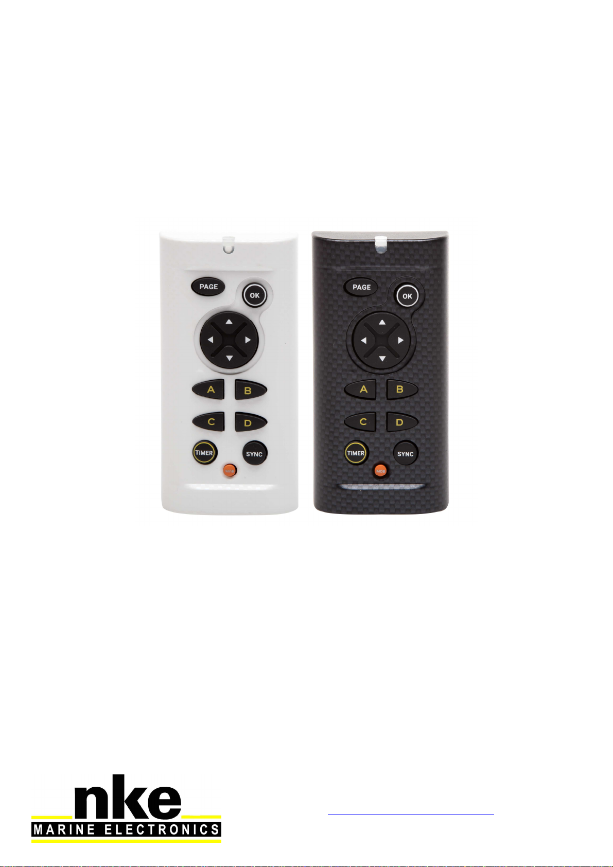
Pad Display
Part number: 90-60-545 Pad Display White
90-60-546 Pad Display Carbon
User Guide
&
Installation manual
V1.3

2 67_Pad_Display_UM_UK_13
1.
introduction.......................................................................................................... 3
2.
operation ............................................................................................................. 3
2.1
Key pad description....................................................................................... 3
3.
Settings of the Pad Display ................................................................................. 5
3.1
Set up an address for the Pad Display.......................................................... 5
3.2
Key sound ..................................................................................................... 5
4.
Use in a topline Bus............................................................................................. 6
4.1
Select of a display ......................................................................................... 6
4.2
Shortcut Pages A, B, C, D............................................................................. 7
4.3
Timer............................................................................................................. 7
4.3.1
Key TIMER and SYNC............................................................................ 7
4.3.2
Key OK (T1 et T2)................................................................................... 8
5.
Installation........................................................................................................... 9
5.1
Pad Display packing list................................................................................. 9
5.2
Wiring the Pad Display.................................................................................. 9
5.3
Mounting the Pad Display............................................................................ 10
6.
Specifications of the Pad Display ...................................................................... 11
7.
Firmware evolution for the pad Display ............................................................. 12

3 67_Pad_Display_UM_UK_13
1. INTRODUCTION
The Pad Display is a control for the Topline Bus. It is used to control Multidisplay,
Multigraphic displays, to manage the timer and the display standby control.
2. OPERATION
The Pad Display is given a node address, like a display. When the Pad Display is
powered for the first time, the default address is 0 (factory setting). It will be
necessary to define a node address for the Pad Pilot to be recognised and to operate
on the Topline Bus.
2.1 Key pad description
The Pad Display has 10 keys. They are used to control the display, to access the
menu, manage the Display and the Timer.
SYNC
OK
TIMER
PAGE
NAVIGATEUR
SHORTCUT PAGES
MOB
RED LED

4 67_Pad_Display_UM_UK_13
•RED LED
Led indicating the current mode for the Pad Display (display selection mode,
set-up mode)
Flashes at each press.
•PAGE
Use this key to navigate in various displays of the Topline range. Press and
hold to access the display selection mode.
This key is also used to access the displays' menus, to scroll the pages and
for the "back/return" function.
Press and hold (at least 3 seconds) to open the Menu page.
•OK
This key is used to confirm a selection.
Press and hold (at least 3 seconds) to open the settings page for
backlighting.
•NAVIGATEUR
Use the left and right arrows to select the display. It is also used to navigate in
the menus and pages of the selected display.
•RACCOURCIS PAGES (A, B, C, D)
Keys A, B, C, D are used to call up programmed pages or the standby
command for Multigraphic and Multidisplay displays.
•TIMER
To Launch and stop timer
•SYNC
To synchronize the timer

5 67_Pad_Display_UM_UK_13
•MOB
Press and hold this key to trigger a Man Over Board function on the Topline
bus.
3. SETTINGS OF THE PAD DISPLAY
3.1 Set up an address for the Pad Display
When the Pad Display is powered for the first time, the default address is 0, the LED
flashes once per second, waiting for the operational node address. Press to
allocate an address.
If the Pad Display already has an address, there are two possibilities:
You wish to allocate a new address:
Press + simultaneously until you hear an audible signal (3
seconds) and the LED flashes once per second. You’ve accessed the setup
mode. To allocate a new address, press .
You wish to set reset the default address (0):
To do this, press + simultaneously during 3 seconds, until you
hear an audible signal and the LED flashes once per second. The address 0 is
allocated to the Pad Display by pressing . This restores the setup as it
was when the device was powered for the first time.
3.2 Key sound
Every time you press on a key on Pad Display, this generates a sound. This sound
can be disabled by entering the setup mode with + during 3 seconds
until you hear a Beep and then press the right arrow of . Repeat the procedure to
activate the key sound.

6 67_Pad_Display_UM_UK_13
4. USE IN A TOPLINE BUS
4.1 Select of a display
To select a display with the Pad Display, press until the second beep (5
seconds). You’ve accessed the selection mode. Then press on the left or right arrow
to toggle between displays. You may press several times until you find the desired
display.
This operation is required on the first use, as by default no display
is selected.
- Selecting TL25:
Press on until the second beep, then with and left and right arrows
you can select the TL25. Once the TL25 is selected, the upper line flashes. Press
to confirm this display is selected. Then you can modify the upper line using
up and down arrows of . To change line, use . Press and long hold
to access the sub-channel. Press to change the sub-channel. Press and hold
long to exit.
- Selecting Multigraphic:
Press until you hear a second beep and choose a display using the left and
right arrows of : Once Multigraphic has been selected, a remote control (version
2.3) or a yellow box (version 2.4) appears, then press to confirm. The keypad
works the same way as the one on the Multigraphic.
Refer to the manual of Multigraphic V2.4 or newer.
- Selecting Multidisplay:
Press until you hear a second beep and choose a display using the left and
right arrows of : Once the Multidisplay has been selected, a yellow box appears
and press to confirm.
Refer to the Multidisplay manual.

7 67_Pad_Display_UM_UK_13
4.2 Shortcut Pages A, B, C, D
Keys A, B, C, D are used to call up programmed pages or the standby command in
the Multigraphic and Multidisplay displays.
Example: I have a Pad Display, a Multidisplay and a Multigraphic in my Topline
installation. My two displays have the A key programmed. When I press the A key on
my Pad, I bring up the programmed page of each display. For the display standby
command, pressing once switches the display to standby and then waking it up.
4.3 Timer
4.3.1 Key TIMER and SYNC
TIMER and SYNC direct access to the timer. For pressing these keys to have an
effect it is necessary that:
A page with the TIMER channel has been created on at least one bus display.
That in the reactions to the SYNC shortcut the display of the page in question has
been programmed. Settings menu> Shortcut configuration> Sync shortcut - Goto
page X.
3 states for the TIMER :
1/ Not ready, no number is displayed ----
2/ Ready to launch. The time T1 is displayed.
3/ In process, the time decrease.
At first display the TIMER channel:
- To synchronize the TIMER, push longtime on , T1 is display.
- To change T1 push on one or many time.
- To launch TIMER push on .
- If you have delay, synchronize at the closest minute. Push .
Ex : If the TIMER display 1mn32 it will synchronize at 2mn and if the display
1mn24, it will synchronize at 1mn.
- To stop the TIMER push and push again for restart the TIMER.
- To prepare the TIMER push long time

8 67_Pad_Display_UM_UK_13
Once on the TIMER page you can also press to arm your TIMER via the menu.
(§4.3.2)
4.3.2 Key OK (T1 et T2)
When you select a Multidisplay or a Multigraphic with the PAD Display and you
display a page where the TIMER channel appears, pressing causes the
appearance of popup windows:
- First popup: "Arm TIMER T1". The TIMER channel displays the duration “T1”
configured in the “TIMER” sensor instead of the 4 lines indicating that the data is
empty.
- Second popup: "Start TIMER". The TIMER channel will count down the seconds
from T1.
- Third popup: "Synchronize T2". This allows for example to reset the stopwatch to a
phase of the procedure such as the preparatory signal at 4 minutes.
- Fourth popup: "Stop TIMER". This returns to the empty channel with 4 lines.

9 67_Pad_Display_UM_UK_13
5. INSTALLATION
WARNING
Turn the power supply OFF before doing any work on the TOPLINE Bus.
5.1 Pad Display packing list
- A Pad Display with a six meters cable.
- A protection cover.
- A Fixamo M14.
- A plastic M14 nut.
5.2 Wiring the Pad Display
Connect the bus cable to a Topline junction box as follow:
White wire on "+12 V white" or "+/white"
Shield on "GND" or "-/nu"
Black on "Data black" or "D/black"
Fixamo
Ecrou
plastique

10 67_Pad_Display_UM_UK_13
5.3 Mounting the Pad Display
There are several ways to mount the Pad Display:
An 18 mm diameter hole is required to allow the
cable running as well as the mounting kit.
If the supporting surface is between 1
and 3mm: Screw the plastic nut by hand.
If the supporting surface is between 3.1
and 40 mm: Screw by hand the Fixamo
to the unit and then the plastic nut.
Alternatively, you can use the two inserts
at the back of the Pad, and screw two
M3 screws.
11 67_Pad_Display_UM_UK_13
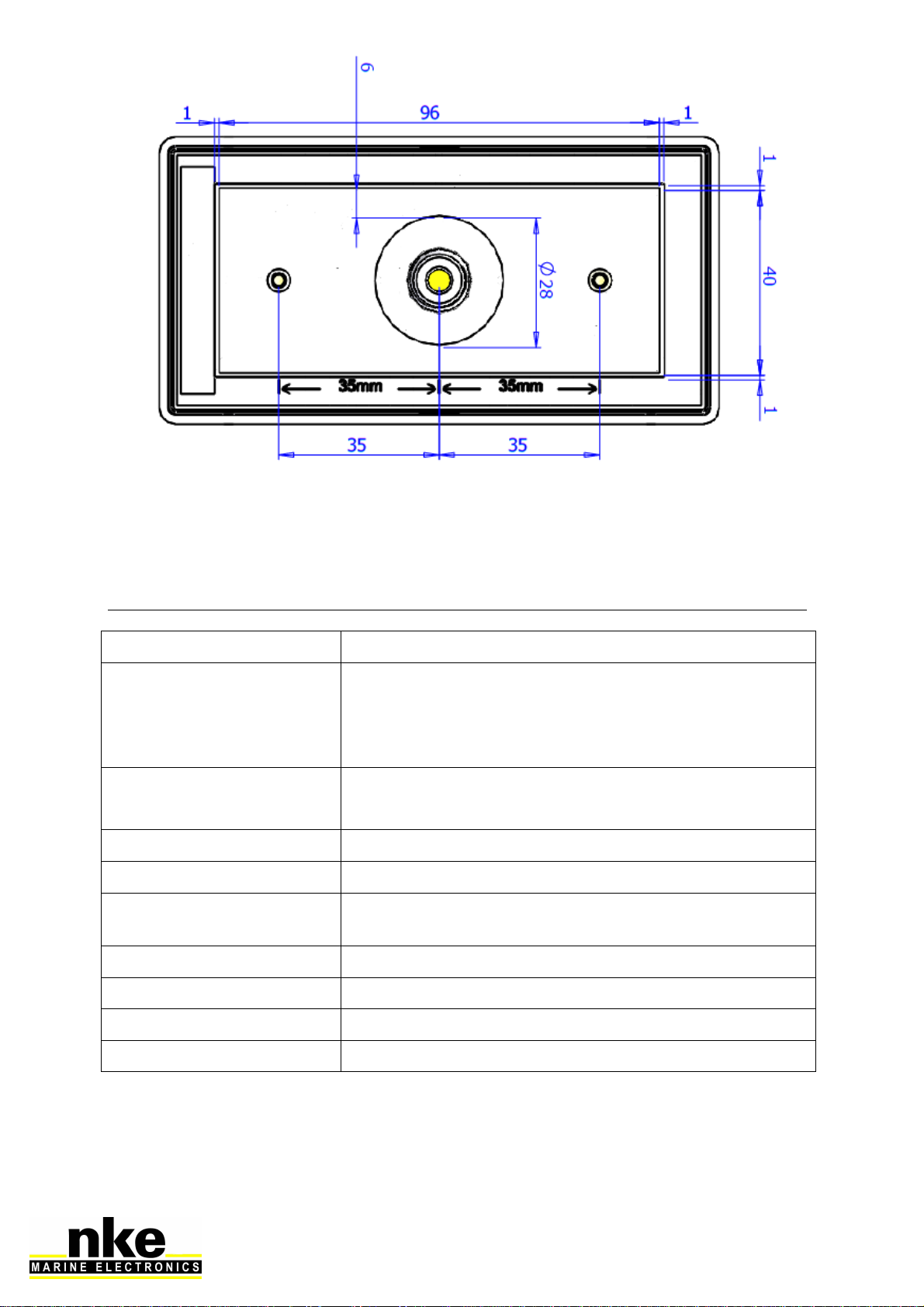
DRILLING TEMPLATE
6. SPECIFICATIONS OF THE PAD DISPLAY
Parameter Value
Dimensions
With protection cover (mm): 122 x 62 x 27
(Length x Width x Depth)
Without protection cover (mm): 115 x 58 x 23
(Length x Width x Depth)
Mounting kit - Hand-screw nut M14 (part Nr: 30-95-032)
- Fixamo M14 (part Nr: 30-95-031)
Weight 350g with 6m of cable (32g/m) and protection cover
Power supply 8V – 32V DC
Operational consumption
@ 12 V < 30mA
Topline bus power cable Ø5.5mm, 2 wires + ground, length 6m
Operational temperature -10°C / 50°C
Storage temperature -20°C / 60°C
Protection rate IP7 waterproof to water projections

12 67_Pad_Display_UM_UK_13
7. FIRMWARE EVOLUTION FOR THE PAD DISPLAY
REV
Date
Information
V1.0 21/06/2018
- Original version
V1.1 08/11/2018
- Bug correction for long auto shortcut
-
Possibility to acknowledge the TOPLINE Bus audible
alarms
- Compatibility with HR and Regatta processors
V1.2 11/03/2020
- Removal of standby of the pad
V1.3 09/07/2020
- Fixed address acquisition bug
This manual suits for next models
2
Table of contents
Other NKE Marine Equipment manuals


Popular Marine Equipment manuals by other brands

Marport
Marport Trawl Explorer Quick reference guide

Veratron
Veratron VMH 70 user manual

Bennett
Bennett H35 Series Maintenance manual

Glendinning
Glendinning Cablemaster User's installation and operation manual

Lewmar
Lewmar V1 Owners installation, operation & basic servicing manual

Venitem
Venitem DOGE AS1 Technical manual


