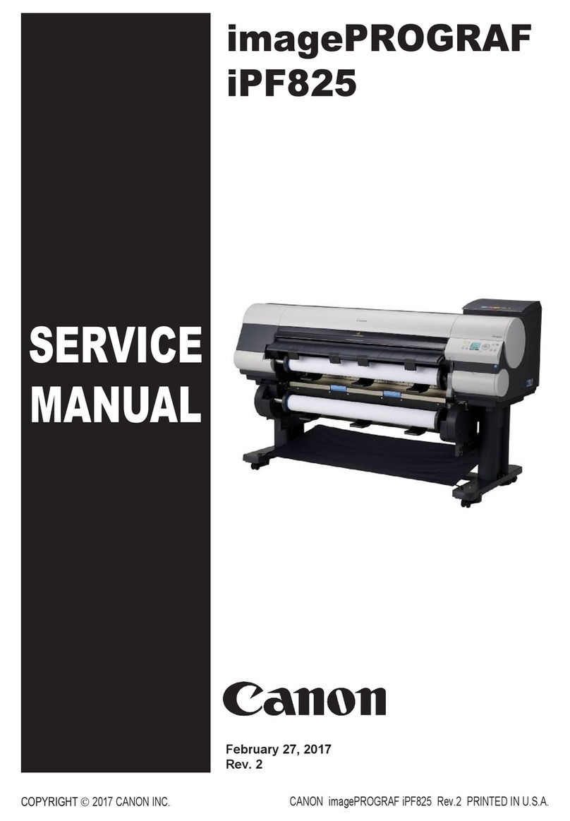
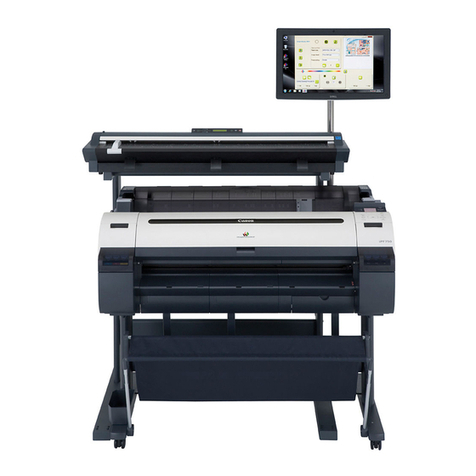
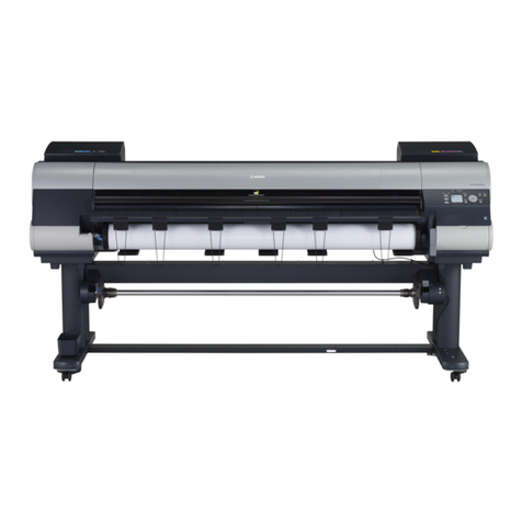
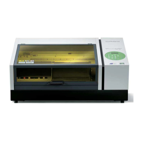
Canon iPF8000S - imagePROGRAF Color Inkjet Printer User manual

SERVICE
MANUAL
imagePROGRAF
iPF8000S
COPYRIGHT ©
2017 CANON INC. CANON imagePROGRAF iPF8000S Rev.1 PRINTED IN U.S.A.
February 27, 2017
Rev. 1


Application
This manual has been issued by Canon Inc. for qualified persons to learn technical theory, installation, maintenance, and repair
of products. This manual covers all localities where the products are sold. For this reason, there may be information in this
manual that does not apply to your locality.
Corrections
This manual may contain technical inaccuracies or typographical errors due to improvements or changes in products. When
changes occur in applicable products or in the contents of this manual, Canon will release technical information as the need
arises. In the event of major changes in the contents of this manual over a long or short period, Canon will issue a new edition
of this manual.
The following paragraph does not apply to any countries where such provisions are inconsistent with local law.
Trademarks
The product names and company names used in this manual are the registered trademarks of the individual companies.
Copyright
This manual is copyrighted with all rights reserved. Under the copyright laws, this manual may not be copied, reproduced or
translated into another language, in whole or in part, without the written consent of Canon Inc.
COPYRIGHT © 2001 CANON INC.
Printed in Japan
Caution
Use of this manual should be strictly supervised to avoid disclosure of confidential information.

Introduction
Symbols Used
This documentation uses the following symbols to indicate special information:
Symbol Description
Indicates an item of a non-specific nature, possibly classified as Note, Caution, or Warning.
Indicates an item requiring care to avoid electric shocks.
Indicates an item requiring care to avoid combustion (fire).
Indicates an item prohibiting disassembly to avoid electric shocks or problems.
Indicates an item requiring disconnection of the power plug from the electric outlet.
Indicates an item intended to provide notes assisting the understanding of the topic in question.
Indicates an item of reference assisting the understanding of the topic in question.
Provides a description of a service mode.
Provides a description of the nature of an error indication.
Memo
REF.

Introduction
The following rules apply throughout this Service Manual:
1. Each chapter contains sections explaining the purpose of specific functions and the relationship between electrical and mechanical systems with refer-
ence to the timing of operation.
In the diagrams, represents the path of mechanical drive; where a signal name accompanies the symbol , the arrow indicates the
direction of the electric signal.
The expression "turn on the power" means flipping on the power switch, closing the front door, and closing the delivery unit door, which results in
supplying the machine with power.
2. In the digital circuits, '1'is used to indicate that the voltage level of a given signal is "High", while '0' is used to indicate "Low".(The voltage value, how-
ever, differs from circuit to circuit.) In addition, the asterisk (*) as in "DRMD*" indicates that the DRMD signal goes on when '0'.
In practically all cases, the internal mechanisms of a microprocessor cannot be checked in the field. Therefore, the operations of the microprocessors
used in the machines are not discussed: they are explained in terms of from sensors to the input of the DC controller PCB and from the output of the
DC controller PCB to the loads.
The descriptions in this Service Manual are subject to change without notice for product improvement or other purposes, and major changes will be com-
municated in the form of Service Information bulletins.
All service persons are expected to have a good understanding of the contents of this Service Manual and all relevant Service Information bulletins and be
able to identify and isolate faults in the machine."


Contents
Contents
Chapter 1 PRODUCT DESCRIPTION
1.1 Product Overview .......................................................................................................................................1- 1
1.1.1 Product Overview....................................................................................................................................................1- 1
1.2 Features .....................................................................................................................................................1- 3
1.2.1 Features ..................................................................................................................................................................1- 3
1.2.2 Printhead.................................................................................................................................................................1- 3
1.2.3 Ink Tank...................................................................................................................................................................1- 3
1.2.4 Cutter Unit ...............................................................................................................................................................1- 4
1.2.5 Roll holder ...............................................................................................................................................................1- 4
1.2.6 Stand.......................................................................................................................................................................1- 4
1.2.7 Media Take-up Unit.................................................................................................................................................1- 5
1.2.8 Hard Disk Drive .......................................................................................................................................................1- 6
1.2.9 IEEE1394 (FireWire) Board.....................................................................................................................................1- 6
1.2.10 Consumables.........................................................................................................................................................1- 7
1.3 Product Specifications................................................................................................................................1- 8
1.3.1 Product Specifications.............................................................................................................................................1- 8
1.4 Detailed Specifications .............................................................................................................................1- 10
1.4.1 Print Speed and Direction......................................................................................................................................1- 10
1.4.2 Interface Specifications .........................................................................................................................................1- 16
1.5 Names and Functions of Components .....................................................................................................1- 17
1.5.1 Front......................................................................................................................................................................1- 17
1.5.2 Rear.......................................................................................................................................................................1- 18
1.5.3 Top Cover (Inside).................................................................................................................................................1- 19
1.5.4 Carriage.................................................................................................................................................................1- 20
1.5.5 Ink Tank Cover (Inside).........................................................................................................................................1- 21
1.6 Basic Operation........................................................................................................................................1- 22
1.6.1 Operation Panel.....................................................................................................................................................1- 22
1.6.2 Main Menu.............................................................................................................................................................1- 23
1.6.3 Basket Unit............................................................................................................................................................1- 44
1.7 Safety and Precautions ............................................................................................................................1- 50
1.7.1 Safety Precautions ................................................................................................................................................1- 50
1.7.1.1 Moving Parts..........................................................................................................................................................................1- 50
1.7.1.2 Adhesion of Ink ...................................................................................................................................................................... 1- 51
1.7.1.3 Electric Parts..........................................................................................................................................................................1- 53
1.7.2 Other Precautions..................................................................................................................................................1- 54
1.7.2.1 Printhead................................................................................................................................................................................1- 54
1.7.2.2 Ink Tank .................................................................................................................................................................................1- 55
1.7.2.3 Handling the Printer...............................................................................................................................................................1- 56
1.7.3 Precautions When Servicing Printer......................................................................................................................1- 58
1.7.3.1 Notes on the Data Stored in the Printer.................................................................................................................................1- 58
1.7.3.2 Confirming the Firmware Version ..........................................................................................................................................1- 58
1.7.3.3 Precautions against Static Electricity.....................................................................................................................................1- 58
1.7.3.4 Precautions for Disassembly/Reassembly.............................................................................................................................1- 58
1.7.3.5 Self-diagnostic Feature.......................................................................................................................................................... 1- 58
1.7.3.6 Disposing of the Lithium Battery ............................................................................................................................................ 1- 59
Chapter 2 TECHNICAL REFERENCE
2.1 Basic Operation Outline..............................................................................................................................2- 1
2.1.1 Printer Diagram .......................................................................................................................................................2- 1
2.1.2 Print Signal Sequence.............................................................................................................................................2- 2

Contents
2.1.3 Print Driving .............................................................................................................................................................2- 3
2.2 Firmware ....................................................................................................................................................2- 5
2.2.1 Operation Sequence at Power-on............................................................................................................................2- 5
2.2.2 Operation Sequence at Power-off............................................................................................................................2- 6
2.2.3 Print Control.............................................................................................................................................................2- 7
2.2.4 Print Position Adjustment Function........................................................................................................................2- 16
2.2.5 Head Management ................................................................................................................................................2- 16
2.2.6 Printhead Overheating Protection Control.............................................................................................................2- 16
2.2.7 Pause between Pages...........................................................................................................................................2- 16
2.2.8 White Raster Skip..................................................................................................................................................2- 16
2.2.9 Sleep Mode............................................................................................................................................................2- 16
2.2.10 Hard Disk Drive....................................................................................................................................................2- 16
2.3 Printer Mechanical System.......................................................................................................................2- 18
2.3.1 Outline....................................................................................................................................................................2- 18
2.3.1.1 Outline....................................................................................................................................................................................2- 18
2.3.2 Ink Passage...........................................................................................................................................................2- 19
2.3.2.1 Ink Passage...........................................................................................................................................................................2- 19
2.3.2.2 Ink Tank Unit..........................................................................................................................................................................2- 21
2.3.2.3 Carriage Unit..........................................................................................................................................................................2- 23
2.3.2.4 Printhead................................................................................................................................................................................2- 26
2.3.2.5 Purge Unit..............................................................................................................................................................................2- 27
2.3.2.6 Maintenance Cartridge...........................................................................................................................................................2- 31
2.3.2.7 Air Flow.................................................................................................................................................................................. 2- 32
2.3.3 Paper Path.............................................................................................................................................................2- 33
2.3.3.1 Outline....................................................................................................................................................................................2- 33
2.3.3.2 Paper Path............................................................................................................................................................................. 2- 34
2.3.3.3 Cutter Unit..............................................................................................................................................................................2- 35
2.4 Printer Electrical System ..........................................................................................................................2- 36
2.4.1 Outline....................................................................................................................................................................2- 36
2.4.1.1 Overview................................................................................................................................................................................ 2- 36
2.4.2 Main Controller.......................................................................................................................................................2- 38
2.4.2.1 Main controller PCB components ..........................................................................................................................................2- 38
2.4.3 Carriage Relay PCB...............................................................................................................................................2- 40
2.4.3.1 Carriage relay PCB components ...........................................................................................................................................2- 40
2.4.4 Head Relay PCB....................................................................................................................................................2- 40
2.4.4.1 Head relay PCB components................................................................................................................................................. 2- 40
2.4.5 Motor Driver...........................................................................................................................................................2- 41
2.4.5.1 Media take-up PCB components ...........................................................................................................................................2- 41
2.4.6 Maintenance Cartridge Relay PCB........................................................................................................................2- 41
2.4.6.1 Maintenance cartridge relay PCB components......................................................................................................................2- 41
2.4.7 Power Supply.........................................................................................................................................................2- 41
2.4.7.1 Power supply block diagram..................................................................................................................................................2- 41
2.5 Detection Functions with Sensors............................................................................................................2- 42
2.5.1 Covers....................................................................................................................................................................2- 42
2.5.2 Ink passage system...............................................................................................................................................2- 43
2.5.3 Carriage system.....................................................................................................................................................2- 45
2.5.4 Paper path system.................................................................................................................................................2- 47
2.5.5 Media take-up Unit.................................................................................................................................................2- 48
2.5.6 Others....................................................................................................................................................................2- 48
Chapter 3 INSTALLATION
3.1 Installation ..................................................................................................................................................3- 1
3.1.1 Making Pre-Checks..................................................................................................................................................3- 1
3.1.1.1 Making Pre-Checks..................................................................................................................................................................3- 1
3.1.2 Unpacking and Installation.......................................................................................................................................3- 2
3.1.2.1 Checking the Contents.............................................................................................................................................................3- 2
3.1.2.2 Assembling the Stand..............................................................................................................................................................3- 5
Contents
3.1.2.3 Installing the Printer.................................................................................................................................................................3- 8
3.1.2.4 Installing the Media Take-up Unit ..........................................................................................................................................3- 10
3.1.2.5 Installing the Basket...............................................................................................................................................................3- 16
3.1.2.6 Removing Protection Materials..............................................................................................................................................3- 20
3.1.3 Checking the Images/Operations..........................................................................................................................3- 22
3.1.3.1 Checking the Image and Operation.......................................................................................................................................3- 22
3.2 Transporting the Printer............................................................................................................................3- 23
3.2.1 Transporting the Printer.........................................................................................................................................3- 23
3.2.1.1 Transporting the Printer ......................................................................................................................................................... 3- 23
3.2.2 Reinstalling the Printer ..........................................................................................................................................3- 36
3.2.2.1 Reinstalling the Printer........................................................................................................................................................... 3- 36
Chapter 4 DISASSEMBLY/REASSEMBLY
4.1 Service Parts ..............................................................................................................................................4- 1
4.1.1 Service Parts...........................................................................................................................................................4- 1
4.2 Disassembly/Reassembly...........................................................................................................................4- 2
4.2.1 Disassembly/Reassembly .......................................................................................................................................4- 2
4.3 Points to Note on Disassembly and Reassembly.......................................................................................4- 5
4.3.1 Note: Items that should never be disassembled......................................................................................................4- 5
4.3.2 Moving the carriage manually..................................................................................................................................4- 5
4.3.3 Units requiring draining of ink..................................................................................................................................4- 5
4.3.4 External Covers.......................................................................................................................................................4- 6
4.3.5 Drive Unit...............................................................................................................................................................4- 14
4.3.6 Carriage Unit .........................................................................................................................................................4- 15
4.3.7 Ink Tube Unit.........................................................................................................................................................4- 20
4.3.8 Feeder Unit............................................................................................................................................................4- 22
4.3.9 Purge Unit..............................................................................................................................................................4- 23
4.3.10 Ink Tank Unit........................................................................................................................................................4- 24
4.3.11 Linear Encoder ....................................................................................................................................................4- 27
4.3.12 Head Management Sensor..................................................................................................................................4- 28
4.3.13 PCBs....................................................................................................................................................................4- 29
4.3.14 Opening the Cap and moving the Wiper Unit ......................................................................................................4- 30
4.3.15 Draining the ink....................................................................................................................................................4- 31
4.3.16 Opening and closing ink supply valves................................................................................................................4- 32
4.4 Applying the Grease.................................................................................................................................4- 33
4.4.1 Applying the Grease..............................................................................................................................................4- 33
4.5 Adjustment and Setup Items ....................................................................................................................4- 36
4.5.1 Adjustment Item List..............................................................................................................................................4- 36
4.5.2 Procedure after Replacing the Carriage Unit or Multi Sensor ...............................................................................4- 36
4.5.3 Procedure after Replacing the Feed Roller or Feed Roller Encoder.....................................................................4- 36
4.5.4 Procedure after Replacing the Head Management Sensor...................................................................................4- 36
Chapter 5 MAINTENANCE
5.1 Periodic Replacement Parts.......................................................................................................................5- 1
5.1.1 Periodic Replacement Parts....................................................................................................................................5- 1
5.2 Consumable Parts......................................................................................................................................5- 1
5.2.1 Consumable Parts...................................................................................................................................................5- 1
5.3 Periodic Maintenance.................................................................................................................................5- 2
5.3.1 Periodic Maintenance..............................................................................................................................................5- 2
Chapter 6 TROUBLESHOOTING
6.1 Troubleshooting..........................................................................................................................................6- 1
6.1.1 Outline.....................................................................................................................................................................6- 1
6.1.1.1 Outline of Troubleshooting.......................................................................................................................................................6- 1

Contents
6.2 Location of Connectors and Pin Arrangement ...........................................................................................6- 2
6.2.1 Main controller PCB.................................................................................................................................................6- 2
6.2.2 Carriage relay PCB................................................................................................................................................6- 12
6.2.3 Head relay PCB.....................................................................................................................................................6- 21
6.3 Version Up................................................................................................................................................6- 29
6.3.1 Firmware Update Tool ...........................................................................................................................................6- 29
6.4 Service Tools............................................................................................................................................6- 34
6.4.1 Tool List .................................................................................................................................................................6- 34
Chapter 7 SERVICE MODE
7.1 Service Mode .............................................................................................................................................7- 1
7.1.1 Service Mode Operation..........................................................................................................................................7- 1
7.1.2 Map of the Service Mode.........................................................................................................................................7- 2
7.1.3 Details of Service Mode...........................................................................................................................................7- 8
7.1.4 Sample Printout .....................................................................................................................................................7- 18
7.2 Special Mode............................................................................................................................................7- 22
7.2.1 Special Modes for Servicing ..................................................................................................................................7- 22
Chapter 8 ERROR CODE
8.1 Outline........................................................................................................................................................8- 1
8.1.1 Outline......................................................................................................................................................................8- 1
8.2 Warning/Error/Service Call Error................................................................................................................8- 2
8.2.1 Code Table ..............................................................................................................................................................8- 2

Chapter 1 PRODUCT DESCRIPTION


Contents
Contents
1.1 Product Overview ....................................................................................................................................... 1-1
1.1.1 Product Overview.................................................................................................................................................... 1-1
1.2 Features ..................................................................................................................................................... 1-3
1.2.1 Features .................................................................................................................................................................. 1-3
1.2.2 Printhead................................................................................................................................................................. 1-3
1.2.3 Ink Tank................................................................................................................................................................... 1-3
1.2.4 Cutter Unit ............................................................................................................................................................... 1-4
1.2.5 Roll holder ............................................................................................................................................................... 1-4
1.2.6 Stand....................................................................................................................................................................... 1-4
1.2.7 Media Take-up Unit................................................................................................................................................. 1-5
1.2.8 Hard Disk Drive ....................................................................................................................................................... 1-6
1.2.9 IEEE1394 (FireWire) Board..................................................................................................................................... 1-6
1.2.10 Consumables......................................................................................................................................................... 1-7
1.3 Product Specifications................................................................................................................................ 1-8
1.3.1 Product Specifications............................................................................................................................................. 1-8
1.4 Detailed Specifications ............................................................................................................................. 1-10
1.4.1 Print Speed and Direction....................................................................................................................................... 1-10
1.4.2 Interface Specifications .......................................................................................................................................... 1-16
1.5 Names and Functions of Components ..................................................................................................... 1-17
1.5.1 Front....................................................................................................................................................................... 1-17
1.5.2 Rear........................................................................................................................................................................ 1-18
1.5.3 Top Cover (Inside).................................................................................................................................................. 1-19
1.5.4 Carriage.................................................................................................................................................................. 1-20
1.5.5 Ink Tank Cover (Inside).......................................................................................................................................... 1-21
1.6 Basic Operation........................................................................................................................................ 1-22
1.6.1 Operation Panel...................................................................................................................................................... 1-22
1.6.2 Main Menu.............................................................................................................................................................. 1-23
1.6.3 Basket Unit............................................................................................................................................................. 1-44
1.7 Safety and Precautions ............................................................................................................................ 1-50
1.7.1 Safety Precautions ................................................................................................................................................. 1-50
1.7.1.1 Moving Parts........................................................................................................................................................................... 1-50
1.7.1.2 Adhesion of Ink ....................................................................................................................................................................... 1-51
1.7.1.3 Electric Parts........................................................................................................................................................................... 1-53
1.7.2 Other Precautions................................................................................................................................................... 1-54
1.7.2.1 Printhead................................................................................................................................................................................. 1-54
1.7.2.2 Ink Tank .................................................................................................................................................................................. 1-55
1.7.2.3 Handling the Printer................................................................................................................................................................ 1-56
1.7.3 Precautions When Servicing Printer....................................................................................................................... 1-58
1.7.3.1 Notes on the Data Stored in the Printer.................................................................................................................................. 1-58
1.7.3.2 Confirming the Firmware Version ........................................................................................................................................... 1-58
1.7.3.3 Precautions against Static Electricity...................................................................................................................................... 1-58
1.7.3.4 Precautions for Disassembly/Reassembly.............................................................................................................................. 1-58
1.7.3.5 Self-diagnostic Feature........................................................................................................................................................... 1-58
1.7.3.6 Disposing of the Lithium Battery ............................................................................................................................................. 1-59


Chapter 1
1-1
1.1 Product Overview
1.1.1 Product Overview
0014-8814
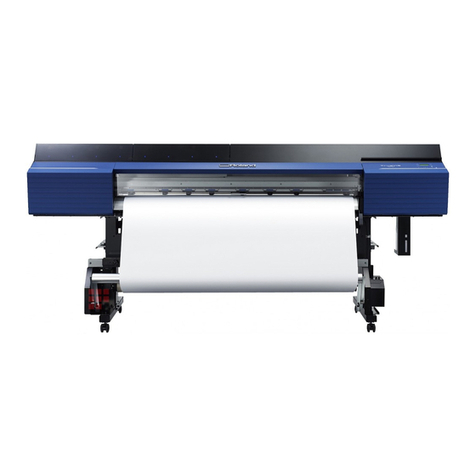
This printer is a large-format printer that prints in a maximum width of 44 inches with high-speed photographic picture quality.
This printer is a stand-mounted type printer and is capable of output to either roll media or cut sheet.
F-1-1
[10]
[3]
[4]
[5]
[6] [11]
[9]
[12]
[13]
[14]
[15]
[1]
[2]
[8]
[7]

Chapter 1
1-2
F-1-2
T-1-1
[1] Upper Cover [12] Stand
[2] Ink Tank Cover [13] Maintenance Cartridge Cover
[3] Ejection Slot [14] Maintenance Cartridge
[4] Ejection Guide [15] Operation Panel
[5] Output Stacker [16] Expansion Board Slot
[6] Roll Holder Slot [17] Ethernet Port
[7] Holder Stopper [18] USB Port
[8] Roll Holder [19] Accessory Pocket
[9] Paper Feed Slot [20] Media Take-up Unit Power Inlet
[10] Ejection Support [21] Power Supply Connector
[11] Release Lever [22] Carrying Handles
[18]
[19]
[20]
[21]
[17] [16]
[22]

Chapter 1
1-3
1.2 Features
1.2.1 Features
0017-8111
- Media pass in widths up to 44 inches (1117.6 mm).
- Large ink tanks reduce the need for frequent ink replacement.
- Uninterrupted printing from subtanks.
- BK and MBK inks are loaded concurrently to eliminate the need for their replacement.
- Media take-up unit (option) is supported.
- Media take-up unit (option) can be mounted concurrently with a basket.
- Durability will be added by maintenance kit.
- Large LCD panel displays more information and makes operations easier.
- High resolutions of 2400 x 1200 dpi maximum, coupled with the exceptionally light-fast, water-proof and ozone-proof 8-color pigment inks of MBK, BK, PC, C,
PM, M, Y and GY, deliver high-quality photographic picture quality.
- USB2.0 Hi-speed interface and 10Base-T/100Base-TX in standard support of a TCP/IP network, plus optional support of IEEE1394.
- Barcodes printed on roll media makes measuring the remaining roll length more manageable.
- Borderless four-side printing support (roll media) reduces laborious cutting work, easing the job of creating posters to a significant degree.
- High-speed printing with a 1-inch head for each color (1,280 nozzles), under bidirectional print control.
Functional enhancements new to this model include:
- Higher image quality
The color calibration feature adds to the faithfulness of color reproduction.
- Enhanced ease of operation
The hard disk is installed for better print job management and for driving on night time.
- High printing productivity
The 8-color pigment ink system offers enhanced printing productivity.
1.2.2 Printhead
0013-2742
The printhead that mounts on the carriage is an integrated six-color disposable printhead.
It has 2,560 nozzles for each color, comprising two rows of 1,280 nozzles each arranged in a staggerd pattern.
If print quality does not improve despite carrying out the specified cleaning, the printhead must be replaced with a new one.
F-1-3
1.2.3 Ink Tank
0017-8112
The ink tanks are disposable.
The ink tanks come with 8-colors: mat black(MBK), black(BK), photo cyan(PC), cyan(C), photo magenta(PM), magenta(M), yellow(Y) and gray(GY). Each of
these inks are pigment ink.
The ink tanks are also available in two capacities: 330 ml and 700 ml.
Each tank is furnished with a notch for preventing incorrect installation, which will allow the tank to be installed only at the position marked in the right color.
An ink tank should be replaced when an ink tank replacement prompt message appears.
F-1-4

Chapter 1
1-4
1.2.4 Cutter Unit
0013-6369
The cutter unit that mounts on the carriage unit is disposable.
Replace the cutter unit when it gets dull.
F-1-5
1.2.5 Roll holder
0013-6371
The printer comes with a roll holder for paper tubes having an inside diameter of 2 inches as standard. It supports an optional roller holder for paper tubes having
an inside diameter of 3 inches.
Both roll holders clamp the paper tubes of roll media with an outside diameter of 150 mm or less from inside.
F-1-6
1.2.6 Stand
0017-8299
The stand is equipped with casters so that the printer can be easily moved.
F-1-7
[1] Stand [2] Stopper
O N
[2]
[1]

Chapter 1
1-5
1.2.7 Media Take-up Unit
0014-8824
Media take-up unit
The Media Take-up unit spools the 2 or 3 inch core, the roll media (17" to 44"), after it is printed by the host computer.
Take-up begins once the falling paper is detected by the Media take-up paper detection sensor, attached to the weight roller.
The roll media may also be manually spooled, using the button on the media take up unit.
The media take-up unit has an overload protection feature to prevent accidents while spooling rolls. (This feature will disable the motor automatically when an
overload occurs while spooling a roll.)
Additional features of the media take-up unit include:
- An adapter may be installed to support a 3-inch paper tube.
- Roll media can be unwound by feeding them backwards to visually check the images.
- Weight rollers varying in length to suit specific roll widths ensure added takeup efficiency.
- The printer detects errors in the media take-up unit as an independent function.
- Linked with the printer's sleep mode.
F-1-8
Weight
This weight consists of weight roll(7 pcs.)[1], weight flange(2 sets)[2] and weight joint[3].
F-1-9
[1] Left media take-up unit [4] Media take-up unit
[2] Rewind spool [5] 3-inch adapter
[3] Media take-up sensor
[1]
[2]
[3]
[5]
[4]
[2]
[1]
[2]
[2] [1]
[3]
[1]
[2]

Chapter 1
1-6
1.2.8 Hard Disk Drive
0017-8472
Each print job received from the host computer is saved to the hard disk drive(serial ATA connection) attached to the printer, so the printer can print the job repeat-
edly as needed, without having to wait for its retransmission from the host computer.
Saving print jobs will offer the following benefits:
- Eased computer workload
A print job may be automatically preserved to the hard disk when printing or may be preserved to the hard disk without printing. A print job preserved can be
printed in as many copies as needed without having to use the host computer.
- Reprinting after error occurrence
If the printer encounters errors, such as paper out, while printing a print job, it can resume the print operation as soon as the errors are cleared, without needing its
retransmission from the host computer.
- Higher print work efficiency
Print jobs can be printed selectively or in a specified number of copies without using a host computer. Multiple print jobs can be printed batched. Unattended print
operations in the nighttime are also possible.
1.2.9 IEEE1394 (FireWire) Board
0016-8123
IEEE1394 (FireWire) expansion board (option)
An interface board that provides an additional IEEE1394 (FireWire) port.
F-1-10
Other manuals for iPF8000S - imagePROGRAF Color Inkjet Printer
3
Table of contents
Other Canon Plotter manuals

Canon
Canon imagePROGRAF IPF9000S User manual

Canon
Canon imagePROGRAF TX-4100 Setup guide

Canon
Canon TZ-5300 User manual

Canon
Canon iPF825 User manual

Canon
Canon image Prograf iPF780 Series User manual

Canon
Canon imagePROGRAF TM Series User manual

Canon
Canon iPF800 Series User manual

Canon
Canon iPF750 series User manual

Canon
Canon imagePROGRAF TM-200 Setup guide

Canon
Canon iPF720 - imagePROGRAF Color Inkjet Printer User manual