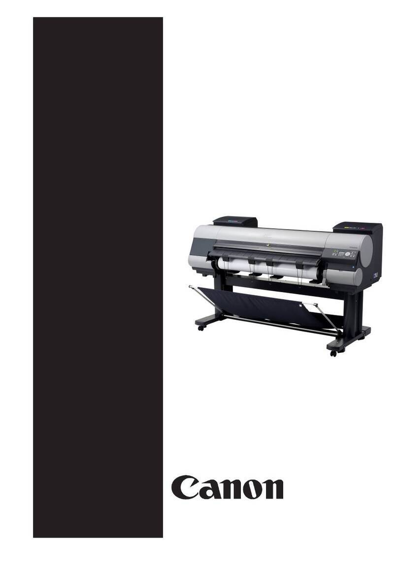
Canon imagePROGRAF IPF9000S User manual

Troubleshooting Guide
Ver. 3.0
Canon System and Support Inc.
Group Service Planning
Canon Inc.
Inkjet Quality Assurance Center
R2 - CONFIDENTIAL


Revision History (The latest revision is described in red.)
Rivision
No.
Revised Date Revised
Page
Detail
Remark
1.01
July, 2009
1.3
July, 2009
2.0
June, 2010
2.03
Apirl 4, 2014
3.0 Dec 8, 2014 2-4 Change to frame of “2.Error Code Index”
4-1
Add “Printing Nozzle Check Print” to “T01 and T-02
Interpreting Nozzle Check Patterns” and change
layout.

Conents
Chapter 1 Using This Guide................................................................................................ 1-1
1. Using This Guide ......................................................................................................................................... 1-1
2. Model Groups .............................................................................................................................................. 1-2
Chapter 2 Trouble Database ................................................................................................2-1
1. Index of Symptoms and Imaging Failures ................................................................................................... 2-1
A. Imaging Failures ...................................................................................................................................... 2-2
B. Operational Failures ................................................................................................................................ 2-2
C. Functional Failures .................................................................................................................................. 2-2
D. Cutting Failures ....................................................................................................................................... 2-2
E. Unusual Noises ........................................................................................................................................ 2-2
F. Application-Dependent ............................................................................................................................. 2-2
2. Error Code Index ......................................................................................................................................... 2-4
Chapter 3 More Sophisticated Fault Isolation Tasks .........................................................3-1
1. 【2F13】AD converter external trigger output error (HW-1 fault) ............................................................... 3-1
2. 【2F1F】Purge sensor error .......................................................................................................................... 3-2
3. 【2F26】Carriage operation disabled ........................................................................................................... 3-4
4. 【2F2F】Non-ejection detection error, 【2F30】Non-ejection detecting position adjustment error ................ 3-6
5. 【200C】Roll paper leading edge detection error, 【200D】Cut sheet leading edge detection error ............ 3-8
6. 【2010】Skew detection error, 【2017】Paper right side detection error, 【2018】Paper left side detection
error, 【2405】Borderless printing disabled ................................................................................................ 3-12
7. 【2E27】Paper jam while feeding, ejecting or printing on paper (Jam 1) ................................................... 3-14
8. 【2E25】Paper jam while feeding, ejecting or printing on paper (Jam 2) ................................................... 3-15
9. 【2E24】Faulty roll paper unit, 【2E0E】Roll paper unit not available ......................................................... 3-16
10. 【2015】Cutting failure (Cannot cut sheet) ............................................................................................... 3-17
11. 【2F24】Cutter shift timeout error ............................................................................................................. 3-18
12. Cutting failures without error indications ................................................................................................. 3-20
13. 【403E】,【403F】Printhead abnormal temperature rises .......................................................................... 3-21
14. 【4027】Carriage lifting error .................................................................................................................... 3-22
15. Imaging Failures ①Soiled print side, ink dropping, soiled reverse side, black/white dots, roller marks
.................................................................................................................................................................... 3-24
16. Imaging Failures ②Lines, streaks and bands ...................................................................................... 3-26
17. Imaging Failures ③Blurred, ghost, spread, shaken or undersharp images ........................................ 3-30
18. Imaging Failures ④Line and character errors ...................................................................................... 3-32
19. Imaging Failures ⑤Defective toning and color misregistration ............................................................ 3-34
20. Imaging Failures ⑥Missing lines or images ......................................................................................... 3-36
21. Imaging Failures ⑦Printing in a size different from the specification ................................................... 3-38
22. Imaging Failures ⑧No printing ............................................................................................................. 3-39
23. Operational Failures ①PosterArtist won’t launch ................................................................................. 3-40
24. Operational Failures ②The main unit won’t start or the power turns off automatically (without an
error occurring) .......................................................................................................................................... 3-41
25. Operational Failures ③Cannot install ................................................................................................... 3-42
Chapter 4 Fault Isolation Tool Collection.............................................................................4-1
T01 Interpreting Nozzle Check Patterns ......................................................................................................... 4-1
T02 Nozzle Check Print Fault Isolation Tool ................................................................................................... 4-5
T03 Carriage Encoder Fault Isolation Tool.......................................................................................................4-11
T04 Information required to request investigation ..........................................................................................4-11
T05 Collecting a PRN File (Windows only) ................................................................................................... 4-12

T06 Collecting PC Detailed Information ........................................................................................................ 4-13
T07 Collecting Printer Driver Settings ........................................................................................................... 4-15
T08 Driver Function Description .................................................................................................................... 4-17
T09 Collecting Status Information ................................................................................................................. 4-18
T10 Collecting Screen Shots ......................................................................................................................... 4-19
T11 Ink Supply System Fault Isolation Tool ................................................................................................... 4-20
T12 Purge Unit Fault Isolation Tool ............................................................................................................... 4-23
T13 Carriage encoder installation fault isolation tool .................................................................................... 4-24
T14 How to unlock the carriage (without having to remove the cover) ......................................................... 4-24
T15 Recommended head adjustment procedure .......................................................................................... 4-25
T16 Recommended band adjustment procedure .......................................................................................... 4-25
T17 Electrical ejection fault isolation tool ...................................................................................................... 4-26
T18 Flat Cable Fault Isolation Tool ................................................................................................................ 4-30
T19 Special Mode for Servicing ..................................................................................................................... 4-32
T20 Cleaning operation ................................................................................................................................. 4-37
Chapter 5 Miscellaneous Information .................................................................................5-1
1. How to interpret Print Inf .............................................................................................................................. 5-1
2. Upgrading Firmware ...................................................................................................................................5-11
(1) Upgrading method .................................................................................................................................5-11
(2) Upgrading using FUT (Firmware Update Tool) ......................................................................................5-11
(3) Upgrading using L Printer Service Tool .................................................................................................5-11
(4) Relationship with MCT (imagePROGRAF Media Configuration Tool) ...................................................5-11
3. Description of L Printer Service Tool, and How to Use It .......................................................................... 5-12
(1) What you can do with this tool .............................................................................................................. 5-12
(2) Installation procedure ........................................................................................................................... 5-12
(3) Viewing and saving Print Inf and status information (Download to the PC as data) ............................ 5-13
(4) Upgrading (downgrading) firmware ...................................................................................................... 5-13
4. Notes on Replacing Parts .......................................................................................................................... 5-14
(1) Replacing PCBs .................................................................................................................................... 5-14
(2) Periodically replaced parts (Refresh Service Kit) ................................................................................. 5-14
5. Greasing .................................................................................................................................................... 5-15
6. Replacing the Head ................................................................................................................................... 5-20
Chapter 6 Main Unit Configuration Diagrams ....................................................................6-1
1. LFP-IJ Printer Basic Configuration Diagram ............................................................................................... 6-1
2. Paper Paths by Series ................................................................................................................................. 6-3
(1) iPF5000 Series ....................................................................................................................................... 6-3
(2) iPF700 Series ......................................................................................................................................... 6-4
(3) iPF8000 Series ....................................................................................................................................... 6-5
(4) iPF800 Series ......................................................................................................................................... 6-6
(5) iPF650/750 Series .................................................................................................................................. 6-7

Chapter 1
Using This Guide


Chapter 1 Using This Guide
1. Using This Guide
STEP1: Find a relevant phenomenon from Chapter 2, “Trouble Database.”
STEP2:
Go to Chapter 3, “More Sophisticated Fault Isolation Tasks.”
From operation panel displays
From last 4 digits of error codes (panel display, Print Inf)
From imaging (user complaint) problems
From other problems (such as abnormal noise and taking too long)
From software-specific problems (e.g., Microsoft Word)
If any component
name or the like is
unknown, see
Chapter 6, “Main Unit
Configuration
Diagrams: Paper
Paths.”
STEP3:
Go to Chapter 4, “Fault Isolation Tool Collection.”
1-1

Chapter 1 Using This Guide
2. Model Groups
The iPF Series is broken down into the following groups in this Guide:
Model group
Maximum paper
width
Five-color
dye/pigment
model
Six-color
pigment model
Eight-color
pigment model
Twelve-color
pigment model
iPF8000 Series
iPF9000 Series
60 inches - - iPF9000S
iPF9400S
iPF9000
iPF9100
iPF9400
iPF9410
44 inches
(B0 extra-sized)- iPF8400SE
iPF8410SE
iPF8000S
iPF8300S
iPF8400S
iPF8410S
iPF8000
iPF8100
iPF8300
iPF8400
iPF8410
iPF800 Series
44 inches
(B0 extra-sized
)
iPF810, iPF820
iPF815, iPF825
- - -
iPF700 Series
36 inches
(A0 extra-sized
)
iPF700
iPF710, iPF720
- - -
iPF650 Series
iPF750 Series
36 inches
(A0 extra-sized)
24 inches
(
A1 extra-sized
)
iPF750, iPF755
iPF760, iPF765
iPF650, iPF655 - - -
iPF5000 Series
iPF6000 Series
24 inches
(A1 extra-sized)
17 inches
(A2 extra-sized)
- iPF6400SE
iPF6410SE
iPF6000S
iPF6300S
iPF6400S
iPF6410S
iPF6100
iPF6200
iPF6300
iPF6350
iPF6400
iPF6410
iPF6450
iPF6460
iPF5000
iPF5100
iPF500 Series
iPF600 Series
24 inches
(A1 extra-sized)
17 inches
(A2 extra-sized)
iPF600, iPF610,
iPF605
iPF500, iPF510 - - -
1-2

Chapter 2
Trouble Database


Chapter 2Indexes by Case
1. Index of Symptoms and Imaging Failures
Category
Imaging Failures ······························································A
Operational Failures ·························································B
Functional Failures ····························································C
Cutting Failures ································································D
Unusual Noises ································································E
Application-Dependent ·······················································F
A. Imaging Failures
Category
Item
Subitem
Remedial Action (tool)
A
Soiled print side
Chapter 4: Imaging Failures
①
A
Ink dropping
Chapter 4: Imaging Failures
①
A
Soiled reverse side
Chapter 4: Imaging Failures
①
A
Black dots (spur marks
)
Chapter 4: Imaging Failures
①
A
White dots (spur marks
)
Chapter 4: Imaging Failures
①
A
Roller marks
Chapter 4: Imaging Failures
①
/
②
A
Peeled ink
Chapter 4: Imaging Failures
①
A
Line, streaks and bands
Chapter 4: Imaging Failures
②
A
Blurred or undersharp images
Chapter 4: Imaging Failures
③
A Blurred or blotted images Chapter 4: Imaging Failures ③
A
Shaken or ghost images
Chapter 4: Imaging Failures
③
/
④
A
Thick or double lines or characters
Chapter 4: Imaging Failures
④
/
③
A
Defective toning
Chapter 4: Imaging Failures
⑤
A
Color misregistration
Chapter 4: Imaging Failures
⑤
A
Missing lines and images
Chapter 4: Imaging Failures
⑥
A
Printing different from settings
Chapter 4: Imaging Failures
⑦
A
No printing
Chapter 4: Imaging Failures
⑧
A Wrong length Prioritize length (specify a magnification).
Specify a magnification for the present output matter (enter a
menu description).
A Wrinkled paper
Remove the cause of skewing.
Clean the cassette pick-up roller.
A Iridescent metallic luster visible Bronze symptom (reflected illuminating light colored by
diffusion on the print surface)
A Ink won’
t dry on tracing paper or the
like
Chapter 4: Imaging Failures ③
Change the drying time setting (lengthen).
A Scratching (ink peeling) Chapter 4: Imaging Failures ③
Change the drying time setting (lengthen).
A
Poor halftoning (RIP environment)
Avoid printing in black alone (but print in multiple colors).
A
Paper undertone noticeable
Change paper.
A Uneven POP board colors noticeable Properties of the paper.
Change the print mode to an upper mode.
2-1

Chapter 2Indexes by Case
B. Operational Failures
Category
Item
Subitem
Remedial Action (tool)
B
PosterArtist won’t launch
Chapter 4: Operational Failures
①
B
The main unit won’t start
Chapter 4: Operational Failures
②
B
Power turns off automatically
Chapter 4: Operational Failures
②
B Network-connected printer, once
visible, out of sight
If “Automatic”
is selected for the IP address of the printer, assign
a fixed IP address to it.
C. Functional Failures
Category
Item
Subitem
Remedial Action (tool)
C
Freezing/slow
Restart the printer.
C
Upgrade the firmware.
C If paper has been added, initialize the Paper preferences and
update additional Paper from System Settings (user settings
will be lost).
C
No printing
Underpowered host PC
C
Check the network environment.
C
Bug in AutoCAD high-speed rendering/Ver.3.00 or later
D. Cutting Failures
Category
Item
Subitem
Remedial Action (tool)
D
Wavy cut surface
Chapter 4: Cutting failures without error indications
D Residual cutting chips on the reference
side
Chapter 4: Cutting failures without error indications
D
Normally ended without cutting
Chapter 4: Cutting failures without error indications
D Line printed at the cutting position, but
without actual cutting
Chapter 4: Cutting failures without error indications
D Line printed at the cutting position on
printing
Chapter 4: Cutting failures without error indications
D
Cut automatically
Chapter 4: Cutting failures without error indications
D
Images cut halfway
Chapter 4: Cutting failures without error indications
E. Unusual Noises
Category
Item
Subitem
Remedial Action (tool)
E
Carriage drive Rasping
After checking the idler pulley, go to 2F26.
E
Check the carriage tension unit.
E
Chattering
The tube has hit the exterior to generate unusual noises.
E Open and close the platen suction path selection valve
(normal).
E Creaky Soiled carriage rail/Clean dry (never apply oil)/replace the
rail cleaner/replace the carriage bearing.
E Broken head open/close lever
Replace the lever.
2-2

Chapter 2Indexes by Case
Category
Item
Subitem
Remedial Action (tool)
E
Head rubbing Tizzy
Check the head height setting.
E
Check for jams.
E
Check the paper type setting.
E
Cutter Clattering
Check to see if the fixed teeth are not dented.
E
If the round and fixed teeth are found dented, replace both.
E
Near the ink tank unit
Chattering
Ink is stirred in a timed operation (normal).
E Roll spool (opposite to the HP) Noise of jumping gear teeth
Replace the rubber pad in correct position.
E Paper feed/back feed LF backup roller sound
Replace with a roller-less part.
E Caterpillar mylar Mylar sheet out of position
Replace the tube unit.
E
Platen suction hole
Whistling
Clean the hole.
F. Application-Dependent
Category
Item
Subitem
Remedial Action (tool)
F
AutoCAD
Defective toning
Chapter 4: Imaging Failures
⑤
F Missing images (a part of image is
missing in printout)
Chapter 4: Imaging Failures ⑥
F
Printed in a double or half size
Chapter 4: Imaging Failures
⑦
F
No printing
Chapter 4: Imaging Failures
⑧
F
Cannot install the HDI driver
Chapter 4: Operational Failures
③
F Cannot print a size longer than
2300 mm with the HDI driver
AutoCAD2004 specification
F
Word
No magnified printing
Chapter 4: Imaging Failures
⑦
F
Excel
Narrow white lines in the print
Chapter 4: Imaging Failures
②
F Missing images (a part of image is
missing in printout)
Chapter 4: Imaging Failures ⑥
F
Illustrator
Narrow white lines in the print
Chapter 4: Imaging Failures
②
F
Blurred or undersharp images
Chapter 4: Imaging Failures
③
F
PosterArtist
Won’t launch
Chapter 4: Operational Failures
①
F WINSTAR CAD Misregistration in printing on
manually fed paper Reduce the data setting to allow in
consideration of the application
specifications/margins.
F Bundled user software CD
The installer does not launch when
the bundled user software CD is
mounted.
Chapter 4: Operational Failures ③
2-3

Chapter 2Indexes by Case
2. Error Code Index
Code
(last 4
digits)
Panel display
Explanation/Detection sequence
Remedial Action
(★: Reference fault
isolation procedure
or tool)
Large LCD Small LCD
-
Sheet printing
is selected, but
a roll is loaded.
Paper mismatch (cut sheet)
Print data having a cut sheet print
specification has been received with
rewinder use being selected.
Printing on cut
sheet is not
functional with a
rewinder in use.
-
Media Type not
compatible with
cassette.
Check Media Type.
Stop: Stop Printing
Media Check
Please Cancel
Cas Cannot Feed
Please Check
Paper mismatch (cut sheet)
Cassette pickup has been specified for
paper that does not support cassette pickup.
Check the
cassette pick-up
setting/paper
type.
-
Regular printing
is selected, but
a roll is loaded.
Press OK,
remove the roll,
and load sheets.
Paper mismatch (cut sheet)
Print data having a manual feed print
specification has been received at the
completion of roll paper pickup.
Check the
cassette pick-up
setting/paper
type.
-
Papr Type
Mismatch
PaprTyp Mismatch
Paper mismatch (type)
(1) Mismatch following the selection of any
of the following menu choices:
- [Warning Indication] has been selected for
[Paper Mismatch Detection].
- [ON] has been selected for [Paper Error
Skip].
(2) On forced printing following a mismatch
resulting from the selection of the following
menu option:
- [Pause] has been selected for [Paper
Mismatch Detection].
This is a warning
and allows
continued
printing.
-
Paper Mismatch
Paper mismatch (both type and size)
(1) Mismatch following the selection of any
of the following menu choices:
- [Warning Indication] has been selected for
[Paper Mismatch Detection].
- [ON] has been selected for [Paper Error
Skip].
(2) On forced printing following a mismatch
resulting from the selection of the following
menu option:
- [Pause] has been selected for [Paper
Mismatch Detection].
This is a warning
and allows
continued
printing.
-
Papr Size Mismatch
PaprSiz Mismatch
Paper mismatch (size)
(1) Mismatch following the selection of any
of the following menu choices:
- [Warning Indication] has been selected for
[Paper Mismatch Detection].
- [ON] has been selected for [Paper Error
Skip].
(2) On forced printing following a mismatch
resulting from the selection of the following
menu option:
- [Pause] has been selected for [Paper
Mismatch Detection].
This is a warning
and allows
continued
printing.
-
Cannot print
as specified.
Lift the release
lever and replace
paper with A4/LTR
(vertical) or larger
Paper mismatch (size)
When performing internal printing, paper
loaded is smaller than the size specified for
each print purpose.
[XXX]: appropriate paper size
Replace the
paper with
appropriate one.
2-4

Chapter 2Indexes by Case
Code
(last 4
digits)
Panel display
Explanation/Detection sequence
Remedial Action
(★: Reference fault
isolation procedure
or tool)
Large LCD Small LCD
-
Sheet printing
is selected.
Press Load/Eject
and load sheets.
Paper mismatch (cut sheet)
No cassette paper has been loaded when
data having a cut sheet specification is
received. (Paper type /size not determined)
Load cut sheet.
-
Sheet printing
is selected.
Paper mismatch (cut sheet)
No cassette paper has been loaded when
data having a cut sheet specification is
received.
(Paper type /size not determined)
Load cut sheet.
-
Paper Pos Wrong
Paper Pos Wrong
Invalid paper loading position
Paper is invalidly positioned on the platen.
Go to ★2010
(P3-12).
-
Turn on the media
take-up unit.
Printing has started with the media take-up
unit setting of [Use] and with the rewinder
switched off.
Switch on the
rewinder.
*A measure for a
third-party
rewinder that is
not connected
to the main unit.
-
Media take-up unit
ready.
Online: Print
Stop: Stop Printing
Rewinder use has been set to [Do not use]
at the start of printing when the rewinder is
active.
①Press the
[Online] button
to set the
rewinder use
setting to force
[Use] and print.
②Press the
[Stop] key to
cancel printing.
-
End of paper feed.
Cannot feed
paper more.
Feed Limit..
Forced feed limit
Paper being manually fed in the return
direction (back-feeding) has reached the
pinch roller position.
The message
clears
automatically 2
seconds later.
Check the PE
sensor (IO
mode).
-
Close Ink Tank
Cover
Ink tank cover open while printing
On a model having a subtank, the ink tank
cover opened while printing. (Printing is
allowed to continue.)
The message
clears when the
ink tank cover is
closed.
Check the sensor
(IO mode).
-
The roll feed unit
is loose. Push it
all the way in.
The roll unit has been pulled out during
standby or printing on the lower roll paper or
cut sheet A3 or less.
Close the roll unit.
-
Prepare for parts
replacement.
Call for service.
WLevel 1
Durable parts replacement due soon
Any of the parts counters has reached
warning level 1.
Check the parts
counter and
prepare the target
unit or Refresh
Service Kit.
Initialize the parts
counter for the
target unit after the
replacement.
Consumables Low
-
Parts replacement
time has passed.
Call for service.
WLevel 2
Durable parts replacement due soon
Any of the parts counters has reached
warning level 2.
Repl Consumables
2-5

Chapter 2Indexes by Case
Code
(last 4
digits)
Panel display
Explanation/Detection sequence
Remedial Action
(★: Reference fault
isolation procedure
or tool)
Large LCD Small LCD
1000
to
100C
Ink Level: Check
Ink Lvl: Chk XX
Ink tank near-empty (continued use allowed)
The remaining volume of ink is diminishing
(below the pin check level).
(XX: Target color display)
Last 2 digits of error code:
00:Bk, 01:Y, 02:M, 03:C, 04:PM, 05:PC,
06:MBk1, 07:MBk2, 08:GY, 09:PGY, 0A:R,
0B:B, 0C:G
①Replace the
tank (continued
usage
allowed).
②If the problem
persists after
the tank has
been replaced,
the remaining
ink detection
system is at
fault. (Replace
the supply unit
or check
catching wire or
connection
status of
harness.)
Not much ink is
left. Prepare to
replace the ink.
100F End of paper feed.
Cannot feed
paper any more.
End of paper feed. The limit of forced paper feeding. The media
reached to a pinchroller at feeding backfeed
media manually.
(not an error or a failure)
The message is
cleared
automatically after
displaying for
2sec.
Confirmation of
LF_PE sensor (IO
mode)
1010
Problem with
Printhead L/R
Chk printing results
CheckPrintout:LR
Head non-ejection warning (Check printout/
possible to continue printing)
See 280C for detection criteria.
①Check image
quality. (Unless
there are
problems with
the image
quality, there is
no need to
replace the
head.)
②Replace the
head.
★If the problem
persists, go to
2F2F (P3-6).
Check printed
document.
Check Printout
1012
Problem with
Printhead R
Chk printing results
CheckPrintout:R
Head R non-ejection warning (double-head
model)
(Check printout/ possible to continue printing)
See 280C for detection criteria.
1013
Problem with
Printhead L
Chk printing results
CheckPrintout:L
Head L non-ejection warning (double-head
model)
(Check printout/ possible to continue printing)
See 280C for detection criteria.
2-6

Chapter 2Indexes by Case
Code
(last 4
digits)
Panel display
Explanation/Detection sequence
Remedial Action
(★: Reference fault
isolation procedure
or tool)
Large LCD Small LCD
1015
This type of paper
is not compatible
with HP-GL/2.
GL2: Unsup. papr
HP-GL2 error: out of the scope of paper
support
[Warning Indication] or [Pause] have been
selected for [Paper Mismatch Detection].
The paper that is being fed does not support
HP-GL/2 printing; that is, a paper type that
does not have a required print mode has
been set.
When [Warning
Indication] is
selected
Replace with
appropriate paper.
When [Pause] is
selected
①Press the
[Online] button
to force printing.
Caution) Due to
use of image
process table
(LUT) defined
for HP-GL/2
compatible
paper different
from the
specified paper,
you might have
a problem in
quality of image.
②Press the [Stop]
button to cancel
printing.
GL2: Incompatible
paper type
Press Online Starts
printing
1021
Papr Type
Mismatch
MediaType Mismatch
Paper mismatch (type)
With [Warning Indication] is selected for
[Paper Mismatch Detection], the type of
loaded paper mismatches the specified type.
Or, with [Pause] is selected for [Paper
Mismatch Detection], the [Online] button was
pressed to execute forced printing.
Continued printing
is allowed.
Check driver
setting. Replace
with appropriate
paper.
1022
Papr Type
Mismatch
MediaType Mismatch
Paper mismatch (type)
With [Warning Indication] is selected for
[Paper Mismatch Detection], the type of
loaded paper mismatches the specified type.
Or, with [Pause] is selected for [Paper
Mismatch Detection], the [Online] button was
pressed to execute forced printing.
Continued printing
is allowed.
Check driver
setting. Replace
with appropriate
paper.
1030
GARO W1221
GARO W1221
(Image mode)Unknown command
A character that is located within bounds of
a group character or end parameter
character but that is not defined as a
command has been detected during Image
mode command decoding.
①Identify the
model.
②If the error has
occurred with
RIP, try with the
printer driver.
③Try in an
alternative
environment
(I/F, PC).
1031
GARO W1222
GARO W1222
(Image mode
)
Invalid parameter count (no
parameters)
A numeric field has not been identified as
being numeric during Image mode
command decoding.
2-7

Chapter 2Indexes by Case
Code
(last 4
digits)
Panel display
Explanation/Detection sequence
Remedial Action
(★: Reference fault
isolation procedure
or tool)
Large LCD Small LCD
1032
GARO W1223
GARO W1223
(Image mode)Required item missing
A character out of bounds has been
detected where a group or end parameter
character ought to exist, during Image mode
command decoding.
1034
GARO W1225
GARO W1225
(Image mode)Other warning
A character other than <ESC> has been
detected right after the image mode analysis
module entered Image mode or when the
decoding of a single command ended.
1035
GARO W1231
GARO W1231
(Setup mode)Unknown command
A command character string other than
RESET, SET, OPCMT0 and OPCMT2 has
been detected in a PJL command.
1036
GARO W1232
GARO W1232
(Setup mode)Invalid parameter count
Too many or too few parameters have been
detected during Setup mode command
decoding.
1037
GARO W1233
GARO W1233
(Setup mode) Required item missing
The exit parameter is missing in the
EnterGAROMode command and the
UniversalExitLanguage command used in
Setup mode.
1038
GARO W1234
GARO W1234
(Setup mode)Data out of bounds
A character string that is not defined as an
environmental variable has been detected.
An unknown environmental variable has
been detected.
A character string that is not defined as an
environmental variable value has been
detected.
The value of an unknown environmental
variable has been detected.
1039
GARO W1235
GARO W1235
(Setup mode) Other warning
A character string other than the @PJL
prefix has been detected while the analysis
module was idle.
103A
GARO W1226
GARO W1226
(Image mode) Image processing table error
No image processing table is being
transmitted, a required image processing
table is unavailable, or an image processing
table contains a value out of bounds.
①
Retransmit.
②Check with a
different
interface
choice.
③Try by printing
other data.
④With RIP, print
from the print
driver.
Supplement: If
this error
occurs, the print
result would
appear blank.
1040
GL2: W0501
The memory is full.
GL2: W0501
HP/GL2 error; Insufficient memory capacity
The size of drawing data exceeds the
processing capacity.
①Reduce the size
of rendering
data.
②Replace with
HP RTL data for
manipulation
with On The Fly.
1041
GL2: W0502
The parameter is
out
of range.
GL2:W0502
HP/GL2 error; invalid parameter
Data having an invalid number of types of
parameters that follow the command has
been detected.
Verify the data
and fix it.
2-8
Other manuals for imagePROGRAF IPF9000S
3
This manual suits for next models
32
Table of contents
Other Canon Plotter manuals

Canon
Canon iPF750 series User manual

Canon
Canon imagePROGRAF TM Series User manual

Canon
Canon imagePROGRAF TX-4100 Setup guide

Canon
Canon iPF710 - imagePROGRAF Color Inkjet Printer User manual

Canon
Canon imagePROGRAF TM-200 Setup guide

Canon
Canon image Prograf iPF780 Series User manual

Canon
Canon imagePROGRAF BU-03 User manual

Canon
Canon iPF825 User manual

Canon
Canon iPF800 Series User manual

Canon
Canon TZ-5300 User manual