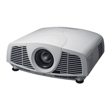
Canon WUX5800 User manual

(1/28)
LCOS Projector WUX5800/WUX6700/WUX7500
1. Main Features
<Product lineup >
●WUX 5800: WUXGA resolution , 5800 lm , lamp light source
●WUX 6700: WUXGA resolution , 6700 lm , lamp light source
●WUX 7500: WUXGA resolution , 7500 lm , lamp light source
< Common specifications to all three models >
●Integration of AISYS illumination optical processor, Chalcedony image processor, and LCOS panel system
technologies
●Support for numerous interfaces including HDMI, DisplayPort, HDBaseT, and DVI-I
●Improved video visibility
●Supports service apps (Canon Service Tool for PJ )
・iOS application is used to establish a Wi-Fi connection with the projector, and enables remote control
operations and projector status management easily.
●Built-in RTC(Real-Time Clock)
・Scheduler function that can be configured to perform actions, such as starting or shutting down the
projector at specified times.
・Improved information accessibility through log information linking
●Low-delay playback with no more than 1.0 frame of delay
●Low noise at 27 dB
●sRGB coverage 90% or higher
●Spigot lens mount
・A new single-action replaceable projection lens mount to ensure expandability for future projection lens
with new functions

(2/28)
2. Specifications
2-1. Basic specifications
1.Product classification
Item name
Image device, number
Projection lens
Projector
Reflective LCD panel (LCOS), 3 panels
Detachable
2.Image device
Number of pixels
Display size
Aspect ratio
1920×1200 (WUXGA)
0.71 type
16:10
3.Light source
Type
Power consumption
Super high pressure lamp for projectors
WUX5800: 343/300/262 W
WUX6700: 386/300/262 W
WUX7500: 430/300/262 W
** Changed with the lamp mode setting
Full power / power saver 1 / power saver 2
4.Images
Optical system
Light output
Marginal lumination ratio
Contrast ratio
Native
Lamp control “On”
Electronic zoom
Keystone correction
Dichroic mirror and PBS color separation-combination system
* When the image mode is set to presentation
* When standard type is used for the projection lens
WUX5800: 5800/5200/4500 lm
WUX6700: 6700/5200/4500 lm
WUX7500: 7500/5200/4500 lm
** Changed with the lamp mode setting
Full power / power saver 1 / power saver 2
The luminance values for modes other than Full power are
calculated and are not guaranteed as specifications
* When standard type is used for the projection lens
90%
* All white : all black
* When standard type is used for the projection lens
Not disclosed
2000:1 (The lamp light is decreased at all black display.)
Maximum 12x (for length)
Vertical direction ± 20°
Horizontal direction ± 20°

(3/28)
5.Terminals and I/O signals (1)
DVI-I
Digital PC input
Analog PC input
HDMI
Digital PC input
Digital video input
DisplayPort
Mini Dsub15
Analog PC input
Component video input
RJ-45
HDBaseT input
Network connection
USB Type A
USB data transmission
WUXGA,UXGA,WSXGA+,SXGA+,WXGA+,FWXGA,WXGA,SXGA
,XGA,SVGA,VGA
WUXGA,UXGA,WSXGA+,SXGA+,WXGA+,FWXGA,WXGA,SXGA
,XGA,SVGA,VGA
WUXGA,UXGA,WSXGA+,SXGA+,WXGA+,FWXGA,WXGA,SXGA
,XGA,SVGA,VGA
1080p,1080i,720p,576p,480p
**Audio input supported
Equivalent to the HDMI terminal
* The details of digital PC signals are different between DVI-I and
HDMI/DisplayPort.
WUXGA,UXGA,WSXGA+,SXGA+,WXGA+,FWXGA,WXGA,SXGA
,XGA,SVGA,VGA
1080p,1080i,720p,576p,576i,480p,480i
*Switched automatically between HDBaseT and general network
Image, audio, control and network (100BASE-TX)
** Equivalent to the image and audio of HDMI/DisplayPort
Network (100BASE-TX)
NMPJ screen transfer (CANON original protocol)
JPEG still image
Firmware version up
6. Terminals and I/O signals (2)
Mini jack
Mini jack
Mini jack
Dsub9
RS-232 connection
Audio input
Audio output
Wired remote connection
User command
Firmware version up

(4/28)
7.Mechanics
Lens shift
Lens mount
Adjustable feet
Dimensions
Weight
Noise level
Electric powered
Amount of lens shift
** When standard type is used for the projection lens
** When the lens shift mode is set to normal
Vertical direction +55%/-15%
Horizontal direction +10%/-10%
Spigot type
Four locations on the bottom
Extension length: 14.6 mm
Maximum angle of inclination: ±1.8°
W: 480 mm, H: 196 mm, D: 515 mm
Approx. 13 kg
WUX5800: 35/29/27 dB
WUX6700: 37/29/27 dB
WUX7500: 40/29/27 dB
** Changed with the lamp mode setting
Full power / power saver 1 / power saver 2
8.Others
Infra-red receiver
Built-in speaker
Power supply
Power consumption
Standby power
Operation environment
Storage environment
One in the front and one in the back
Monaural audio: 1 W
AC100-240 V, 50/60 Hz
WUX5800: 455/385/350 W
WUX6700: 495/390/355 W
WUX7500: 555/390/355 W
** Changed with the lamp mode setting
Full power / power saver 1 / power saver 2
1.6~0.28 W
** Changed with the network and other settings
0℃ - 40℃ , 20%RH - 85%RH
-20℃ - 60℃

(5/28)
2-2. Installation Specifications
(1) Projection specifications
These products can handle different projection conditions by changing the projection lens.
The projection specifications for using the different projection lenses are detailed in a separate document.
This document will only provide an outline.
The following figure shows the projection distances when the projection lens is changed.
** For the product names of the projection lenses, refer to the name assignment notification.
** Use this information with caution because the release period may vary depending on the projection lens
The unit of the horizontal axis is meter. The projection lens projects 100-inch images in the indicated range.
Optical zoom is possible with the top four lenses. The bottom two lenses have a fixed focal length, without
optical zoom.
Projection lens
Image [inches]
Projection distance[m]
Ultra Long Zoom
60-600
4.6-89.0
Long Zoom
40-600
1.9-48.5
Standard Zoom
40-600
1.3-29.0
Wide Zoom
40-600
0.9-19.5
Short Fixed
40-300
0.69-5.17
Ultra Wide
40-300
0.45-3.51
0
Ultra Long Zoom
Long Zoom
Standard Zoom
Wide Zoom
Short Fixed
Ultra Wide
2 4 6 8 10 12 14 16

(6/28)
(2) Adjustable feet
Four adjustable feet are provided on the bottom of the
product.
The length of these feet can be adjusted to minimize the
horizontal tilt of the image projected on the screen.
The adjustable feet are detachable, and the screw holes for
them are also used to install suspension fittings.
Rotation
Rotate the adjustable feet to adjust their lengths.
The maximum extension length of each leg is 14.6
mm.
Note that if the adjustable feet are turned beyond the
extension length, they come off.
The front-to-back angle of this product can be
adjusted in the range of ±1.8 degrees relative to the
surface that the product is placed on.
** The figure is for explanation only and different from the actual product shape.
Adjustable feet
Extension

(7/28)
(3) Lens shift system
This product has a lens shift system that can move the image position vertically and horizontally.
It is electrically driven through buttons on the projector or remote.
The lens shift range is as follows:
●Lens shift mode: Normal
Projection lens
Direction
Amount of lens shift
Lens shift ratio
Ultra Long Zoom
Long Zoom
Standard Zoom
Wide Zoom
Vertical
Horizontal
55% / -15%
10% / -10%
10.5:-0.5 / 3.5:6.5
4:6 / 6:4
Short Fixed
Vertical
Horizontal
11.3% / -11.3%
4.6% / -4.6%
6.13:3.87 / 3.87:6.13
4.54:5.46 / 5.46:4.54
Ultra Wide
Vertical
Horizontal
75% / -15%
30% / -30%
1.25:-2.5 / 3.5:6.5
8:2 / 2:8
Moving to the maximum positions in both vertical and horizontal directions will cause the guaranteed
optical performance range to be exceeded.
This product is a system that only allows the lens to be shifted within the guaranteed optical performance
range.
The range of movement (guaranteed optical performance range) is illustrated later in a figure.
●Lens shift mode: Expanded
Projection lens
Direction
Amount of lens shift
Lens shift ratio
Ultra Long Zoom
Long Zoom
Standard Zoom
Wide Zoom
Short Fixed
Ultra Wide
Vertical
Horizontal
90% / -90%
30% / -30%
14:-4 / -4:14
8:2 / 2:8
With this setting, the lens can be shifted to the maximum positions vertically and horizontally, ignoring the
guaranteed optical performance range.
** Amount of lens shift is an approximate calculated value.

(8/28)
●Area in which the image can be moved (Lens shift mode: Normal)
)
The following figure shows the area in which the image can be moved (guaranteed optical performance
range) of this product.
The light gray area excluding the four corners is the guaranteed optical performance range.
○RS-SL01ST
(
Standard Zoom Lens
)、
RS-SL02LZ
(
Long Zoom Lens
)、
RS-SL04UL
(
Ultra Long
Zoom Lens
)、
RS-SL05WZ
(
Wide Zoom
)
○RS-SL03WF
(
Short Fixed Lens
)

(9/28)
○RS-SL06W
(
Ultra Wide Lens
)
●Notes (Lens shift mode: Expanded)
Moving the image outside the guaranteed optical performance range may cause shade to appear in the
corner area of the image.
We recommend that you do not use the product in this manner but rather adjust the installation position so
that the image is within the guaranteed range.

(10/28)
2-5. Installation direction
●360°projection
This product is free to install at any of the 360 degrees in the direction of rotation shown in the figure.
In other words, the product supports projection right above or below for digital signage.
○Installation orientation that is not allowed
The product cannot be installed with the side panel facing down as shown in figure A.
Fig. A Not allowed
Fig. BAllowed
Products that use discharge lamps for their light source have limitations in how they can be installed. This is
because discharge lamps by their nature have certain orientations that they cannot be used in. Using this
product in the orientation shown in figure A can cause the lamp to malfunction.
The product must be used within the range shown in figure B.
±10°

(11/28)
2-6. Image signal
(1)Supported image signal type
This product can display the following image signals.
●DVI input
●HDMI input, DisplayPort input
Signal
Type
H freq.
[kHz]
V freq.
[Hz]
Dot clock
[MHz]
Signal
Type
H freq.
[kHz]
V freq.
[Hz]
Dot clock
[MHz]
640×480
31.469
59.940
25.175
640×480
31.469
59.940
25.175
720×480
31.469
59.940
27.000
800×600
37.879
60.317
40.000
720×576
31.250
50.000
27.000
1024×768
48.363
60.004
65.000
800×600
37.879
60.317
40.000
1280×800
49.702
59.810
83.500
1024×768
48.363
60.004
65.000
49.306
59.910
71.000
1280×720
37.500
50.000
74.250
1280×1024
63.981
60.020
108.000
45.000
60.000
74.250
1366×768
47.712
59.790
85.500
1280×800
49.702
59.810
83.500
1400×1050
64.744
59.948
101.000
49.306
59.910
71.000
65.317
59.978
121.750
1280×1024
63.981
60.020
108.000
1440×900
55.935
59.887
106.500
1366×768
47.712
59.790
85.500
55.469
59.901
88.750
1400×1050
64.744
59.948
101.000
1600×900
60.000
60.000
108.000
65.317
59.978
121.750
1600×1200
75.000
60.000
162.000
1440×900
55.935
59.887
106.500
1680×1050
64.674
59.883
119.000
55.469
59.901
88.750
65.290
59.954
146.250
1600×900
60.000
60.000
108.000
1920×1200
74.038
59.950
154.000
1600×1200
75.000
60.000
162.000
1680×1050
64.674
59.883
119.000
480p
31.469
59.940
27.000
65.290
59.954
146.250
576p
31.250
50.000
27.000
1920×1080
27.000
24.000
74.250
720p
37.500
50.000
74.250
56.250
50.000
148.500
45.000
60.000
74.250
67.500
60.000
148.500
1080i
28.125
50.000
74.250
1920×1200
74.038
59.950
154.000
33.750
60.000
74.250
1920×1080
27.000
24.000
74.25
1080p
27.000
24.000
74.250
PsF
28.125
25.000
74.25
56.250
50.000
148.500
33.750
30.000
74.25
67.500
60.000
148.500
●HDBaseT input
The same resolutions and frequencies indicated for HDM/DisplayPortI input in the above table can be
displayed.

(12/28)
●Analog PC input (1, 2)
●Component video input
Signal
Type
H freq.
[kHz]
V freq.
[Hz]
Dot clock
[MHz]
Signal
Type
H freq.
[kHz]
V freq.
[Hz]
Dot clock
[MHz]
640×480
31.469
59.940
25.175
480i
15.734
59.940
13.500
720×480
31.469
59.940
27.000
480p
31.469
59.940
27.000
720×576
31.250
50.000
27.000
576i
15.625
50.000
13.500
800×600
37.879
60.317
40.000
576p
31.250
50.000
27.000
848×480
31.020
60.000
33.750
720p
37.500
50.000
74.250
1024×768
48.363
60.004
65.000
45.000
60.000
74.250
1280×768
47.776
59.870
79.500
1080i
28.125
50.000
74.250
47.396
59.995
68.250
33.750
60.000
74.250
1280×800
49.702
59.810
83.500
1080p
56.250
50.000
148.500
49.306
59.910
71.000
67.500
60.000
148.500
1280×960
60.000
60.000
108.000
1080PsF
27.000
24.000
74.25
1280×1024
63.981
60.020
108.000
28.125
25.000
74.25
1366×768
47.712
59.790
85.500
33.750
30.000
74.25
1400×1050
64.744
59.948
101.000
65.317
59.978
121.750
1440×900
55.935
59.887
106.500
55.469
59.901
88.750
1600×900
60.000
60.000
108.000
1600×1200
75.000
60.000
162.000
1680×1050
64.674
59.883
119.000
65.290
59.954
146.250
1920×1080
56.250
50.000
148.500
67.500
60.000
148.500
1920×1200
74.038
59.950
154.000
**IfthedotclockoftheanalogPCsignalishigherthan162MHz,imagewillnotbeprojected
properly.

(13/28)
●USB image input (for still images only)
When a USB memory containing image data is inserted to the USB terminal, the unit can project the
image data as an image.
Image data other than JPEG format cannot be used, and the maximum number of pixel for a picture is
10912x8640.
The unit supports only the most commonly-used format, and other formats are not supported, as shown
below:
Support
Format
Yes
Baseline DCT
No
Extended Sequential DCT
No
Progressive DCT
No
Lossless DPCM Spatial
** Digital zoom cannot be controlled on the screen for selecting the picture.
To set the slide show view of the USB image input, use the image setup menu.
To display the image of the USB image input, use the USB file browser.
●NMPJ and network image input (for still images only)
Network multi projection (NMPJ) is a function that enables the projector to receive computer screen
information over a network and project it.
This function can be used by installing the NMPJ program in the computer.
・
Obtaining NMPJ
The program is provided for free.
The method to obtain the program varies depending on the country or region, but it is mainly
downloaded from the service webpage.
・
NMPJ operation
When NMPJ is executed on a computer, the screen information is sent as data consisting of
consecutive still images to the projector over a network using Canon’s original protocol.
The resolution of the still image data is converted to match the number of pixels of the projector’s
image device (LCOS) before the data is output.
・
Image quality setting of NMPJ
Select whether to prioritize image quality or frame rate.
High
Image quality is prioritized by reducing the frame rate.
The image is sent without compression (by maintaining the image quality).
Middle
A standard setting in which a balance between image quality and frame rate
is taken into account.
Low
Frame rate is prioritized by reducing the image quality.
Use this setting when you want to reduce the network bandwidth being used.
File type
JPEG
Format
Baseline DCT
Maximum pixels
10912x8640

(14/28)
・
Modes of NMPJ
Four modes are available. Each mode is different in the number of computers and projectors that can
be connected and the functions that can be used.
Mode
PC
PJ
Direct
1
1
Meeting
10
6
Classroom
10
6
Broadcast
1
12
・
Vers ion of NM PJ
Because there are different versions, check the NMPJ manual for compatibility issues.
●Precautions when inputting analog PC signals.
If inputting analog PC signals, it is necessary to take the following precautions.
!This product does not support image signals with a dot clock of over 162MHz due to hardware
restrictions.
"Normally, image output equipment, such as computers, automatically read the EDID information from
the projector, and output image signals that can be displayed by the projector.
#However, depending on the cable that is used, there may be cases where conduction lines for
communicating EDID information are not installed in the cable.
The following is the pin layout for a Dsub15 connector.
A cable with conduction lines for Nos. 9, 12, and 15 is necessary.
Unless there are conductions lines for these pins, the image output equipment will not be able to obtain
EDID information from the projector, and will output image signals that cannot be displayed by the
projector.
$Even if a 5BNC cable is used, EDID information is not communicated, and settings must be specified on
the output equipment side so that image signals that can be displayed by this product are output.

(15/28)
(
2
)
Internal functions
●HDCP
This product is an HDCP compliant image device.
The digital image signals for HDCP contents that are encrypted and sent from digital devices connected
to the HDMI terminal, DisplayPort terminal and DVI terminal can be displayed.
It can also be displayed in image signals transmitted through HDBaseT.
・
The product
’
s HDCP version
The version is 1.4 for HDMI and DVI and 1.3 for DisplayPort.
HDBaseT is supported up to version 1.4.
●Frame lock function
Depending on the input signal’s frequency, commonly-used display devices may not be able to
synchronize the input signal’s frame with LCD’s frame, thereby showing a mixture of successive 2
frames.
The following illustrates how this mixture of frames (image shift) occurs. Numbers ①to ③indicates
the order in which these images appeared.
In this example, a composite image ②appeared when an object moved from right to left, which is a
combination of the frames before and after the movement.
This function synchronizes the LCD’s frame with that of input signal to prevent this kind of frame
mixture, and it is effective for input signals of 23 to 31 Hz and 47 to 62 Hz.
For frequencies other than these ranges, a different process takes effect in place of Frame Lock
(synchronization) to ensure that a single frame appears in the entire LCD. Therefore, composite image
like ②would not appear even in those cases.
! " #

(16/28)
2-7. States of this product
(
1
)
States
The product states can be categorized as follows:
State (*1)
Outline
No Power
No power is being supplied from outside.
The projector does not operate at all.
Off (Standby)
Power is being supplied from outside. However, the circuit is only partially
live and the projector itself is not active.
Depending on the Network function setting, this status can be categorized
into 3 modes.
Projection (On)
A status where the projector is used normally.
Power is being supplied to the entire circuit.
The lamp is lit, and image is projected.
Lamp Off
Power is supplied to the entire circuit except panel circuit.
The lamp is unlit and the cooling fan is operating.
Some action changes the projector to the projection state. However, the
lamp on time is the same as actual activation.
Error
Power is being from outside but the projector cannot be activated.
To use the projector, action should be taken according to the contents of the
error type.
Pre-warning
High temperature
If the temperature becomes almost abnormal, the projector displays the
warning of high temperature.
.This state is cleared when the temperature goes down.
Pre-warning
Lamp replacement
If the lamp replacement conditions are almost satisfied, the projector
displays the warning of the lamp replacement.
This state is cleared when the lamp counter for replacement is reset.
(
2
)
Type of Error
Each error state is defined as below.
Error name
Outline
Tem pe ra tur e
abnormality
・The internal temperature is abnormally high.
・The outside air temperature is higher than specified.
・Malfunction of thermal sensor
Faulty lamp
・The lamp is out of life.
・The lamp drive circuit is faulty.
Faulty lamp cover
・The lamp cover is not closed.
Faulty air filter unit
・No air filter is attached.
Faulty cooling fan
・The cooling fan does not operate normally.
Faulty power supply
・The supply voltage is abnormal.
・Other abnormal is occurred.
Faulty lens
・The lens unit is not connected correctly.
** Each error state may be caused by a fault other than the above.

(17/28)
2-8. HDBaseT specificqation
This product’s HDBaseT supports transmission of image signals and network data.
In addition, as a general standard of HDBaseT, these can be transmitted simultaneously.
Many of the transmitters sold in the market are equipped with HDMI input terminals and network input
terminals.
(
1
)
Outline
An HDBaseT connection is typically achieved in the following form.
●Image signals (When connection
①
uses an HDMI cable)
Output device Transmitter Receiver Display device
%&'()*+,-(./,0+1(/.(+221/-3(456*(+0(678278(3-9/:-(86(+(85+0.*/88-5;(
%<'(=>-(85+0.*/88-5(:609-58.(8>-(/*+,-(./,0+1(/086(?@A+.-=(+03(678278.(/8;(
%B'(C(5-:-/9-5(5-:-/9-.(8>-(?@A+.-=(./,0+1D(:609-58.(/8(/086(?@E)D(+03(678278.(/8;(
%F'(C(3/.21+G(3-9/:-(3/.21+G.(8>-(?@E)(./,0+1;
●Network communication (When connection
①
uses a network cable)
Network Transmitter Receiver Display device
%&'(H-8I65J(3+8+(/.(+221/-3(456*(8>-(0-8I65J(%K&'(86(+(85+0.*/88-5;(
%<'(=>-(85+0.*/88-5(:609-58.(8>-(0-8I65J(3+8+(/086(?@A+.-=(+03(678278.(/8;(
%B'(C(5-:-/9-5(5-:-/9-.(8>-(?@A+.-=(./,0+1D(:609-58.(/8(/086(0-8I65J(3+8+D(+03(678278.(/8;(
%F'(L/J-I/.-D(0-8I65J(3+8+(456*(8>-(3/.21+G(3-9/:-(/.(85+0.*/88-3(86(8>-(678278(3-9/:-(8>567,>(+0(6226./8-(
2+8>;
*1: Use in a secure network environment.
One of the features of this product is the built-in receiver. Therefore, there is no need to have a separate
receiver.
●Compatibility with transmitters
If the compatibility between this product and the HDBaseT transmitter is not sufficiently ensured, use the
product with the standby power set to “Normal”.
Network cable
①
②
③
Network cable
①
②
③

(18/28)
(
2
)
Cables and Transmission Distance
HDBaseT connections may be subject to transmission distance limitations depending on the type of network
cables and transmitters used.
Below is an actual example of what happened when a certain transmitter was used.
Band width
(example of
signal)
1.65Gbps or more
(1080p/60 @12bit)
Under 1.65Gbps
(1080p/60@8bit,1080p/24@12bit)
Cable type
CAT5e
CAT6/CAT7
Cable type
CAT5e
Transmitting
distance
70m
100m
Transmitting
distance
70m
As shown here, adequate transmission distance for handling signals with large amount of data may not be
attainable depending on the combination of the equipment and cable used. We recommend that shielded cables
be used.
(
3
)
Image Signal Quality
Because of the structural nature of the network cable, an HDBaseT signal is transmitted in parallel over four
physically separated transmission lines.
Each transmission line has a stability index value [dB]. This product detects the four values and calculates the
total.
Based on this value, the product judges the quality as follows.
Index
Display
(color)
Judgment
100-60
Green
Use recommended
59-40
Yellow
Use not recommended
39-0
Red
Not usable
(
4
)
Network via HDBaseT
There is essentially no difference in the communication quality as compared to a normal network.
NMPJ can be used in the same manner.
(
5
)
Settings and stand-by power consumption
The standby power varies depending on the settings of serial communication, standby power setting and
network settings as follows:
Wired network
Standby power setting
Serial communication
Standby power
On
Normal
Service port
(Not disclosed)
HDBaseT
(Not disclosed)
Low power
Service port
1.6 W
HDBaseT
1.6 W
Off
-
Service port
0.28 W
HDBaseT
1.5 W
** When wireless network is set to “On”, the standby power is set to “Normal”.

(19/28)
2-9. Wireless specification
(
1
)
Main specification
Transmission
standards
IEEE 802.11b
IEEE 802.11g
IEEE 802.11n
Transmission
distance
About 25 m
When no electric wave interference from the perimeter and when clear viewing to
the access point
Wi-Fi certification
Acquired
WPS
Support: Push button method (PBC), PIN code method (PIN)
Encryption
Open
WEP
WPA-PSK TKIP
WPA-PSK AES
WPA2-PSK TKIP
WPA2-PSK AES
Connection mode
Infrastructure mode
PjAP mode
(
2
)
Connection modes and Functions
Mode
Infrastructure
PjAP
Conection method
WPS (PBC, PIN)/ manual
Manual
Usable
NMPJ
User command
Control with the browser
Mail
NMPJ
User command
Control with the browser
Not usable
SNMP
PJLink / AMX / Crestron RoomView
Firmware update
Mail
SNMP
PJLink/AMX/Crestron RoomView
Firmware update
(
3
)
Auto Search
When wireless communication is already configured, this product operates in the following manner
depending on the connection mode.
Mode
Infrastructure
PjAP
Working (*1)
Connected with the last connection
destination and earlier destinations (*2)
The product starts operating as an
access point according to the set profile
(SSID and the like).
*1: (1) When the projector is started with the wireless network function set to “On”.
(2) When the wireless network function is set to “on” in the projector operating.
*2: This document omits the details of the search scope and procedure.

(20/28)
3. Accessories
Main Supplied
Accessories
Remote Control
RS-RC07
Power supply: DC 3.0V (with two AAA battery)
Communication range: approx. 8 m within ±25
degrees of the receiver
Power code
Connects the unit to a power source.
Computer cable
(only for J destination)
mini Dsub15-mini Dsub15
This is used for connection with computer.
This transmits analog PC signals.
Optional Parts
Ceiling Attachment
RS-CL15 (*1)
This is used for ceiling mount.
Ceiling Attachment Arm
RS-CL17 (*2)
This is used for ceiling mount.
Ceiling Pipe 400-600mm
RS-CL08
The RS-CL08 is used in combination with the RS-CL15
to suspend the projector at a distance below the ceiling.
Ceiling Pipe 600-1000mm
RS-CL09
The RS-CL09 is used in combination with the RS-CL15
to suspend the projector at a distance below the ceiling.
Remote Control
RS-RC07
Same as the supplied remote.
Remote Control
RS-RC05
Power supply: DC 3.0V (with two AA battery)
Communication range: approx. 8 m within ±25
degrees of the receiver
Allows for wireline connection (*3)
Replacement
Parts
Lamp Assembly
RS―LP12
Super High Pressure Lamp for projectors
Recommended lamp replacement time (*4)
Replacement air filter
RS-FL05
This filter is installed at the air intake to prevent dust
from entering.
*1: Do not attach a difference model’s attachment. The size and the weight of a product are different from other modes.
Consult a building professional before attempting to mount the projector to a ceiling.
*2: RS-CL15 and RS-CL17 are used together to mount this projector on a ceiling.
*3: Uses a commercially available audio cable (3.5Фstereo mini-plug) for cable connection.
This manual suits for next models
2
Table of contents
Other Canon Projector manuals

Canon
Canon WUX6000 User manual

Canon
Canon LV-S2 User manual

Canon
Canon LV-5200 User manual

Canon
Canon LX-MW500 User manual

Canon
Canon LV-CL15 User manual

Canon
Canon LX-MU800Z User manual

Canon
Canon 2502C016 User manual

Canon
Canon REALiS SX7 Mark II D User manual

Canon
Canon LV-WX300UST User manual
Canon
Canon LV-7355J User manual
Canon
Canon 2105B002AA User manual

Canon
Canon WUX500ST User manual

Canon
Canon LV-7380 User manual

Canon
Canon LV-7240 User manual

Canon
Canon LX-MU700 User manual

Canon
Canon LV-7290 User manual

Canon
Canon WUX10 - REALiS WUXGA LCOS Projector User manual

Canon
Canon LV-7545 User manual

Canon
Canon LV-7250 Installation instructions

Canon
Canon LV-X310ST User manual