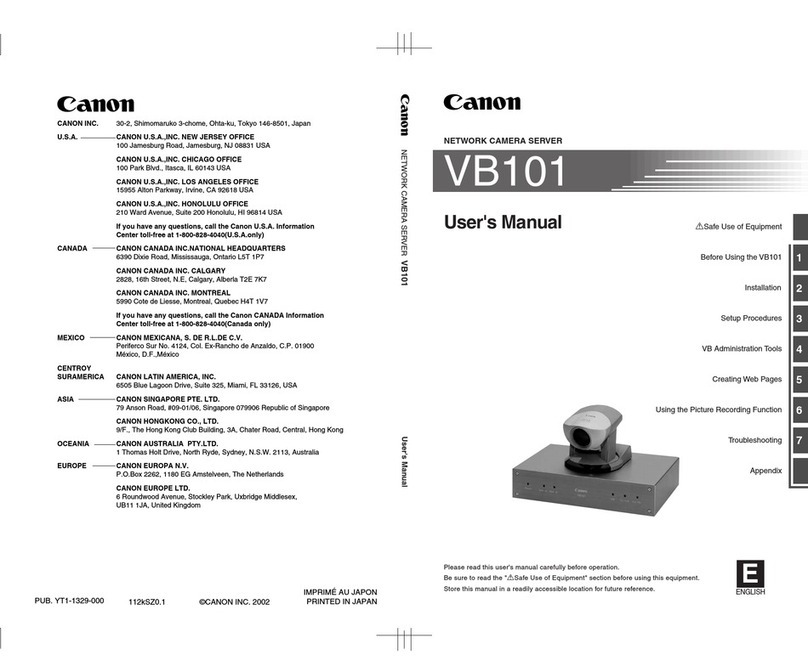
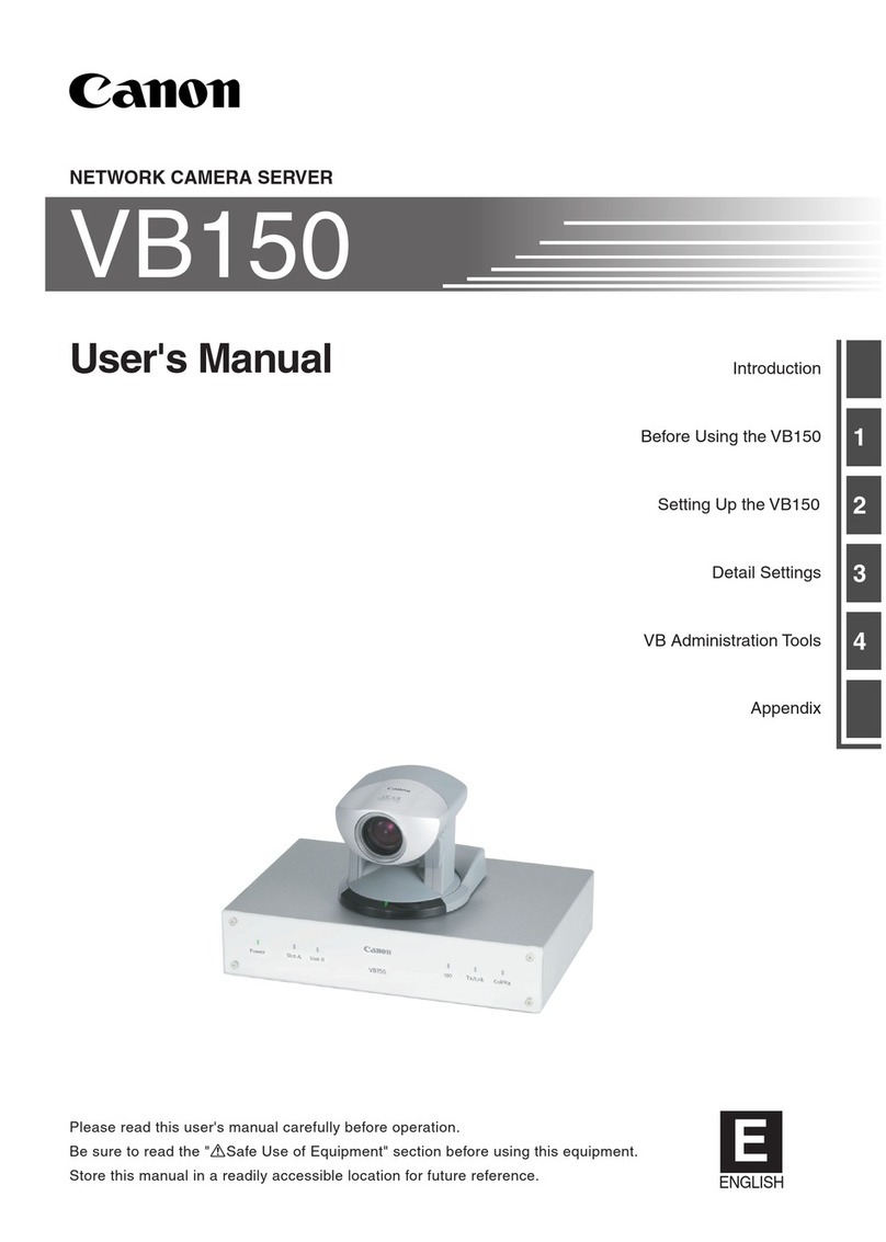
Canon VB101 User manual

1
2
3
4
5
6
VB101
aSafe Use of Equipment
Before Using the VB101
Installation
Setup Procedures
Troubleshooting
Appendix
Using the Picture Recording Function
Creating Web Pages
NETWORK CAMERA SERVER
User's Manual
Please read this user's manual carefully before opration.
Be sure to read the "aSafe Use of Equipment" section before using this equipment.
Store this manual in a readily accessible location for future reference. E
ENGLISH

Safe Use of Equipment
a
2 3
Introduction
Thank you for purchasing the Canon Network Camera Server VB101 (referred to hereafter as the
system).
This manual describes how to set up and use the server. Read this manual carefully before using
the server to ensure effective operation. In particular make sure that you read the "aSafe Use of
Equipment" in this manual, as well as the CD-ROM Readme file.
Exclusion of Liability
If the Product is connected to a recording device (for example a VCR), Canon Inc. accepts no
responsibility whatsoever for any financial losses that may be incurred as a result of the loss of
recorded information or images, regardless of the internal or external cause of the loss.
Copyright Information
Video or still images recorded using your VB101 cannot be used in ways that infringe copyright
laws or without the consent of the owner, unless intended for personal use only.
Notes
1. The unauthorized transfer of all or any part of the contents of this Manual is forbidden.
2. The contents of this Manual are subject to change without notice.
3. Every effort has been made to ensure that this Manual is flawless. However, if you find any
oversights, please let us know.
4. Item 3. notwithstanding, Canon accepts no responsibility for any effects resulting from the use of
this Manual.
Trademark Notices
●Canon and Canon logo are registered trademark of Canon Inc.
●Microsoft and Windows are registered trademarks of Microsoft Corporation in the United States
and other countries.
●Windows is legally recognized as Microsoft Windows Operating System.
●Other brand or product names in this manual may be trademarks or registered trademarks of
their respective companies.
aSafe Use of Equipment
Anexclamationpoint,withinatriangle,isintendedtoalerttheusertothepresenceofimportantoperating
and maintenance (servicing) instructions in the literature accompanying the equipment.
2aImportant Operational Instructions
1aImportant Warnings
aCAUTION:
TO REDUCE THE RISK OF ELECTRIC SHOCK, DO NOT REMOVE COVER (OR BACK).
NO USER-SERVICEABLE PARTS INSIDE. REFER SERVICING TO QUALIFIED
SERVICE PERSONNEL.
The serial number of this equipment may be found on the back of the camera
head. No others have the same serial number as yours.
You should record the number and other vital information here and retain this
book as a permanent record of your purchase to aid identification in case of theft.
Date of Purchase
Dealer Purchased from
Dealer Address
Dealer Phone No.
Model No. VB101
Serial No.
aWARNING:
TO REDUCE THE RISK OF ELECTRIC SHOCK, DO NOT EXPOSE THIS EQUIPMENT
TO RAIN OR MOISTURE.
aCAUTION:
TO REDUCE THE RISK OF ELECTRIC SHOCK AND TO REDUCE ANNOYING
INTERFERENCE, USE THE RECOMMENDED ACCESSORIES ONLY.
FDA regulation
This communication camera has not been evaluated by the Food and Drug
Administration (FDA) for use as a medical device. When incorporated into a
system with medical applications, FDA regulations may apply. Therefore,
please consult your legal advisor to determine whether FDA regulations apply.
© Copyright 2000 CANON INC.
ALL RIGHTS RESERVED

Safe Use of Equipment
a
4 5
FCC NOTICE
Network Camera Server VB101 (D78-0138)
This device complies with Part 15 of the FCC Rules. Operation is subject to
the following two conditions: (1) This device may not cause harmful
interference, and (2) this device must accept any interference received,
including interference that may cause undesired operation.
Note: This equipment has been tested and found to comply with the limits for
a Class B digital device, pursuant to Part 15 of the FCC Rules. These limits
are designed to provide reasonable protection against harmful interference in
aresidential installation. Thisequipment generates, usesandcan radiate radio
frequency energy and, if not installed and used in accordance with the
instructions, may cause harmful interference to radio communications.
However, there is no guarantee that interference will not occur in a particular
installation. If this equipment does cause harmful interference to radio or
television reception, which can be determined by turning the equipment off
and on, the user is encouraged to try to correct the interference by one or
more of the following measures:
- Reorient or relocate the receiving antenna.
- Increase the separation between the equipment and receiver.
- Connect the equipment into an outlet on a circuit different from that to which
the receiver is connected.
- Consult the dealer or an experienced radio/TV technician for help.
Use of shielded cable is required to comply with class B limits in Subpart B of
Part 15 of FCC Rules.
Do not make any changes or modifications to the equipment unless otherwise
specified in the manual. If such changes or modifications should be made,
you could be required to stop operation of the equipment.
Canon U.S.A. Inc.
One Canon Plaza, Lake Success, NY 11042, U.S.A.
Tel No. (516) 328-5600
IC NOTICE
This product does not exceed the Class B limits for radio noise emissions
from digital apparatus as set out in the Interference-causing equipment
standard entitled ‘Digital Apparatus’, ICES-003 of the Industry Canada.
NOTIFICATION IC
Cet appareil numériquw respecte les limites de bruits radioélectriques
applicables aux appareils numériques de Classe B prescrites dans la norma
sur le matériel brouilleur: “Appareils Numériques”, NMB-003 édictées par
I’lndustrie Canada.
In these safety instructions, the word
“equipment” refers to the Canon Network
Camera Server VB101 and all its
accessories.
1. Read Instructions - All the safety and
operating instructions should be read
before the equipment is operated.
2. Retain Instructions - The safety and
operatinginstructionshouldberetained
for future reference.
3. Heed Warnings - All warnings on the
equipment and in the operating
instructions should be adhered to.
4. Follow Instructions - All operating and
maintenance instructions should be
followed.
5. Cleaning - Unplug this equipment from
the wall outlet before cleaning.
Wipe the equipment with a clean soft
cloth.Ifnecessary,puta cloth in diluted
neutraldetergent andwring itwellbefore
wiping the equipment with it. Finally,
clean the equipment with a clean dry
cloth. Do not use benzene, thinner or
other volatile liquids or pesticides as
they may damage the product’s finish.
Whenusing chemically-treatedcleaning
cloths, observe those precautions
accordingly.
6. Accessories - Do not use accessories
not recommended in this manual as
they may be hazardous. Always use
specified connection cables. Connect
devices correctly.
7. WaterandMoisture-Hazardofelectric
shock - Do not use the equipment near
wateror in rainy/moistsituations. Do not
put a heater near this equipment.
8. Placing or Moving - Do not place on an
unstable cart, stand, tripod, bracket or
table. The equipment may fall, causing
serious injury to a child or adult, and
serious damage to the equipment. An
equipment and cart
combination should
be moved with care.
Quick stops, excessive force, and
uneven surfaces may cause the
equipment and cart combination to
overturn.
9. Power Sources - The PA-V16 AC
adapter should be operated only from
the type of power source indicated on
the marking label. If you are not sure of
the type of power supply to your home,
consult your equipment dealer or local
power company.
10. Polarization - The PA-V16 AC adapter
is equipped with a polarized 2-prong
plug(a plughavingone bladewider than
the other).
The 2-prong polarized plug will fit into
thepower outlet only one way. This is a
safetyfeature. If youare unable toinsert
theplug fully intothe outlet, tryreversing
theplug. Iftheplug still failsto fit, contact
yourelectrician to replaceyourobsolete
outlet.Do not defeat thesafetypurpose
of the polarized plug.
11. Power Cord Protection - Power cords
should be routed so that they are not
likely to be walked on or pinched by
itemsplaced upon or againstthem.Pay
particularattention toplugsand thepoint
fromwhich thecordsexit theequipment.
12. Outdoor Antenna Grounding - If an
outside antenna is connected to the
equipment, be sure the antenna is
grounded so as to provide some
protection against voltage surges and
built-up static charges. Section 810 of
the National Electrical Code, ANSI/
NFPANo.70-1984, providesinformation
with respect to proper grounding of the
mast and supporting structure,
grounding of the lead-in wire to an
antenna discharge unit, size of
grounding conductors, location of
antenna antenna discharge unit,
connection to
grounding electrodes,
and requirements for the grounding
electrode. See figure 1.
3aIMPORTANT SAFETY INSTRUCTIONS
a
Safe Use of Equipment
a
Safe Use of Equipment
Dieses Produkt ist zum Gebrauch im Wohnbereich, Geschäfts- und
Gewerbebereich sowie in Kleinbetrieben vorgesehen.

Safe Use of Equipment
a
6 7
fig-1
EXAMPLE OF ANTENNA GROUNDING AS
PER NATIONAL ELECTRICAL CODE
ANTENNA
LEAD IN WIRE
ANTENNA
DISCHARGE
UNIT (NEC
SECTION 810-20)
GROUNDING
CONDUCTORS
(NEC SECTION
810-21)
GROUNDING CLAMPS
POWER SERVICE
GROUNDING ELECTRODE
SYSTEM
(NEC ART 250.PART H)
NEC — NATIONAL ELECTRIC CODE
ELECTRIC
SERVICE
EQUIPMENT
GROUNDING
CLAMP
13. Lightning - For added protection of this
equipment during a lightning storm, or
when it is left unattended and unused
for long periods of time, disconnect it
fromthewalloutletanddisconnectthe
antenna. This will prevent damage to
the equipment due to lightning and
power-line surges.
14. Power Lines - An outside antenna
system should not be located in the
vicinity of overhead power lines or
other electric light or power circuits,
or where it can fall into such power
lines or circuits. When installing an
outsideantennasystem,extremecare
should be taken to keep from touching
such power lines or circuits as contact
with them might be fatal.
15. Overloading - Do not overload wall
outletsandextension cords as this can
result in a risk of fire or electric shock.
16. Object and Liquid Entry - Never push
objects of any kind into this equipment
through openings as they may touch
dangerous voltage points or short out
parts that could result in a fire or
electric shock. Be careful not to spill
liquid of any kind onto the equipment.
17. Servicing - Do not attempt to service
this equipment yourself as opening or
removing covers may expose you to
dangerous voltage or other hazards.
Refer all servicing to qualified
personnel.
18.
DamageRequiring Service -Disconnect
this equipment from the wall outlet and
allpower sourcesincluding batteries,and
refer servicing to qualified service
personnelunder thefollowingconditions.
a. When the power-supply cord or plug
is damaged.
b. If any liquid has been spilled onto, or
objects have fallen into, the
equipment.
c. If the equipment has been exposed
to rain or water.
d. If the equipment does not operate
normally even if you follow the
operating instructions. Adjust only
thosecontrols thatarecovered by the
operation instructions. Improper
adjustment of other controls may
resultin damageandwill oftenrequire
extensive work by a qualified
technician to restore the equipment
to its normal operation.
e. If the equipment has been dropped
or the cabinet has been damaged.
f. When the equipment exhibits a
distinct change in performance. This
indicates a need for service.
19. Replacement Parts- Whenreplacement
parts are required, be sure the service
technician has used replacement parts
thatare specified byCanonor that have
the same characteristics as the original
part. Unauthorized substitutions may
result in fire, electric shock or other
hazards.
20. Safety Check - Upon completion of any
serviceor repairs tothisequipment, ask
theservicetechnician to perform safety
checksto determine that theequipment
is in safe operating order.
21. Do not install the equipment in the
following locations as this can cause a
fire or electric shock:
- Hot locations
- Close to a fire
- Very humid or dusty locations
- Locations exposed to direct sunlight
- Locations exposed to salt spray
- Closetoflammable solvents(alcohol,
thinners, etc.)
22. When any of the following occurs,
immediatelyswitch OFF theequipment,
unplug it from the main power supply
and contact your nearest Canon
supplier. Do not continue to use the
equipment as this can cause a fire or
electric shock.
- The equipment emits any smoke,
heat, abnormal noise, or unusual
odor.
- A metal object falls into the
equipment.
- The equipment is damaged in some
way.
23. Please observe the following when
using the equipment. Failure to do so
can result in a fire or electric shock.
- Do not use flammable sprays near
the equipment.
- Do not subject the equipment to
strong impacts.
24. Please observe the following when
handling the batteries. Failure to do so
can result in the batteries bursting or
emitting heat, sparks or corrosive fluid.
- Do not throw the batteries into a fire,
and do not heat, short-circuit or
attemptto disassemble the batteries.
- Do not attempt to recharge the
batteries.
- Donotusebatteries other thanthose
specified for use with the equipment.
25. Please observe the following when
handling the batteries. Failure to do so
may result in the batteries bursting or
emitting heat, sparks or corrosive fluid.
- When the batteries are used up, or
when the equipment will not be used
for an extended period, remove the
batteries.
- Whenreplacingthebatteries, always
replaceboth batteries,anddo notuse
different types of batteries together.
- Ensure that the + and - terminals are
correctly positioned when you load
the batteries.
- Ifanysoiling orleakageof the internal
batteryfluid occurs, thoroughly clean
the soiling or leaked fluid with water.
a
Safe Use of Equipment
a
Safe Use of Equipment

Contents
8 9
Contents
Introduction
aSafe Use of Equipment
1aImportant Warnings ................................................. 3
2aImportant Operational Instructions.......................... 3
3aIMPORTANT SAFETY INSTRUCTIONS................. 5
4Maintenance ................................................................. 8
Chapter 1 Before Using theVB101
Features of the VB101 .......................................... 12
System Configuration .......................................... 14
Hardware and Software Requirements............... 16
Webview Livescope Viewer Software ........................ 16
Webview Livescope MV Monitoring
Station Software version 1.0 (optional) ................ 16
Compatible Cameras (optional) ................................. 17
Compatible Networks ................................................. 17
Compatible PCMCIA Cards........................................ 17
Compatible Cables (optional) ..................................... 17
System Components andTheir Operation.........18
Chapter 2 Installation
Package Contents.................................................22
Precautions for use ..............................................23
Precautions for Switching the VB101 On and Off...... 23
Connecting the Components ..............................24
Using a PCMCIA Card .......................................... 25
Procedure for Using Flash Memory Cards ................ 25
Sample Network Configurations ......................... 26
Sample LAN Environment Configuration ................... 26
Sample Dialup Environment Configuration ................ 26
LAN plus Dialup Environment .................................... 27
Sample Configuration in an ISP Environment ........... 27
Chapter 3 Setup Procedures
Installation Workflow ............................................ 30
Initial Setup ...........................................................31
Checking Operation.............................................. 33
Detail Settings.......................................................34
Accessing the Settings Title Pages ............................ 34
Settings Title Page...................................................... 35
Basic Settings Page ................................................... 36
Systems Settings Page .............................................. 37
Network Settings Page ............................................... 38
Camera and Video Settings Page .............................. 40
Preset Settings Page.................................................. 44
Picture Recording and External Device I/O
Settings Page ....................................................... 45
Cleaning the Equipment
1. Unplug the AC adapter from the wall outlet.
2. Carefully wipe the equipment withasoftcloththathasbeenmoistened
with water or a mild detergent.
WARNING
Do not use flammable solvents such as alcohol, benzene or thinners.
The use of such substances can cause a fire or electric shock.
3. Wipe with a dry cloth.
4. When you have finished, plug the AC adapter back in to the wall outlet.
Icons Used in This Instruction Manual
Indicates important information that must be observed or actions that
are prohibited during an operation. These notes must be read to
prevent possible faults or damage to the equipment.
Indicates supplementary information or a reference to an operation.
Users are advised to read these memos.
4Maintenance
c
Note
e
Tip
a
Safe Use of Equipment

Chapter
1
10
Before Using the VB101
This chapter contains information that you should read before
using the VB101. It also describes the features of this system, the
system configuration, the hardware and software requirements,
and the name and fonctions of the system components.
Access Control Settings Page.................................... 49
Application Settings Page .......................................... 52
Miscellaneous Settings Page ..................................... 54
Administration Tools Page .......................................... 56
Chapter 4 Creating Web Pages
Web Pages forVideoTransmission .................... 58
Features of the Java Viewers ..................................... 59
Features of the Helper Viewer.................................... 61
Viewing Sample Pages......................................... 62
Using a JavaViewer toTransmitVideo Images ....63
Using a Java Viewer to Create a Web page............... 63
Example of Using a Java Viewer to Create a Web page ...
64
Java Viewer Parameters ............................................. 72
Using the HelperViewer toTransmit
Video Images.........................................................74
Example of a Web page Using the Helper Viewer..... 76
TransmittingVideo Images Using a
Browser Only.........................................................77
Chapter 5 Using the Picture Recording Function
Using the Still Picture Recording Function
Linked to an External Device............................... 80
Sample application in combination with a
door-opening sensor and lighting unit........................ 80
Using the Still Picture Recording Function
with a Predetermined Schedule ..........................82
Sample application in combination with a lighting unit ..
82
Viewing andTransmitting Recorded Pictures ... 84
Viewing Recorded Pictures ........................................ 84
Transmitting Recorded Pictures ................................. 88
Chapter 6 Troubleshooting
Troubleshooting....................................................90
Log Messages ....................................................... 92
Appendix
Specifications .....................................................104
External Device I/O Terminals .................................. 105
Using the Enclosed Software ............................ 106
Restoring the Factory Default Settings .................... 106
Upgrading the Firmware Remotely .......................... 107
Using the Administrator Viewer ................................ 108
Factory Default Setting ......................................110
Index.....................................................................112
Contents

Before Using theVB101
1
12 13
■Simple set up and management
By accessing a Setup Management page provided on the Web, you can use the Web browser on
your PC to set up and manage the system from a remote location without ever visiting the place
where the system is actually installed. You can also use the special setup program provided to
specify the initial IP address. IP addresses can be automatically specified in network
environments where Bootp can be used.
■Log functions
You can use the logging functions to save log information on events such as faults and access
statuses to a file and then send that information to a specific e-mail address.
■Built-in Web server and FTP server
As well as transmitting video images, the VB101 also features built-in Web server functions for
Web pages. By making Web page data to an optional flash memory card, the VB101 can be
also used to transmit data and video images across the Web. Moreover, because the VB101
has a built-in FTP server, it is also possible to download Web pages remotely.
■Fully expandable
The VB101 is provided with 2 card slots which you can use to add a modem, or a flash memory
as required.
■Concurrent video is distributed up to 20 clients
Up to 20 clients can view video at the same time from a single VB101. Also, the number of
concurrent accesses can be specified on the camera server to suit the available network
bandwidth.
■Camera control rights to coordinate camera control contention
The introduction of control rights means that contention can be prevented when multiple video
receivers are controlling the camera at the same time. The default time for which clients receiving
images have exclusive control of the camera is 20 seconds in the initial factory settings. (This
setting can be changed from the server.)
■More powerful security functions
The destinations for video transmissions can be restricted based on IP addresses and passwords.
■Picture recording function using schedule management and coop-
eration with external devices
The VB101 is provided with picture recording and digital output functions controlled by preset
schedules, along with on/off functions that are triggered by digital input from connected devices.
These features expand the range of system applications still further.
Features of the VB101
The VB101 digitalizes images captured from a video camera, allowing easy distribution of these images
over the Internet or an intranet. The person receiving the images can use the Canon WebView Livescope
software (Java version viewer and Helper version viewer) to view the images. If a Canon Communication
camera is used, a wide range of additional functions are also available, including remote camera control
and using a Web page for everything from transmitting video information to video image monitoring.
Furthermore, by using this system together with the optional* WebView Livescope MV monitoring viewer, you
can conduct remote monitoring from multiple locations. For more information on how to use the WebView
viewer software and the WebView Livescope MV software, refer to the respective software manuals.
*VB-101 can also be used in VIEW-Windows.
*VIEW-Windows is a product designed for use within Japan.
■High-quality images with a high frame rate
The VB101 is capable of image capture at speed of up to 30 fps. Image compression is performed
using Motion-JPEG. Because the sender can control the image quality and capture rate, the
settings can be optimized for the network environment. The image quality can be set on a scale
from 1 to 99, and the capture rate can be set to speeds between 0.1 and 30 fps.
■Up to 4 cameras connected
Up to 4 video cameras can be connected to the VB101 and up to two cameras can be selected for
camera control. Cameras can be switched by the viewer and the images from the selected
camera are displayed. Two RCA sockets are provided as the input interface for video cameras
and 2 BNC sockets are provided for cameras commonly used for monitoring. The user can
specify which camera connected to which socket is to be controlled.
■Versatile camera control
If a Canon Communication camera is used, the client can control the angle (pan and tilt) and the
zoom ratio of cameras installed in remote locations just as if he or she was actually there. The
client can also impose operating limits by specifying camera angles that are not to be shown and
restricting the available zoom settings.
■Preset function for camera positions
By registering camera angles specified beforehand, the user can display a scene requested by a
client simply by selecting the specified preset information.
■NewVC-C4/VC-C4R Cameras supported
The VB101 can be used with the latest Canon Communication Camera VC-C4/
VC-C4R (support for reverse suspended installation). This allows the user to
control VC-C4/VC-C4R cameras, which provide improved performance and
functionality, including reverse suspended installation and a larger control
range than the VC-C3 and VC-C1 MK II.
■Internet/intranet compatibility
The VB101 software is compatible with TCP/IP and HTTP, the standard Internet protocols, allowing
video image transmission and remote camera control to be performed easily from a Web browser.
The Ethernet interface supports 10 Mbps/100 Mbps autosensing (or auto detection), and a PC card
modem can be used to access public switched telephone networks.
Features of the VB101

Before Using theVB101
1
14 15
WebView Livescope MV
Windows98/95/NT4.0/2000
(Internet Explorer 5 required)
VC-C4
Ethernet
(10/100Mbps)
VC-C4
COMMUNICATIONCAMERA
f:4-64mm1:1.4-2.8
VC-C4
COMMUNICATIONCAMERA
f:4-64mm1:1.4-2.8
VC-C4
COMMUNICATIONCAMERA
f:4-64mm1:1.4-2.8
VC-C4
VC-C4 VB101
VB101
Sample System Configuration
Viewer Software Functions
Java Viewer
Helper Viewer
■Viewer software types and functions
A Web browser that can run Java applets and displays video images from the VB101.
Because the Java Viewer is automatically downloaded and does not need to be pre-installed, unlike
their helper viewer, it is compatible with any platform that supports Java-capable environments.
Because it uses the HTTP protocol, the Java Viewer penetrates firewalls unscathed.
However, it may not run stably on some platforms or browser types.
Also, because the viewer is downloaded when the Web page loads, start-up times and
execution speeds are slower than the helper viewer.
A helper application for viewing video images from the VB101 that is launched from a Web browser.
The helper viewer must be pre-installed.
This application can be downloaded free of charge from the CD-ROM provided, or the following Web page.
URL: http://www.x-zone.canon.co.jp/WebView-E/download/dload.htm
Compared with the Java Viewer, start-up is faster because the viewer does not need to be
downloaded. This viewer is recommended for users who use the viewer frequently.
Because it supports the HTTP protocol, the helper Viewer penetrates firewalls unscathed.
WebView Livescope
(Java applet or special helper software)
Recommended browser
●Netscape Navigator/
Communicator4.5 or later
●Internet Explorer 4.01 or later
VB101
VB101
VC-C4
VC-C4
VC-C4
Internet
Ethernet
(10/100Mbps)
Sample system configuration
VC-C4
COMMUNICATIONCAMERA
f:4-64mm1:1.4-2.8
VC-C4
COMMUNICATIONCAMERA
f:4-64mm1:1.4-2.8
VC-C4
COMMUNICATIONCAMERA
f:4-64mm1:1.4-2.8
c
Note
Example ofWebview Livescope MV System Configuration
System Configuration
Webview Livescope is a system, which webcasts live video images shot using a Canon Communication
Camera (VC-C4, etc) installed in a remote location to computers connected to the Internet or an intranet.
Clients can view the received video images simply using a Web browser. And because clients can control
the cameras remotely from their Web browser via the network, Webview Livescope provides realtime
images with a true feeling of immediacy.
Images from the VB101 are viewed on a special viewer. Embedding this viewer in a web page greatly expands
the possibilities of the Internet or intranets, including such functions as monitoring of remote locations using a
Web browser and the creation of striking Web pages, thereby building networks that a more useful to business.
Video image receiver
Viewer (free of charge)
This refers to the computer that runs a Viewer module used to view
images transmitted from the VB101 on a Web browser. The two types of
viewer module are described in the table below.
Example of Webview Livescope System Configuration
WebView Livescope MV provides administration tools and a multi-viewer for an easy-to-use centralized
monitoring environment that uses multiple VB101 network cameras.
Users can easily create their own monitoring screens from more than 60 screen patterns-almost without
needing to refer to the manual, which in turn reduces the time it takes to create a Web page- just by
answering Create Screen Wizard questions. A maximum of 16 locations can be displayed simultaneously on
a monitoring screen and users can also use the Map function, Auto switch function and Auto drive function.
In addition, you can compile a list of multiple VB101 cameras to control camera settings, perform version
control and control operation status.
■Optional Products
• Webview Livescope MV version 1.0
■Optional Accessories
• Modem card
• Flash memory card
• PC
• Canon Communication Camera VC-C4/VC-C4R/VC-C3
• Wide Converter WL-37 (for VC-C4), WD-37 (for VC-C3)
• Sensor
• Relay
●
To connect the VB101 to the Internet, you require a leased line connection to an
Internet service provider or a LAN-type dialup IP connection. If you are using a LAN-
type dialup connection, check that the connection supports bidirectional calling.
●
You need a Web browser to use the VB101. Check beforehand that you can
use a Web browser.
System Configuration

Before Using theVB101
1
16 17
PC
IBM PC/AT compatible
Windows 95/98 or Windows NT 4.0 (IE 4.0 or later required)/Windows 2000
Netscape Navigator/Communicator 4.5 or later,
or Microsoft Internet Explorer 4.01 or later required
Operating System
Web Browser
* This viewer is installed on the VB101 and is automatically downloaded by the client at access.
* This software may not run stably on operating systems other than those listed above.
PC
IBM PC/AT compatible
Windows 95/98 or Windows NT 4.0 (IE 4.0 or later required)/Windows 2000
Netscape Navigator/Communicator 4.5 or later,
or Microsoft Internet Explorer 4.01 or later required
Operating System
Web Browser
* This software must be installed beforehand.
* It can be installed free of charge from the CD-ROM for theVB101, or the followingWeb site.
URL: http://www.x-zone.canon.co.jp/WebView-E/download/dload.htm
Computer
IBM PC/AT compatible device
CPU: Pentium II 266 MHz or better, RAM: 64 Mbytes or better, Hard disk capacity:300 Mbytes or better
Windows 95/98 or Windows NT 4.0/Windows 2000
OS
Microsoft Internet Explorer 5 or later required
Web Browser
Compatible Cameras (optional)
Canon Communication Camera
VC-C4/VC-C4R
(NTSC)
Canon Communication Camera
VC-C3
(NTSC/PAL)
Compatible Networks
• 10 Base-T/100 Base-TX Ethernet (auto negotiation)
• Public switched telephone networks (Use a recommended modem card)
e
Tip
While other cameras can be used, the camera control functions will not be
available. Only the video functions can be used.
Compatible PCMCIA Cards
Hardware and Software Requirements
JavaViewer version 3.10
c
Note
The helper viewer or plug-in viewer for Webview Livescope version 1.21, 2.01
and 3.0 can also be used, but some of the functions differ.
On Macintosh computers, some of the functions of the helper viewer for
Webview Livescope version 1.20 are not available.
Webview Livescope MV Monitoring Station Software version 1.0 (optional)
Helper Viewer version 3.10
Webview LivescopeViewer Software
Hardware and Software Requirements
Use a recommended PCMCIA card. For further information, contact your Canon dealer.
Compatible Cables (optional)
RS-232C cables for camera control and video cables are available as optional accessories in
lengths other than the ones provided. For further information, contact your Canon dealer.
Canon Communication Camera
VC-C4R
(NTSC)
The wide converter WL-37 (for the VC-C4) and the wide converter WD-37 (for the VC-C3) are
available as optional accessories.

Before Using theVB101
1
18 19
Dc In
In Out 100/10BT
CC1
RS232C
Video In
Ethernet
CC2 V1 V2 V3 V4
Slot-A
Slot-B
12 21
Power connection socket
External device I/O terminals
Card slot A
(accepts modem card)
Card slot B
(accepts modem card)
100/10 BT Ethernet connector
(100Base-TX, 10Base-T automatic detection and switching)
Console connector terminal
for initial setup and servicing
(RS-232C)
Camera control connector CC1,
CC2
(RS-232C, with one touch lock)
Video input socketsV1,V2
(RCA pin-jack)
Video input socketsV3,V4
(BNC connector)
Slot-APower VB1
01
Slot-B 100 Tx/Lnk Col/Rx
Power LED
Powered on lit green
System fault lit orange
Slot-A LED
(Shows the operation status for card slot A)
Normal operation lit green
During access lit orange
Slot-B LED
(Shows the operation status for card slot B)
Normal operation lit green
During access lit orange
100 LED
(Shows the Ethernet 100/10 operation mode)
100Base-TX lit green
10Base-T off
Tx/Lnk LED
(Shows the Ethernet transmission status)
Normal connection lit green
During transmission lit orange
Col/Rx LED
(Shows the Ethernet reciving status)
Receiving lit green
Collision lit orange
Rear View
e
Tip
The video cable supplied with the Canon Communication
Camera VC-C4/VC-C4R, VC-C3 and VC-C1 MK II is compatible
with the RCA pin-jack. To connect these cameras to a BNC
socket, use a third party Pin →BNC conversion adapter.
System Components and Their Operation
FrontView
e
Tip
When you power on the VB101, the power LED glows orange for several
seconds and then turns green. This is normal and does not indicate a fault.
System Components and Their Operation

Chapter
2
20
Installation
This chapter explains how to connect the system components and
describes a sample network configuration.

Installation
2
22 23
AC Outlet
AC cableAC adapterVB101
* The cable length may differ depending on the
country in which the product was purchased.
1. VB101 main unit
Package Contents
2. AC Adapter PA-V16
3. AC cable (1 meter 3 ft. 3/32 in.) 4. RS-232C cable (miniDIN-miniDIN)
●For camera control, 3 m (9 ft. 10 3/32 in.)
5. RS-232C cable
(miniDIN-Dsub9pin Female sub)
●For setup, 3 m (9 ft. 10 3/32 in.)
6. CD-ROM
7. Users Manual (This document)
8. Warranty Card
CD-ROM contents
ReadMe
VB101 Initial Setup Tools
Factory Default Setup Tools
Administrator Viewer
Remote Firmware Upgrade Utility
Internal File System
Webview Livescope Helper Viewer version 3.1
Webview Livescope Viewer User's Manual (PDF file)
The VB101 package contains the following items. If any of these items is missing, contact the
retailer from which you purchased the product.
Precautions for use
●Refer also to the enclosed ReadMe file. The ReadMe file may contain
important information not included in this manual. Be sure to read this file.
●If the VB101 will not be used for some time, unplug the AC adapter from
the power supply.
c
Note
The VB101 has no power switch. To switch the VB101 off and on, unplug the AC adapter. When
you unplug the AC adapter from the VB101, wait at least 5 seconds and then plug the AC adapter
to the VB101. Be sure to observe the precautions given in "aImportant Safety Instructions".
Precautions for Switching the VB101 On and Off

Installation
2
24 25
2
3
1
On-board flash
memory
Flash memory card
Device File system
(accessed by file operations or by an ftp client)
ftp://IP address/htdocs
ftp://IP address/card/htdocs
http://IP address/
http://IP address/opt/
URL
(accessed from a Web browser)
Flash memory card VB101 rear panel
Dc In
In Out 100/10BT
CC1
RS232C
Video In
Ethernet
CC2 V1 V2 V3 V4
Slot-A
Slot-B
12 21
LAN
cable
Ethernet
Video cable (RCA)
Video cable
(BNC)
Video cable
(BNC)
RS-232C cable
RS-232C
cable
Video cable (RCA)
PCMCIA
card
VB101 rear panel
Camera
RS-232C cable
AC Outlet
AC adapter
AC cable
Initial setup PC
COM port
Sensor input,
relay output
VC-C4
COMMUNICATIONCAMERA
f:4-64mm1:1.4-2.8
Camera
VC-C4
COMMUNICATIONCAMERA
f:4-64mm1:1.4-2.8
Camera
Camera
VC-C4
COMMUNICATIONCAMERA
f:4-64mm1:1.4-2.8
VC-C4
COMMUNICATIONCAMERA
f:4-64mm1:1.4-2.8
VC-C4
COMMUNICATIONCAMERA
f:4-64mm1:1.4-2.8
VC-C4
COMMUNICATIONCAMERA
f:4-64mm1:1.4-2.8
c
Note
●To use a Web browser as an FTP client:
Insert "user name: password@" before the IP address, as in "ftp://
system administrator (→ P.36). The VB101 does not support anonymous
FTP.
●Use only flash memory cards recommended by Canon.
Using a PCMCIA Card
The VB101 has 2 card slots, and you can record Web page data, etc. by inserting a flash memory card into
one of these slots.
Insert the flash memory
card into theVB101.
You can insert the card into either
slot. But if cards are inserted in both
Create the directories.
Create directories called "htdocs" and "logs", for web page data (hereafter referred to
as content) and log data respectively, on the flash memory card. You can create the
directories using ftp commands or by inserting the flash memory card into a notebook
PC and using file operations.
Save the content.
You can save the content to the flash memory card using either file operations on a
notebook PC or remotely using FTP. When a flash memory card is inserted correctly, it
is mounted in the VB101 file system as a directory called "/card". The content data is
stored as files in the /card/htdocs directory (file names made up of eight alphanumeric
characters followed by a three-character extension). Data can also be stored in the
flash memory built into the VB101. However, due to the limited available space (550
kilobytes), only the minimum required amount of data can be stored.
slots, you cannot use both cards at the same time. Preparation is complete when the
LED on the front of the VB101 changes from green to orange.
Procedure for Using Flash Memory Cards
Connecting the Components
c
Notes
●The cable connecting the VB101 and the camera should be no longer than
15 meters (49 ft. 2 19/32 in.), as stipulated in the RS-232C standards. If the cable
length exceeds 15 meters (49 ft. 2 19/32 in.), system operation is no longer
guaranteed.
●The video cable supplied with the Canon Communication Camera VC-C4/
VC-C4R, VC-C3 and VC-C1 MK II is compatible with the RCA pin-jack. To
connect these cameras to a BNC socket, use a third party Pin →BNC
conversion adapter. (→P.19)
●To connect a RS-232C cable to the VC-C4/VC-C4R, use the IN socket.
●Though daisy-chain connections are possible under the VC-C4/VC-C4R
specifications, only one camera can be connected to each socket since a
VB101 does not support daisy-chain connections.

Installation
2
26 27
This example shows the VB101 connected to a LAN and a dial up environment. Video images
can be used by viewers in the same Ethernet segment as the VB101, viewers who can access
the segment, or by viewers which can dial up to the VB101 with a modem.
Public switched
telephone network
Call 123-4567
192.168.101.2 is set.
VB101
Modem card
Viewer PC
Modem
PPP local : 192.168.101.1
PPP remote : 192.168.101.2
IP 192.168.100.1
IP 192.168.100.2
Viewer PC
Router Router
VB101
Viewer PC
Viewer PC
Server
Provide the appropriate
server as required:
●HTTP (WWW)
●SMTP (mail)
●Syslog (log)
●BOOTP
Call 123-4567
192.168.101.2 is set.
VB101
Modem card
Insert modem card.
Viewer PC
Modem
PPP local : 192.168.101.1
PPP remote : 192.168.101.2
Public switched
telephone network
LAN plus Dialup Environment
Sample Network Configurations
This section describes some typical installation modes for the VB101.
Sample LAN Environment Configuration
Sample Dialup Environment Configuration
This example shows the VB101 connected to a LAN by Ethernet. In this configuration, video
images can be used by viewers in the same Ethernet segment as the VB101 and by viewers with
access to that segment.
To send log information such as faults and access statuses by e-mail and save that information to
another computer, an SMTP server or a Syslog server is required.
To automatically assign an IP address for the VB101, a BOOTP server is required.
This example shows the VB101 connected in a dialup environment. In this configuration, video
images can be accessed by viewers which can dial up to the VB101 using a modem.
In this situation, a modem card must be inserted into the card slot (use a recommended modem
card). PPP (Point to Point Protocol) is used as the network protocol. For information on settings,
refer to Chapter 3 (→ P.39).
Sample Network Configurations
Internet
Router
Modem
Router
Client receiving
images Server sending
images
VB101
Viewer PC
Viewer PC
Servers
Provide the appropriate
server as required:
●HTTP (WWW)
●SMTP (mail)
●Syslog (log)
ISDN/
leased line, etc
Analog line
ISDN/
leased line, etc
Sample Configuration in an ISP Environment
This example shows an environment in which the VB101 is connected to an ISP (Internet service
provider). In this configuration, video images is used by viewers capable of accessing the ISP.
Bidirectional communication is possible between the VB101 and the ISP, and a fixed IP address
must be set for the VB101.

Chapter
3
28
Setup Procedures
This chapter describes the procedures from the initial setup of the
VB101 through to operation checking and the method for
specifying detailed settings.

Setup Procedures
3
30 31
1
2
3
4
Enclosed CD-ROM
RS-232C cable to
be used for setup
PC
VB101
Select the connection port. Switch the VB101 off and then on again.
Enter "VB101" as the password
(Factory initial setting). Enter the IP address, subnet mask,
and gateway address.
On some PCs you
may have to select a
port other than COM1.
Check the port number
to which the serial
cable is connected.
12
34
1
2
3
4
VB101
Camera
VB101
Camera
VB101
Camera
Installation Example
VC-C4
COMMUNICATIONCAMERA
f:4-64mm1:1.4-2.8
VC-C4
COMMUNICATIONCAMERA
f:4-64mm1:1.4-2.8
VC-C4
COMMUNICATIONCAMERA
f:4-64mm1:1.4-2.8
VC-C4
COMMUNICATIONCAMERA
f:4-64mm1:1.4-2.8
VC-C4
COMMUNICATIONCAMERA
f:4-64mm1:1.4-2.8
VC-C4
COMMUNICATIONCAMERA
f:4-64mm1:1.4-2.8
VC-C4
COMMUNICATIONCAMERA
f:4-64mm1:1.4-2.8
VC-C4
COMMUNICATIONCAMERA
f:4-64mm1:1.4-2.8
VC-C4
COMMUNICATIONCAMERA
f:4-64mm1:1.4-2.8
VC-C4
COMMUNICATIONCAMERA
f:4-64mm1:1.4-2.8
VC-C4
COMMUNICATIONCAMERA
f:4-64mm1:1.4-2.8
VC-C4
COMMUNICATIONCAMERA
f:4-64mm1:1.4-2.8
Initial Setup
Connect the VB101 to the PC to
be used for initial setup by
using bundled RS-232C cable.
Switch theVB101 and the PC on.
The power lamp on the VB101 turns to green. (→P.18)
Insert the CD-ROM supplied with the VB101 into the PC and
launch the "VB101_IP.exe" program.
When the "VB101_IP.exe" dialog box appears, use steps to
in the procedure below to enter the password, IP address,
subnet mask, and gateway address.
c
Note
●If you do not know the network settings, contact the network administrator.
●When you click the [Cancel] button after switching the VB101 back on, the
power LED remains lit orange. At this point, the VB101 software has not
started up. If you do not need to change the settings, switch the VB101 off
and then on again, and check that the power LED turns green. To begin the
setup procedure again, launch "VB101_IP.exe" and then switch the VB101
off and on again as directed by the on-screen instructions.
InstallationWorkflow
Once the initial setup has been completed and operation has been verified, the
VB101 can be used immediately. This section describes the installation procedure
for 3 VB101s and 6 cameras, as shown in the figure below.
Installation Procedure
Perform initial setup for all theVB101s (→next page).
You should determine the IP address and password for each unit beforehand. You
should then set these for each VB101 and create the web page before transporting the
VB101 to the installation site (→Chapter 4).
Install theVB101 and the cameras. (→Chapter 2)
Check the operation. (→P.33)
Install the remainingVB101 units in the same way and check
that they are operating normally.
Up to 2 cameras can be controlled.
Connect RS-232C cables to control
connectors CC1 and CC2 on the cameras
to be controlled (→P.24).

Setup Procedures
3
32 33
1
2
7
5
6
LAN
cable
Hub
Enter the user name and password.
User name: root
Password:VB101
Launch the browser and enter the
following URL:
http://192.168.100.1/admin/
The title page for specify is displayed.
A sample page is shown at:
http://192.168.100.1/sample/
Settings page
2
13
Checking Operation
When you have completed the initial setup, check that the VB101 works normally. Use the
sample page to simplify checking.
c
Note Install the Web browser on your PC beforehand.
c
Note
For the example, the IP address is given as "192.168.100.1". However, the actual
IP address must be changed to match your system settings.
Follow steps - below to launch the browser and enter
your user name and password.
Check the operation (→P.33) and specify detailed settings
(→P.34).
Remove the RS-232C path cable connected to the PC used
for initial setup and connect the LAN cable.
When you connect cable, turns off the VB101 power.
c
Note
For the example, the IP address is given as "192.168.100.1". However, the actual
IP address must be changed to match your system settings.
c
Note
●When you change the settings, always you should click the "Send Config.
to VB101", or the "Send Config. and Reboot VB101" button.
●Before check the operation, install the Web browser on your PC.
●To restore the factory initial settings, refer to P.106 in the appendix.
When you have completed initial setup, launch the Web
browser and enter the following URL:
(Example) http://192.168.100.1/sample/
Enter the value specified in the initial settings (→P.31) as the IP address
(192.168.100.1).
Click on the sample page.
If the sample page appears and the video image is displayed, the VB101 is operating
normally.
Initial Setup
Sample page

Setup Procedures
3
34 35
"Japanese" button
Click this button to display the settings page
in Japanese. The button then changes to
"English" and switches the display back to
English when clicked.
"Send Config. and RebootVB101." button
After you have changed the settings on a
page, click the "OK" button on that page.
This returns you to the title page. At that
point, the changes have not been sent to the
VB101. Clicking this button confirms the
changes, writes them into the VB101
memory and automatically restarts the
VB101 to validate the changes. If the
changes sent do not require restarting, the
"Send Config. to VB101" button is displayed
instead of this button.
"Restore previousVB101 Config" button
Click this button when you want to cancel
the changes you have made to the settings
page. All the changes are discarded and
returns to its previous values.
If no settings have been changed, these 2
buttons are not displayed.
Clicking on the titles displays
each setting pages.
1
2
Those settings that require the VB101 to be restarted for the changes to take
effect are marked with a red tick.
c
Note
●Do not open multiple browser windows at the same time to change
settings in parallel.
●Do not use the "Back" and "Forward" buttons in your browser to move
between settings pages. Due to the effects of caching, this can result in
inconsistencies between the browser settings and the VB101 settings.
SettingsTitle Page
The various settings on the VB101 are specified by using a browser to access Web pages on the
server. From this title page, you can move to each settings pages and confirm the changes to the
settings, write the changes to the VB101 memory and perform restarts.
Click the [OK] button when you have changed the settings. To discard the
changes, click the [Cancel] button. You are then returned to the settings title page.
e
Tip
Detail Settings
The various settings on the VB101 are specified by using a browser to access Web pages on the
server. You begin by accessing the title page for the settings.
Accessing the SettingsTitle Pages
Use the browser to access http://192.168.100.1/"path".
Use the IP address specified in "Initial Setup" (→ P.31) and in the "path" field, use the
path specified in "System" (→ P.37). The default setting for "path" is "admin".
Enter the user name and password.
You are now asked for your user name and password. In the factory initial settings, the
user name is "root" and the password is "VB101". Enter these settings. These can be
changed at any time from the "System" page.
c
Note
Indication of the title page
The configuration of the settings pages that can be accessed from the title
page varies greatly depending on whether Webview Livescope or VIEW-
Windows is selected as the target application in "Basic Settings".
VIEW-Windows is an optional product designed specifically for use within
Japan. Do not select VIEW-Windows 1.21. (→P.36)
Detail Settings
Top Page for VB101 Settings

Setup Procedures
3
36 37
"Administration Account"
Specifies the same setting as the basics
settings page.
"Administrator ID"
Sets the ID used by the administrator. Up
to 15 characters can be set consisting of
alphanumeric characters, underscores
and hyphens.The default setting is "root".
"Password"
Sets the password. Up to 15 ASCII
characters can be used (spaces or
printable characters).
"Password (Confirm)"
Confirms the password in the field above.
SettingsWeb Page URL
Sets the "path" component for the settings
management pages. This URL is used
subsequently when you access the settings
management pages after restarting the
system. Up to 31 ASCII characters can be
used (Up to 31 characters can be set
consisting of alphanumeric characters,
underscores and hyphens.).
Date andTime
You can only change the time on the VB101
when the "Set the clock to the following
time" option is ticked.Because this setting is
returned to the VB101 when the "Send
Config. and Reboot VB101" button is
clicked, the values for the settings from year
to second must be matched to the time
when the button is clicked.
Others
"Device Name"
Sets the device name (nickname).The device name is used
for log mail.If no name is specified, "VB101" is used.
"Administration Account"
The same settings can be specified on the
System Settings page.
"Administrator ID"
Specifies the administrator ID. Up to 15
alphanumeric characters can be used
including underscores and hyphens. The
default setting is "root".
"Password"
Sets the password. Up to 15 ASCII
characters can be used (space or
printable characters).
"Password (Confirm)"
Confirms the password in the field above.
Target Application
Chooses " Webview Livescope" or "VIEW-
Windows" as the application used by the
VB101.
VIEW-Windows is an optional product
designed specifically for use within Japan.
Do not select VIEW-Windows 1.21.
WebView Livescope MV can work on
"WebView Livescope" setting.
Ethernet
Specifies the same settings as the network settings page.
"Use Ethernet"
Tick this checkbox to use Ethernet.
"Address Settting Method"
If you select "Auto Setting (Bootp)", the IP address is automatically
acquired by the Bootp server after restart. If you select "Manual
Setting", enter the IP address and subnet mask also.
"IPAddress"
Enter a network interface-specific IP address.
"Subnet Mask"
Enter the subnet mask specified for the network to be
connected.
"Default Gateway Address"
Specify this setting when you are connecting to a wide area
network such as the Internet.
If you selected "Auto Setting (Bootp)" as the address setting
method, check that the Bootp server has been started up.
Contact the network administrator for the IP address, subnet
mask, and default gateway address settings.
Click the [OK] button to change the settings. To discard the changes, click the
[Cancel] button. This returns you to the settings title page.
System Settings Page
Use this page to set the administrator ID and password as well as the date and time.
Basic Settings Page
This page contains indispensable settings taken from the various settings pages for the VB101. If
values are specified for these settings on other pages, the most recent change is valid.
Click the [OK] button to change the settings. To discard the changes, click the
[Cancel] button. This returns you to the title page.
Detail SettingsDetail Settings
●For reasons of system security, we recommend that you change the administrator ID
and password at regular intervals. It is also a good idea to change the URL of the
Settings page. However, be sure to make a note of the new settings (→P.110) so
that you do not forget them.
●If you forget the administrator ID and password, you will have to return
the VB101 to a service center. Please contact your Canon dealer.
c
Note

Setup Procedures
3
38 39
PPP
"Use PPP"
Tick this option to allow PPP connections
using a modem cards.
"PPP Local Address"
Sets the local address. For PPP
connections, this address is used for the
VB101 by the PPP server for the VB101.
"PPP Remote Address"
Sets the remote address. For PPP
connections, this address is used for the
VB101 by the Viewer PC or the router
PPP client.
"PPPAccount List"
PPP connection is only permitted to
accounts with combinations of a name
and a passwords that match those
included in this list. (Passwords are not
displayed in the list.) If you select an
account and click the "Delete" button, the
combination of a account name and
password is removed from the list. Up to
10 accounts can be registered on the list.
"Add PPPAccount"
Use this to add account and password
combinations to the PPP account list.
Enter the account name and password,
and click the "Add" button. The account
name can be up to 15 characters
including alphanumeric characters,
underscores and hyphens. Passwords can
consist of up to 15 ASCII text characters
(space or printable characters).
"Modem max speed"
Select the maximum baud rate as the limit
on the Modem speed. The available settings
are 4800, 9600, 19,200, 38,400, 57,600 and
115,200. Normally, there is no need to
change this setting. Set a low speed when
the condition of the line is poor.
"Country Selector"
When the global modem is used, this
setting selects the country used by the
VB101. This setting is ignored if the global
modem is not used.
"Route 1-3"
Use this setting if you require connection
routes other than the normal route. You
can select either Ethernet or PPP as the
interface. Specify the destination route in
the Destination and Mask fields. You must
specify a gateway address if you are
using a router on an Ethernet network.
"Static Route Control"
Route control is required when you are communicating over a
wide area network via a router. When you are using both
Ethernet and PPP, set the route as required.
"Default Route"
Specifies the same setting as "Default Gateway Address" on
the Basic Settings page. Specify the route normally used. You
must specify a gateway address if you are using a router on
an Ethernet network.
Ethernet
Specifies the same settings as the Basic
Settings page.
"Use Ethernet"
Tick this checkbox to use Ethernet.
"Address Setting Method"
If you select "Auto Setting (Bootp)", the IP
address is automatically acquired by the
Bootp server after restart. If you select
"Manual Setting", enter the IP address
and subnet mask also.
"Give priority to Bootp option when
deciding subnet mask."
If you tick this option, the subnet mask
specified by the Bootp server is given
priority over the subnet mask address
specified below when "Auto Setting
(Bootp)" is selected as the address
setting method.
"Give priority to Bootp option when
deciding gateway address."
If you tick this option, the gateway
address specified by the Bootp server is
given priority over the default gateway
address specified below when "Auto
Setting (Bootp)" is selected as the
address setting method.
"IP Address"
Enter a network interface-specific IP
address.
"Subnet Mask"
Enter the subnet mask specified for the
network to be connected.
If you selected "Auto Setting (Bootp)" as
the address setting method, check that
the Bootp server has been started up.
Contact the network administrator for the
IP address, subnet mask, and static
routes settings.
33
Detail Settings
c
Note
If you are using Ethernet, take particular care with the IP address, subnet mask
and route settings. If any of these items an error, you may be completely unable
to access the system via Ethernet and it may only be possible to recover the
problem by using the initial setup tools to correct the error.
Network Settings Page
Use this page to specify the settings for connecting to an Ethernet or PPP network.
For a LAN connection, specify Ethernet settings. For connections made with a modem, specify
PPP settings
Detail Settings
c
Note
Turn the VB101 off before you insert a modem card.
Click the [OK] button to change the settings. To discard the changes, click the
[Cancel] button. This returns you to the settings title page.
○○○○○
○○○○○○○○○○○○○○○○○○○
Other manuals for VB101
1
Table of contents
Other Canon Server manuals

Canon
Canon VB150 User manual

Canon
Canon ColorPass-Z7400 User manual

Canon
Canon ColorPASS-Z5000 User manual

Canon
Canon iP100 - PIXMA Color Inkjet Printer User manual

Canon
Canon imagePRESS Server G200 Quick guide

Canon
Canon VB150 User manual

Canon
Canon imagePRESS Server G200 User manual

Canon
Canon AXIS 1650 User manual

Canon
Canon imagePRESS Server G250 V2 User manual

Canon
Canon VB101 User manual