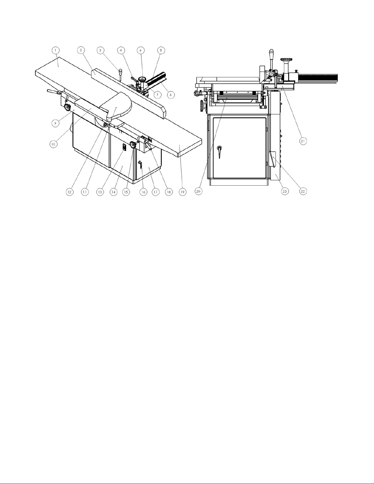
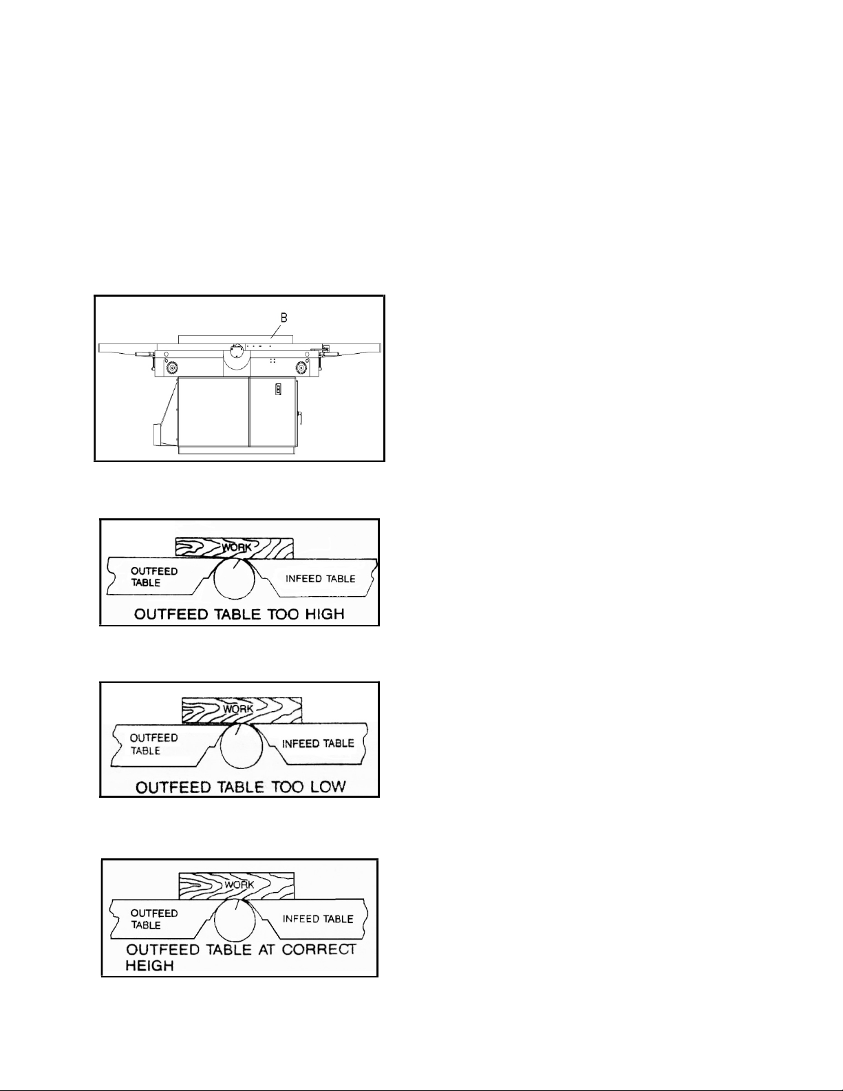
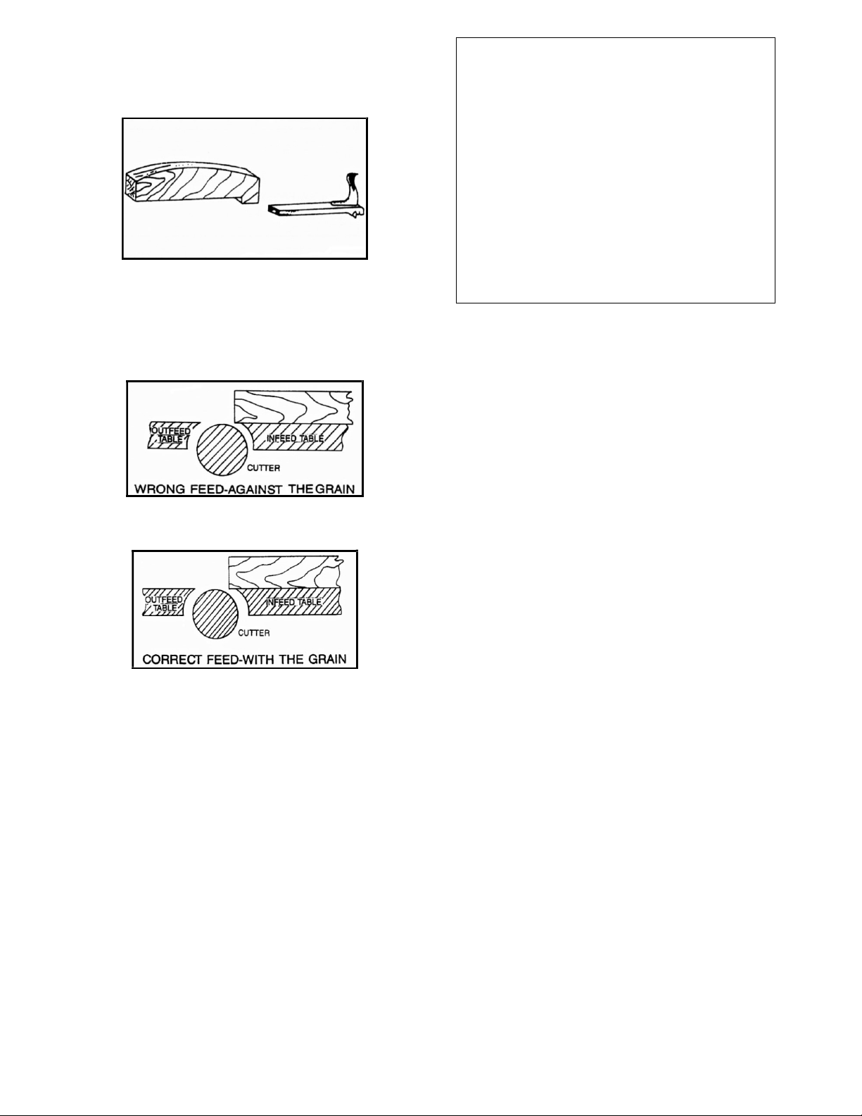
Cantek J168LH User manual

Operations & Parts
Manual
www.cantekamerica.com
Please ensure you have your serial number available when contacting us for parts or service.
J168LH
HEAVY DUTY 16”JOINTER

1
SPECIFICATIONS:
Cutting Capacity:
Maximum width ................................................................................................................................................................................. 16” (406mm)
Maximum depth of cut ....................................................................................................................................................................... 3/4” (19mm)
Table Size
Width .................................................................................................................................................................................................. 16” (406mm)
Length ............................................................................................................................................................................................... 96” (2438mm)
Height from floor ........................................................................................................................................................................ 31-1/2” (800mm)
Fence
Size (LxH) ................................................................................................................................................................. 47”x5-1/2” (1194x140mm)
Tilt degree .................................................................................................................................................................................................. 45 (F & R)
Positive Stops ............................................................................................................................................................................................ 45, 90, 135
Cutterhead
Speed ........................................................................................................................................................................................................... 5000RPM
Number of knives ...................................................................................................................................................................................................... 4
Diameter .................................................................................................................................................................................... 3-15/16” (100mm)
Cutting circle ............................................................................................................................................................................... 4-3/32” (104mm)
Rabbeting capacity ............................................................................................................................................................................... 34” (19mm)
Overall Dimension (LxWxH) ................................................................................. 97”x40”x37” (2464x1016x940mm)
Packing Dimension (LxWxH) .............................................................................. 102”x34”x40” (2597x866x1024mm)
Net Weight ............................................................................................................................................. 9901bs (450kgs)
Gross Weight ........................................................................................................................................ 12101bs (550kgs)
Standard Equipment:
1. Cutterhead guard
2. Tool sets: Spanner 10x12 1pc, 12x14 1pc, 17*19 1pc
Allen wrench 3, 5, 6, 8, 10mm * 1pc
3. 6” dia. Nozzle exhaust hood

2
FEATURES OF YOUR JOINTER
1. Outfeed Table
2. Fence
3. Fence Handle
4. Lock Handle
5. Support, Spur Gear
6. Control Handle-Forward/Backward
7. Rack
8. Safety Cover-Cutterhead
9. Middle Base
10. Rabbeting Ledge
11. Cutter Guard
12. Plastic Knob
13. PB Switch
14. Base
15. Table Lock
16. Door Handle
17. Stand Door
18. Handle-Table Raising/Lowering
19. Infeed Table
20. Exocentric Shaft
21. Fence Base
22. Wiring Box
23. Safety Cover-Driving Belt

3
INTRODUCTION
We thank you for your purchase of a 16" Jointer. It has been
designed, engineered and manufactured to give you the best
possible dependability and performance. However, we'd like to
remind you that faultless running is entirely dependent upon
rational use and careful maintenance, which will also spare you
time-consuming delaysand costly repairs. The following details
should accompany and correspondence relating to the machine.
Serial Number:
Model Number:
Manufacture Date:
The model, serial number, and manufacture date will be found on
the model plate attached to the machine.
You should record above information and keep in a safe place for
future reference.
REPLACE WARNING LABELS IF TH-
EY FALL OFF OR WEAR OFF.
CAUTION
KEEP HANDS AWAY FROM
CUTTERHEAD!
If you received a damaged jointer, immediately contact the dealer
that sold you the machine.
Save time and money. Before you request service, check for
Trouble Shooting on pages 10, 11. It lists causes of minor operating
problems that you can correct yourself.
GENERAL SAFETY RULES
As with all power tools there is a certain amount of hazard involved
with the operator and his use of the tool. Using the tool with the
respect and caution demanded as far as safety precautions are
concerned will considerably lessen the possibility of personal injury.
However if normal safety precautions are overlooked or completely
Ignored, personal injury to the operator can develop.
There are also certain applications for which this tool was designed.
We strongly recommend that this tool NOT be modified and/or
used for any application other than for which it was designed. If
you have any questions relative to its application DO NOT use the
tool until you have written us and we have advised you.
KNOW YOUR POWER TOOL.
Read the owner's manual carefully. Lean the tools applicatio-
nsand limitations, as well as the specific potential hazards
peculiar to it.
KEEP GUARDS IN PLACEand in working order.
REMOVE ADJUSTING KEYS AND
WREN-CHES.
From habit of checking to see that keys and adjusting
wrenches are removed from tool before turning it on.
KEEP WORK AREA CLEAN.
Cluttered areas invite accidents.
AVOID DANGEROUS ENVIRONMENT.
Don't use power tools in damp or wet locations. Keep your
work area well illuminated.
KEEP VISITORS AWAY.
All visitors should be kept a safe distance from work area.
MAKE WORKSHOP CHILDPROOF. With padlocks,
master switches, or by removing starter keys.
DON'T FOROE TOOL.
It will do the job better and safer at the rate for which it was
designed.
USE RIGHT TOOL.
Don't force tool or attachment to do a job which was not
designed for.
WEAR PROPER APPAREL.
No loose clothing or jewelry to get caught in moving parts.
Rubbersoled footwear is recommended for best footing.
USE SAFETY GLASSES.
Also use face or dust mask if cutting operation is dusty.
SECURE WORK.
Use clamps or a vise to hold work, when practical. It's safer
than using your hand and frees both hands to operate tool.
DON'T OVERREACH.
Keep your proper footing and balance at all times.
MAINTAIN TOOLS IN TOP CONDITION.
Keep tools sharp and clean for best and safest performance.
Follow instructions for lubricating and changing accessories.
DISCONNECT TOOLS.
Before servicing and when changing accessories such as
blades, bits, cutters, disconnect machine from power source.
USE RECOMMENDED ACCESSORIES.
Consult owner's manual. Use of improper accessories may be
hazardous.
CHECK FOR DAMAGED PARTS
Before further use of the tool, a guard or other part that is
damaged should be checked to assure that it will operate
properly and perform its intended function - check for
alignment of moving parts, binding of moving parts, breakage
of parts, mounting, and any other conditions that may affect
its operation. A guard or other part that is damaged should be
properly repaired or replaced.

4
ADDITIONAL SAFETY RULES FOR
JOINTERS
1. KEEP cutterhead sharp and free of all rust and pitch.
2. ALWAYS use a push block when jointing stock that does
not give a reasonable distance of safety for your hands.
3. NEVER PASS HANDS DIRECTLY OVER
CUTTERHEAD.
4. ALWAYS MAKE SURE THAT REAR CUTTER
GUARD IS IN PLACE WHWN JOINTING
NEAR THE FRONT EDGE WITH THE FENCE
TOWARDS THE FRONT.
5. DO NOT performs jointing operations on material shorter
than 8", narrower than 3/4", or less than 1/4"thick.
6. MAINTAIN the proper relationship of outfeed table
surface and cutterhead knife.
7. SUPPORT the work piece adequately at all times during
operation. Maintain control of the work at all times.
8. DO NOT back the work toward the infeed table.
9. DO NOT attempt to perform an abnormal or little used
operation without study and the use of adequate
hold-down/push blocks, jigs, fixture, stops, etc.
10. DO NOT makes cuts deeper than 1/8" in a single pass. On
cuts more than 1-1/2" wide, adjust depth of cut to 1/16" or less
to avoid overloading machine and to minimize chance of
kick-back.
UNPACKING AND CLEANING
Carefully unpack the jointer and all loose items from the wooden
case. Remove the protective coating from the machine surfaces of
the jointer.
This coating may be removed with a soft cloth moistened with
Kerosene or solvent (do not use acetone, gasoline or lacquer thinner
for this purpose). After cleaning, cover all unpainted surfaces with a
good quality paste wax.
LIFTING
Lift the planer on its provided trunnions with a nylon strap suitable
to lift 1320 LBS. SeeFig. 1
Fig. 1
INSTALLATION REQUIREMENT
Mount machine on a solid foundation, preferably a concrete floor.
The machine area should be clean, dry, well ventilated and well
lighted.
This machine equipped with noise-eliminating table lips. Even
though, the jointer also can create noise during long period of time
of operation. The site should be one which minimizes reverberant
sound from walls, ceilings and other equipment. Electric facilities
should be installed so that they are protected from damaging and
exposing. Be sure the machine frame is properly grounded. (See
"Power Source Wiring").
Inspection:
1. Cleaning protective coating from all areas and lubricated
parts.
2. Before connecting power to the machine, check if all screws
are tightened, all mechanical functions work freely, and the
cutterhead turns freely without touching the table lips.
Periodical or regular inspections are required to insure that
the machine is in good condition. Don't let dust accumulate in
the electrical enclosures. Be sure that there are no loose or
worn electric connections.
Power Source Wiring
CAUTION
Make sure the electrical characteristics are the same between the
motor nameplate and the power source. Make sure the power
circuit of the jointer is properly fused and that the wire size is
correct.
IN ALL CASES, MAKE SURE THE RECEPTACLE
IS PROPERLY GROUNDED.
USE QUALIFIED ELECTRICIAN FOR ELECTRICAL
CONNECTIONS.
1. Check the motor and switch wiring diagram for proper
voltage connections before applying power to the machine.
2. Connect wires between electric connection box and power
source. The ground wire must be connected.
Power source: R, S, T
Motor source: R1, S1, T1
Grounding: GR
Please refer to Fig. 2

5
3. After wire connection is complete turn the drive motor on
momentarily to check if it is on the proper direction.
4. Run the machine without cutting for a short period of time to
check if that all powered functions are operating properly.
Belt Adjusting
Remove the three knurled nuts and the belt guard for accessing to
the drive motor. Lower the motor mount plate on the adjustment
screw for desired belt tension. Counter lock adjusting screws (B)
See Fig. 3
NOTE: PLEASE CHECK THE V-BELT TENSION
AFTER THE FIRST TWO DAYS OF
OPERATION. BELTS WEAR DURING
INTIAL OPERATION.
Fence Installation
Install the fence on the jointer with the provided 1/2” (12.7mm)
cap screws and washers (A) as shown in Fig. 4
Fig. 2
Fig. 3
Fig. 4
ADJUSTMENTS AND OPERATION
WARNING
Disconnect machine from the power source before adjusting this
machine.
Fence Adjustment
Adjusting fence angles, (refer to Fig. 5)
1. Loosen handle (B), hold knob (C) to open an iron plate at 90
degree.
2. Pull fence (A) backward to obtain the required angle.
3. Locking handle(B). Limitation of fence tilting backward is at
the 135° positions. Screw (E) as shown in Fig. 5 is for
stopping the fence tilt.
4. The fence is at the stop of 90°; adjust screw (F) for vertical
position.
5. Two screws (G) under sliding support are for tilting forward
to 45° position as shownin Fig. 5.
Adjusting fence forward / backward
1. Loosen handle (H) Fig. 5
2. Adjust handwheel (I) to meet the position required.
3. Lock handle (H) to fasten fence.
Fig.5

6
Knives Removing
After a period of using the dull knives should be replaced or
reground. To remove the knives,
1. Release lock screws (C) on knife (A) and knife gib (B) Fig. 6.
2. Remove the knife and knife gib.
3. Remove two springs (D) placed below the knife (A).
Fig. 6
A. Knife
B. Knife gib
C. Lock screw of knife gib
D. Knife lifting spring
Knives Setting
If the knives are removed from the cutterhead for replacement or
regrinding, care must be used in re-setting them, process as follows:
1. DISCONNECT MACHINE FROM POWER SOURCE.
2. Pull hand lever (A) to lower infeed table as shown in Fig. 7
3. Place setting gauge on table with 5/64" or .080" gap between
cutterhead. Use feeler gage or dial indicator for accurate
setting.Fig. 8
4. Slip knife and knifegib (B) into place and tighten lock screws
(C) lightly. Fig. 9
5. Rotate cutterhead backwards by hand and adjust knife until it
just touches the gauge (D).Fig. 9
6. Using a bar to check knife at both end so that it is parallel to
table surface then tighten the screws.
7. Insert the other two knives and repeat above instructions.
8. Recheck knife setting by rotating cutterhead
WARNING
LOOSE GIB SCREWS CAN RESULT IN KNIVES BEING
THROWN OUT OF THE CUTTERHEAD CAUSING SEVER
DAMAGE TO THE MACHINE AND POSSIBLE SERIOUS OR
FATAL INJURY TO THE OPERATOR OR BYSTANDERS.
Fig. 7
Fig. 8
Fig. 9
Outfeed Table and Knife Adjustment
For accurate work in most jointing operations, outfeed table must be
exactly level with the knives at their highest point. This means, that
the knives must be parallel to the table and project equally from the
cutterhead.
To check these alignments proceed as follows:
1. DISCONNECT THE JOINTER FROM POWER SOURCE.
2. Raise or lower the outfeed table as required, until the outfeed
table is exactly level with the knives of the cutterhead at their
highest point of revolution.
3. Place a straight gage (B) on the outfeed table, extending over
the cutterhead as shown in Fig. 10
4. Rotate the cutterhead by hand. Loosen the lock screws in the
knife gib slightly, shift the knife until it just touches the

7
straight gage (B), and tighten the screws securely.
After the outfeed table has been set at the correct height, it should
not be changed except for special operations.
1
If the outfeed table is too high, the result will be as shown in Fig.
11. The finished surface will be curved.
If the outfeed table is too low, the condition will be as illustraed in
Fig. 12. The work will be gouged at the end of the cut.
As a final check of the outfeed table adjustment, run a piece of
wood slowly over the knives for 6 to 8 inches should rest firmly on
both tables as shown Fig. 13 with no open space under the finished
cut.
Fig.10
Fig. 11
Fig.12
Fig. 13

8
The Depth of Cut
The thickness which will be cut out is determined by the distance
between the height of infeed table and knife tip of cutterhead.
1. Loosen table lock (C) Fig. 14
2. Push or pull hand lever (A) to raise or lower table, gage (B)
shows the distance the table has been raised or lowered as
shown in Fig. 13
3. Maximum cutting capacity of this jointer is 3/4” each time.
The following directions will give the beginner a start on jointer
operation. Use scrap pieces of lumber to check settings and to get
the feel of the operations before attempting regular work.
ALWAYS USE GUARD AND KEEP HANDS
AWAY FROM CUTTERHEAD.
Fig. 14
Placement of hands During Feeding
First use left hand holds the work firmly against the infeed table and
fence while the right hand pushes the work toward the knives.
Through the cutterhead the new surface rests firmly on the outfeed
table as shown in Fig. 15. Then the left hand should press down at
the same time keep it contacting with the fence. Before the right
hand almost touches the cutterhead, it should move to the work
piece which already on outfeed table.
NEVER PASS THE HAND DIRECTLY OVER THE
CUTTERHEAD.
Fig. 15
Jointing an Edge
This is the most common operation for the jointer. Set guide fence
square with the table. Depth of cut should be the minimum required
to obtain a straight edge. Hold the best face of the piece firmly
against the fence throughout the feed.

9
Jointing Warped Pieces
When joint short or thin pieces, use a push block to eliminate all
danger to the hands. Two types are shown in Fig. 16. Push blocks
are easily made from scrap material.
Fig. 16
Direction of Grain
Feeding against the grain will cause chipping and splintering edges.
Fig. 17
Feeding with the grain obtain a smooth surfaceas shown in Fig. 18.
Fig. 17
Fig. 18
Beveling
To cut a bevel, lock the fence at the required angle and run the work
across the knives while keeping it firmly against the fence and table.
Several passes may be necessary to arrive at the desired result.
WARNING
ALWAYS USE GUARD AND KEEP HANDS
AWAY FROM CUTTERHEAD!!
CAUTION
1. NEVER CHANGE THE POSITION OF
THE OUTFEED TABLE UNLESS IT IS
FOR SPECIAL APPLICATIONS.
2. KEEP OUTFEED TABLE AT ALL TIMES
LEVELING WITH KNIFE EDGE.
3. CHECK ALL SCREWS AND FASTENERS
OCCASIONALLY AND KEEP THEM
TIGHTENED SECURELY.
CUTTERHEAD MAINTENANCE AND
SERVICE
Cutterhead Service
The entire cutterhead assembly may be removed for cleaning,
bearing or blade replacement or any other cutterhead maintenance
procedures. To remove it, lower both feed tables to clear the
cutterhead. Remove the bearing, loosen stud and remove the entire
cutterhead assembly with bearings, studs and bearing housings.
When re-installing, be sure the curved seats of the base casting are
free of dirt, dust, grease, etc.
Repair cutterhead process as follow:
1. DISCONNECT MACHINE FROM POWER SOURCE.
2. Lower infeed and outfeed tables.
3. Loosen square head screw (1), take out knife gib (2), knife (3)
and lifting spring (4). Fig.19
4. Loosen two studs (5), remove the cutterhead assembly.Fig.20
5. Loosen lock screw (6) and pull out belt pulley (7) and key
(8).Fig.20
6. Take down screw (9) on both sides and also bearing cover
(10).Fig.20
7. Remove bearing housing (11), bearing (12) andthe
cutterhead(13).Fig.20
8. To re-install the cutterhead, just reverse above procedures.

10
Fig. 19
Fig. 20
1. Square head screw
2. Knife gib
3. Knife
4. Lifting spring
5. Stud
6. Lock screw
7. Belt pulley
8. Key
9. Screw
10. Bearing cover
11. Bearing housing
12. Bearing
13. Cutterhead
Whetting Knives:
After considerable use, the knives will become dull and it won’t be
able to do job accurately. Unless badly damaged by running into
metal or other hard material, they may be sharpened as follows:
1. DISCONNECT THE MACHINE FROM POWER SOURCE.
2. Use a fine carborundum stone; cover it partly with paper as
indicated as shown in Fig. 21 to avoid marking the table.
3. Lay the stone on the infeed table, lower the table and turn the
cutterhead forward until the stone lies flat on the bevel of the
knives as shown.
4. Hold the cutterhead from turning, and whet the beveled edge
of the knife, stroking lengthwise by sliding the stone back
and forth across the table.
5. Do the same amount of whetting on each of the three blades.
Fig. 21
Blade Care
When blades become dull enough so that it is noticeable when
cutting, they should be resharpened. A sharp blade works easier and
results in longer blade life. The penalty paid for a dull blade is less
blade life; poor finish and wear on all parts of the machine.
When the knives cannot be properly retouched as described in
"Whetting Knives", they must be ground for a sharp edge without
nicks.
IF THE JOINTER IS USED OFTEN KEEP A SPARE SET OF
BALADES ON HAND AT ALL TIMES.
Gum and pitch which collets on the blades cause excessive friction
as the work continuous, resulting in over heating the blades, less
efficient cutting, and consequently loss of blade life. Use "Gum and
Pitch Remover"to wipe off the blades.
MAINTENANCE
In time rust may appear on the table and fence and other parts of the
jointer, resulting in less efficiency and accuracy of the machine.
Use paste wax which can be applied to prevent rust formation. If,
however, rust has already formed on these parts, use "Rust
Remover"which will restore the machine to its original accuracy
when applied.
LUBRICATION
The cutterhead runs in two single rows sealed and shielded ball
bearings, which are pre-lubricated for their entire life.

11
TROUBLE SHOOTING:
Symptom Possible Causes And Corrections
1. Finished stock is concaved on the end.
Check whether the knife tip is higher than outfeed
table.
Raise outfeed table so that the surface and knife
tip line are on same level as shown in Fig. 22
2. Back end of the finished stock is thicker than front
side.
Check if the outfeed table is higher than knife tip
line.
Adjust rear table to align with knife tip line as
shown if Fig. 23
Fig. 22
Fig. 23
TROUBLE SHOOTING (CONTINUED)
Symptom Possible Causes And Corrections
3. There is concave in the middle of finished stock. Check if the ends of both tables have a little fall.
To raise them adjust the screws which are four
corners under table as shown in Fig. 24, 26
4. Two tables are not in line. Adjust screws with nuts located at four corner
under the tables as shown in Fig. 24
5. Two ends of finished stock are cut more than the
middle.
Check if the ends of two tables are higher than the
middle.
Lower both table ends by adjusting screws under
the tablesas shown in Fig. 24& Fig. 25

12
Fig. 24
Fig. 25
Fig.26

13
PARTS LIST:
NO. PARTNO. DESCRIPTION Q"TY
1 C002009 Stand 1
2 P066001 Washer,Φ12 4
3 S284023 Spring Washer,Φ3/8 4
4 S100003 Hex. Head Screw,3/8"-16NC 4
5 C074013 Cover, Dust Chute 1
6 S239003 Screw, Dust Chute,3/16"-24NC 5
7 T004014 Assembly, Motor Pulley,2P-3HP 1
* T004041 Assembly, Motor Pulley,2P-5HP 1
* T004052 Assembly, Motor Pulley,2P-7 1/2HP 1
8 C022027 Plate, Switch 1
9 P074013P18 Contactor,HKP-18 1
10 P092303 Plastic bushing gland,M-25 3
11 S312001 Box, Junction 1
12 S284025 Spring Washer,Φ3/16 2
13 S313001 Strip, Terminal,30A 1
14 S239007 Screw, Dust Chute,3/16"-24NC 2
15 P082001 Switch,PP-2 1
16 C077026 Hood, Dust 1
17 S284024 Spring Washer,Φ1/4 7
18 S098001 Hex. Head Screw,1/4"-20NC 7
19 C073031 Door, Access 1
20 P027001 Assembly, Handle 1
21 C074027 Cover, Pulley 1
22 C034034 Screw,3/8"-16NC 3
23 S282052 Washer,Φ3/8"xΦ25 6
24 S273091 Nut,3/8"-16NC 6
25 S277001 Nut,3/8"-16NC 3

14

15
PARTS LIST:
NO. PARTNO. DESCRIPTION Q"TY
1 P041205R Motor,2P 3HP(2.2KW).R 1
* P040205R Motor,2P 3HP(2.2KW).R 1
2 C064038 Pulley,3HP 50HZ 1
* C064019 Pulley,3HP 60HZ 1
3 S214013 Fixed Screw,M10-P1.5 1
4 C063054 Bracket, Motor 1
5 S282011 Washer,Φ10.5 3
6 S284008 Spring Washer,Φ10.2 6
7 S137040 Hex. Head Screw,M10-P1.5 3
8 S273010R Nut,M10-P1.5 3
9 C015033 Plate 1
10 C048005 Rod 1
11 S282012 Washer,Φ13 2
12 S273012R Nut,M12-P1.75 6
13 S214014 Fixed Screw,M10-P1.5 1
14 S300053 Belt,A-53"L 2
* S300056 Belt,A-56"L 2

16
PARTS LIST:
NO. PARTNO. DESCRIPTION Q"TY
1 P041206R Motor,2P 5HP(3.7KW).R 1
* P040206R Motor,2P 5HP(3.7KW).R 1
2 C064039 Pulley,Φ139.7x58L;5HPx2P,50HZ 1
* C064040 Pulley,Φ114.3x58L,5HPx2P,60HZ 1
3 S214013 Fixed Screw,M10-P1.5 1
4 C063054 Bracket, Motor 1
5 S282011 Washer,Φ10.5 3
6 S284008 Spring Washer,Φ10.2 6
7 S137045 Hex. Head Screw,M10-P1.5 3
8 S273010R Nut,M10-P1.5 3
9 C015033 Plate 1
10 C048005 Rod 1
11 S282012 Washer,Φ13 2
12 S273012R Nut,M12-P1.75 6
13 S214014 Fixed Screw,M10-P1.5 1
14 S300055 Belt,A-55"L 2

17
PARTS LIST:
NO. PARTNO. DESCRIPTION Q"TY
1 P039127R Motor,2P7 1/2HP(5.5KW).R 1
2 C064039 Pulley,Φ114.3x58L,7 1/2HPx2P,60HZ 1
* C064040 Pulley,Φ139.7x58L,7 1/2HPx2P,50HZ 1
3 S214013 Fixed Screw,M10-P1.5 2
4 C063054 Bracket, Motor 1
5 S282011 Washer,Φ10.5 3
6 S284008 Spring Washer,Φ10.2 6
7 S137045 Hex. Head Screw,M10-P1.5 3
8 S273010R Nut,M10-P1.5 3
9 C015033 Plate 1
10 C048005 Rod 1
11 S282012 Washer,Φ13 2
12 S273012R Nut,M12-P1.75 6
13 S300051 Belt,A-51"L 2

18
PARTS LIST:
NO. PARTNO. DESCRIPTION Q"TY
1 C004047 Table Base 1
2 T001026 Cutterhead Assembly 1
3 S284023 Spring Washer,Φ3/8 14
4 S100004 Hex. Head Screw,3/8"-16NC 2
5 T012037 Infeed Table Assembly 1
6 T012038 Outfeed Table Assembly 1
7 S273091 Nut,3/8"-16NC 10
8 S100006 Hex. Head Screw,3/8"-16NC 16
9 P108102 Plate, Measure 1
10 C057039 Handle, Table Raising (L) 1
11 P051001 Bushing,Φ19.05 2
12 C046086 Hand Shaft 2
13 S284022 Spring Washer,Φ1/2 2
14 S277002 Nut,Φ1/2 2
15 C034142 Lock Bolt,1/2"-12NCx2 2
16 S282054 Washer,Φ1/2" 2
17 C057041 Handwheel 2
18 C052083 Collar 2
19 C052084 Bushing 2
20 S186006 Hex. Head Screw,3/8"-16NC 2
21 P089108 Hole Plugs,HP-30 2
22 C057031 Handle 2
23 C057045 Handle, Table Raising (R) 1
24 C020062 Block 2
25 S186010 Hex. Head Screw,3/8"-16NC 4
26 S273090 Nut,5/16"-18NC 4
27 S099007 Hex. Head Screw5/16"-18NC 2
28 C070006 Indicator 1
29 S284025 Spring Washer,Φ3/16 2
30 S239004 Screw, Dust Chute,3/16"-24NC 2
31 T025019 Cover Assembly, Cutterhed 1
32 C016116 Support, Table Fall 2
33 S284021 Spring Washer, Φ5/16 4
34 S099004 Hex. Head Screw,5/16"-18NC 4
35 S099011 Hex. Head Screw,5/16"-18NC 1
36 S099013 Hex. Head Screw,5/16"-18NC 1
37 T029003 16" Gage 1

19
Other Cantek Power Tools manuals