Storage & Safety Guidelines
To ensure maximum performance, store
Canusa products in a dry, ventilated area.
Keep products sealed in original cartons
and avoid exposure to direct sunlight, rain,
snow, dust or other adverse environmen-
tal elements. Avoid prolonged storage at
temperatures above 35°C (95°F) or below
-20°C (-4°F). Product installation should be
done in accordance with local health and
safety regulations.
These installation instructions are intended
as a guide for standard products. Consult
your Canusa representative for specific
projects or unique applications.
Canusa warrants that the product conforms
to its chemical and physical description
and is appropriate for the use stated on the
installation guide when used in compliance
with Canusa’s written instructions. Since
many installation factors are beyond
our control, the user shall determine the
suitability of the products for the intended
use and assume all risks and liabilities in
connection therewith. Canusa’s liability is
stated in the standard terms and conditions
of sale. Canusa makes no other warranty
either expressed or implied. All information
contained in this installation guide is to be
used as a guide and is subject to change
without notice. This installation guide
supersedes all previous installation guides
on this product. E&OE
Canusa-CPS
A division of Shawcor Ltd.
Head Office
25 Bethridge Road
Toronto, ON, Canada M9W 1M7
Tel: +1 416 743 7111
Fax: +1 416 743 5927
Canada
Dome Tower St. 2200,
333-7th Avenue SW
Calgary, AB, Canada T2P 2Z1
Tel: +1 403 218 8207
Fax: +1 403 264 3649
Americas
5875 N. Sam Houston Pkwy W.,
Suite 200
Houston, TX, USA 77086
Tel: +1 281 886 2350
Fax: +1 281 886 2353
Middle East
ADPC - Mussafah Port,
P.O. Box 2621
Abu Dhabi, UAE
Tel: +971 2 496 3500
Fax: +971 2 496 3501
Europe, Africa & Russia
Dellaertweg 9-E, Gebouw
“Le Carrefour”
2316 WZ Leiden,
The Netherlands (NL)
Tel: +31 71 80 802 70
Fax: +31 71 80 802 71
Asia-Pacific
101 Thomson Road,
#11-03 United Square
307591 Singapore
Tel: +65 6749 8918
Fax: +65 6749 8919
Quality Management system
registered to ISO 9001
Part No. 99060-204
IG_GTS-PE_rev019
17
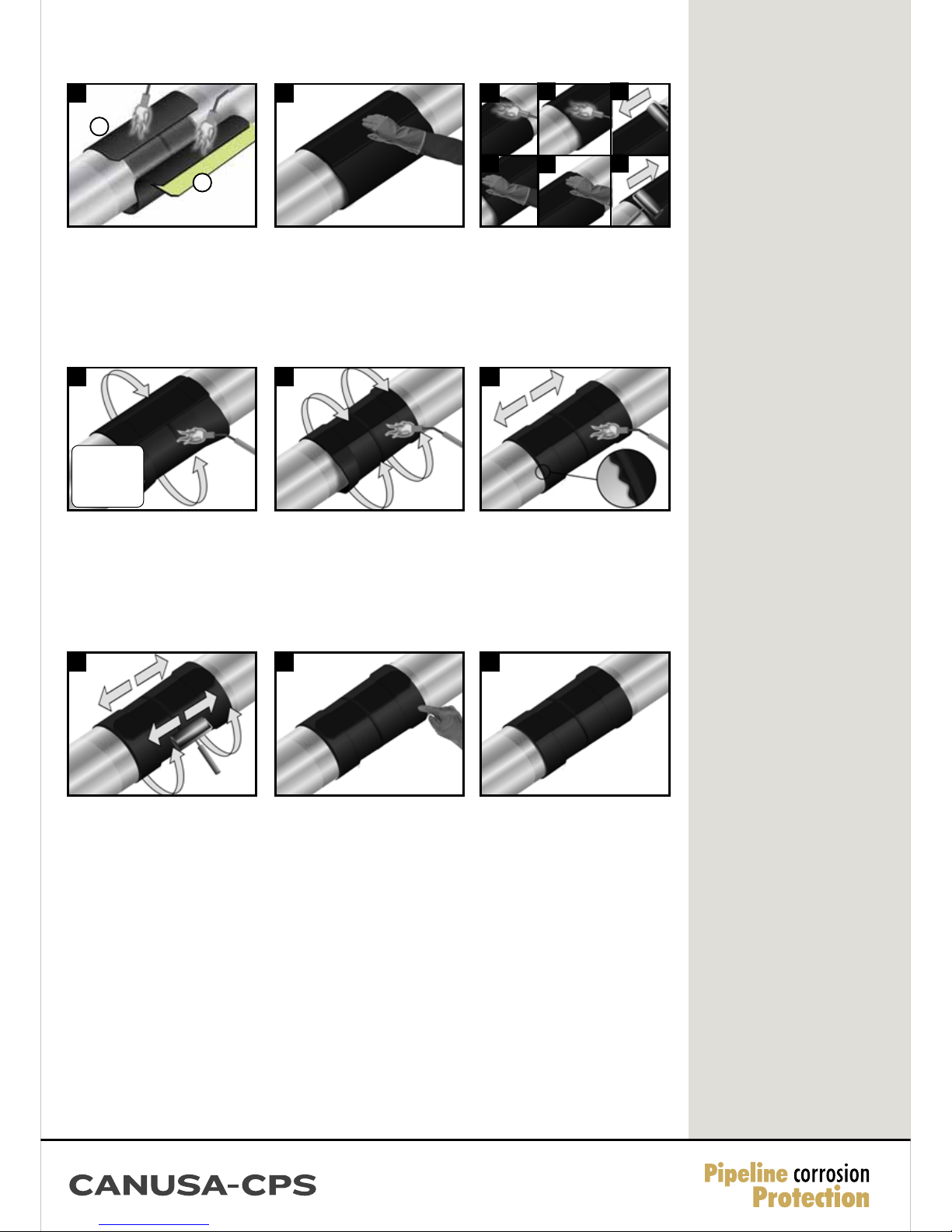
Continue heating from the centre toward one
end of the sleeve until recovery is complete. In
a similar manner, heat and shrink the remaining
side.
18
Shrinking has been completed when the
adhesive begins to ooze at the sleeve edges
all around the circumference. Finish shrinking
the sleeve with long horizontal strokes over
the entire surface to ensure a uniform bond.
19
While the sleeve is still hot and soft, use a hand
roller to gently roll the sleeve surface and push
any trapped air up and out of the sleeve, as
shown above. Continue the procedure by also
firmly rolling the closure with long horizontal
strokes from the weld outwards.
With the green-yellow coloured adhesive side
facing down, firmly press the entire closure
seal into place. Ensure that the closure is
centred evenly over the underlap-overlap
sleeve seam. If necessary, add additional heat
to the closure underside in cold conditions,
using a low flame intensity.
14 15
Gently heat the closure and pat it down with
a gloved hand. Repeating this procedure,
move from one side to the other. Smooth any
wrinkles by gently working them outward from
the centre of the closure with a roller.
C
BD
E
F
After shrinking is complete, allow the sleeve to cool to less than 90°C prior to laying (for offshore applications, product
can be water quenched).
Onshore and Offshore Guidelines
16
Using the appropriate sized torch, begin at the
centre of the sleeve and heat circumferentially
around the pipe. Use broad strokes. If utilizing
two torches, operators should work on
opposite sides of pipe.
Pipe O.D.
≤450mm (18”)
1 torch
>450mm (18”)
2 torches
20 21
Test sleeve adhesion by gently pulling the
edge of the backing back to ensure that the
adhesive remains in place and is fully bonded
to the factory coating. The sleeve is well
bonded when the adhesive and coating remain
intimately contacted. If required to improve
bonding, additional heat should be applied to
the sleeve.
Visually inspect the installed sleeve for the
following:
• Sleeve is in full contact with the steel joint.
• Adhesive flows beyond both sleeve edges.
• No cracks or holes in sleeve backing.
Quality Check - Adhesion Test Inspection
13
Wrap the sleeve loosely around the pipe,
ensuring the appropriate overlap.
Before finishing wrapping the sleeve:
1. heat the backing side of the underlap until
the backing starts to recover. Then use a roller
to secure the underlap to the pipe.
2. gently heat the green-yellow coloured adhe-
sive side of the closure seal until it appears
glossy.
1
2