Caple WC6400 User manual

1
/
27
WC6400/WC6410/WC6500
Service Manual
Herebelowwelistedvariousfaultswhileusingthewinecooler,and themethodofcheck-up andsolvethese
default,and findtheinformationofthecorrespondentpage.
Statement:(Fig.4)showsthereferencefigureFig4
(6.1.6)showsthereferenceitem6.1.6.
Warning:beforeattemptinganycleaningormaintenancethisunitMUSTbedisconnectedfromthe
electricalsupply, topreventelectricalshock
▲Preparationbeforemaintenance
○Tools
1.Pliers2.Phillipsheadscrewdrivers
3.Process pipe 4.ElectricalMultimeter
5.Ampmeter(5A)(calipercabletype)6.Electricalsolderingiron
7.Wirestrippers 8.Sealpliers
9. Scissors
○Equipment
1.Vacuumpump 2.Solderingironforcopperpipes 3. Refrigerant meter
1. Safety ruleson operation of repairing. 2
2. Electrical circuitdiagram. 4
3. Cooling system diagram. 6
4. Nameandfunctionon control panel. 6
5. Howto diagnose the fault. (E1、E2、E3、E4)7
6. Disassembly10
7. Howto maintain the default. 24

2
/
27
1. Safetyrules onoperationof repairing
(Rulesmustbeobeyed).
To avoid theaccident during maintain thewine cooler, and make surethe product issafety, rules
must be obeyed listbelow.
○Below we list the symbols and explain the danger if ignore it.
Danger This symbol means that the instancemay have the chance to suffer
death or a serious wound.
Warning This symbol means that the instancemay have the chance to suffer
death or a serious wound.’
Notice This symbol means that the instancemay have the chance to suffer
a wound.’
○Below symbols’distinguish and rules should be obeyed.
This symbolmeansthe
instance hope to be
noticed
This symbol means the
instance must be done
forcibly
This symbolmeansthe
instance forbidden
Danger
·Please make sure to discharge therest refrigerant in the parts.
·When discharging refrigerant, make sure thatit never go tothe fireplace
and drain to outdoors.
Tell the customers that they never close to thedischarge placeand the fire
is forbidden.
·Take apart the pipe by cutter.
Never take apart the part by soldering, otherwise it will fire the rest
refrigerantin the systems and cause blast.
·Exhaust the rest refrigerant in the systems before welding.
·After filling the refrigerantthe sealing should be doneby using smithing
welding nozzle.
Using the welding machine will firethe refrigerant and blast.
·Since theR600aisheavierthanthe air, please let the R600a onthe ground
go especially for the hypogeum.
·The operation onthe servicingrefrigerant bottle should be done in place
without fire and outdoors.
·Use therefrigerantwarnerplease,astherest refrigerantwillcausethe
fire.
·Don’t use fire in the place withrest refrigerant.
·Don’t place the default compressor in indoor.

3
/
27
Danger
·During repairing,the power plug should be disconnected.
Before remove, install, replace parts disconnect the power plug.
·Attentiondon’tget electric shock.
When checking current, voltage or chargingnever touch the connectors.
When changing the parts,don’ttouch the charged parts withinthree minutes
after disconnect the plug.
The capacitor will discharge for some time.
·Don’tdamage the cooling pipe, sine the refrigerant is flammable, the damage
will cause the fireor blast.
·Don’t smoking inthe service car.
·Dischargetherefrigerantentirely intheplacewithoutfirebefore disusing
the refrigerant bottle.
·Don’ttouch thewinecoolerwhen the cooling pipe damaged, don’tfieinside
the wine cooler, keep the windows open to exchange the air.
·Disusing the default compressor should be done outdoor without fire.
·The maximum weightof the refrigerantbottle loaded inthevehicleshould be
comply to stated, the bottle should beplace upright, the maximum leaning angle
is 40°.
·Do use the appointedpart, otherwise it have chance to smoke fire or default.
·Please put the defaultcompressor into plasticbag and seal theperistome,
then pack it with strip, as the restcompressor oil may leak in the vehicle and
cause fire or blast.
·Check if all the snails, parts,wiring are install in it’splace, ifthe area
around the service part worsen.
When measuringthegroundingresistancemakesure thatthetestrange is more
than 1MΩ.
Make surethepowercord and plug never bepinched on rear ofthewine cooler.
Exchange the power cord when it damaged.
Clean the flake of the plugwhen itdirty.
Notice
·Attentionthe hot.
The running or just stop compressor and the pipesometimes are very hot. And
the heatingor juststop heater is very hot. The hot willcause scald.
·Attentionthe hotparts of the pipe after the welding.

4
/
27
·Attention the refrigerant during charge and discharge it, as it will frostbite
the skin when touchit.
·Attentionthe burr.
The burr onthe metal or plastic part may hurtthe hand.
·Attentionthe fins of theevaporator.
The fins ofthe evaporator may hurtthe hand.
·Drive upthewinecoolerwhenmovingit. Pushingit maydamagethefloor.Cover
a protectorboard on the easy damage floor.
2. Electrical circuit diagram.
2.1NormalPCB

5
/
27
2.2 SwitchingpowersupplyPCB

6
/
27
3.Cooling systemdiagram.
4. Name andfunction oncontrol panel.
4.1StyleA
•POWER”ThisLEDlight on meansthe powerison.
•”Press it, theuppercompartmentsettingtempwill decreasein1.
•”Press it, thelowercompartmentsettingtempwill decreasein1.
•“Press it,thelighton,press again,thelightoff,itisnoteffectbythedoorswitch.Press it andholdonfor
three secondswill enterthetimeadjustment. Press ‘’toadjustthehour, press ’’toadjusttheminute.
“Press it onetime, thepoweron,press it andholdonforthree seconds, thepoweroff.
lThedefault settingtempofthiswinecoolerareuppercompartment6, lowercompartment12, butwhenrestartthe
winecoolerafterpoweroff, it will backtotheformersettingtemp beforepoweroff.

7
/
27
4.2StyleB
•”Press it, theuppercompartmentsettingtemp will decreasein1.
•”Press it , thelowercompartmentsettingtempwill decreasein1.
•“”Press it, thelighton, press again, thelightoff,it isnoteffectbythedoorswitch.
•“”Press it, poweron;press itandholdonforthreesecondspoweroff.
•“Left display”isupper chamber display.
•“Right display”is lower chamber display
lThe default setting temp of this wine cooler areupper compartment6, lower compartment 12, but
when restart thewinecoolerafterpoweroff, it will back to theformersetting tempbefore
power off.
Notice:
According to customers’requirement, thiswinecooler can be setto that the readout display
actual tempor setting temp.
a. In the readout display actual temp mode, press the ‘▲’ or ‘▼’, the systems enter the
temperaturesetting mode and the setting temperature twinkling. Five seconds twinkling after
stopping adjusttemperature,thereadoutstoptwinkling andthereadout show actual temperature,
the temperature setting mode end.
b.In the readout display actual tempmode, press the ‘▲’ or ‘▼’, the systems enterthe
temperaturesetting modeandthe settingtemperature twinkling.Fivesecondstwinklingafter
stopping adjust temperature, the readoutstop twinkling and thereadout show actual temperature,
the temperature setting mode end.
Notice:Ifanydoubt, pleaserefertotheusermanual.
5.Howto diagnosethefault.
5.1 Fault findingbytheself-checkmode.
Thewinecooleriscontrolledby electronicController,inordertomaintainthewinecoolereasily,thereisa
self-checkfunction inthecontrolPCB.

8
/
27
If yoususpectthatthecontrolsystemfault, youcanstartheself-checkmodebyfollowingbelow:
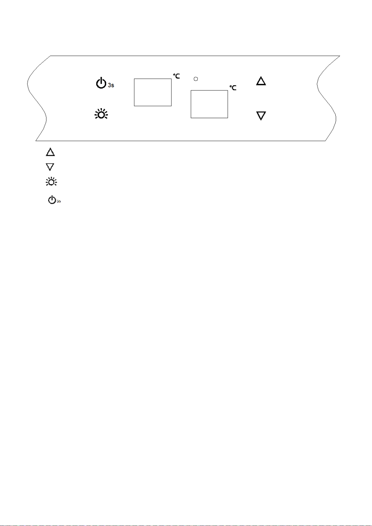
1>.Poweronthewinecooler,it will beeponesound,thewinecoolerstar,within10 secondsafterit start,
press the ‘▲’and‘▼’atthe same time and holding, threebeepwillsound,thesystems enter
self-check mode.
The power indication light on.
The readouts show the actual temperatures.
The heater on and last for ten seconds
The LED light on.
All of the inner and outer fans running.
No responsewhen touch the controlled button.
2>.If all tallywithabovedescription,thepartsarenormal.If anypartfail,checkthefailedpartand the
correspondingwiringandconnection,ifthewiring andconnection isingoodcondition,replacethepartand
checkagain, ifit still failed, thedefault shouldbethecontrolPCB, replace itwithsamemodel. ( 6.2.2 )
3 >.Theself-checkcanbequit onlydisconnectthepowerplug.
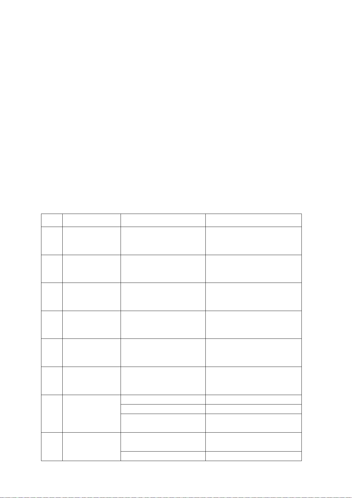
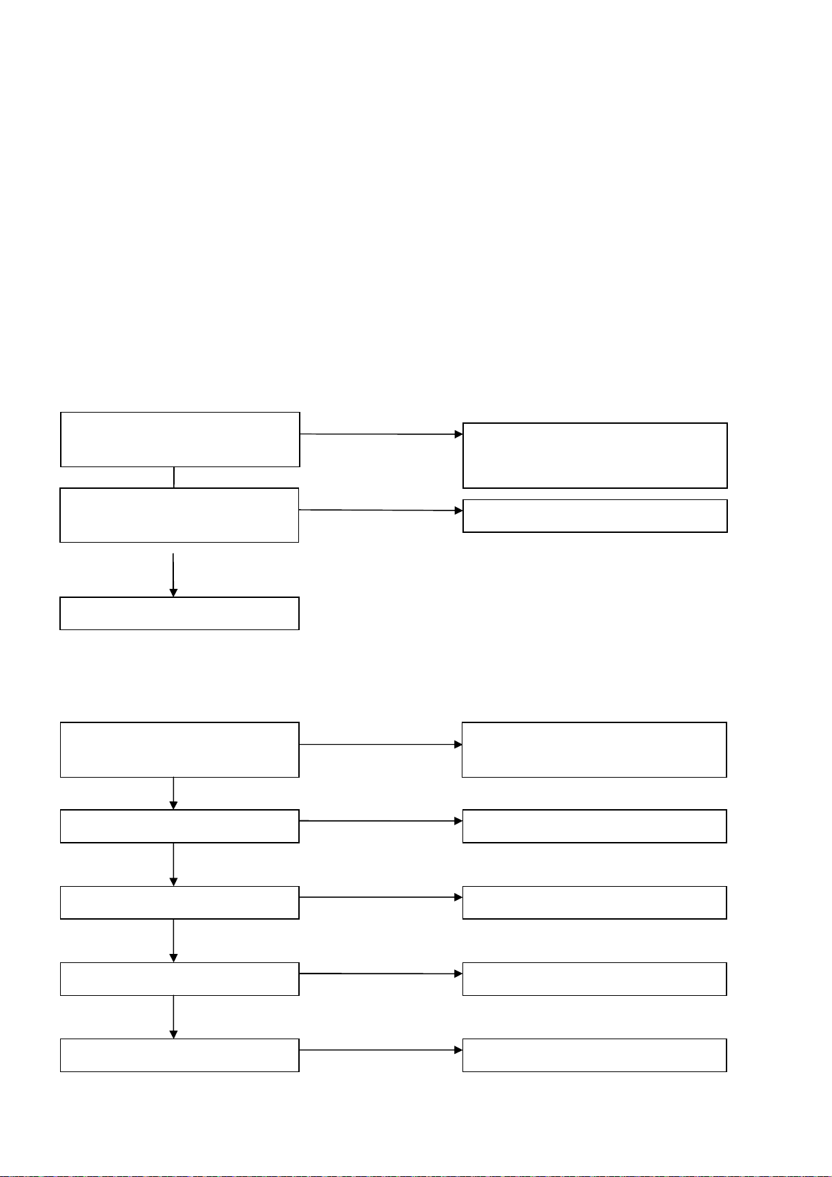
5.2Errcode
Code
Representation Checkingpoint Solution
E1 Uppercompartment
sensoropencircuit
Checkthewiringand connection
betweenPCB andsensor,ifitopen
circuit.
If theconnectionandwiringisnormal,
replacethesensorplease.
E2 Uppercompartment
sensorshort circuit
Checkthewiringand connection
betweenPCBandsensor,ifitshort
circuit.
If theconnectionandwiringisnormal,
replacethesensorplease.
E3 Defrostsensoropen
circuit
Checkthewiringand connection
betweenPCB andsensor,ifitopen
circuit.
If theconnectionandwiringisnormal,
replacethesensorplease.
E4 Defrostsensorshort
circuit
Checkthewiringand connection
betweenPCBandsensor,ifitshort
circuit.
If theconnectionandwiringisnormal,
replacethesensorplease.
E7 Lowercompartment
sensoropencircuit
Checkthewiringand connection
betweenPCB andsensor,ifitopen
circuit.
If theconnectionandwiringisnormal,
replacethesensorplease.
E8 Lowercompartment
sensorshort circuit
Checkthewiringand connection
betweenPCBandsensor,ifitshort
circuit.
If theconnectionandwiringisnormal,
replacethesensorplease.
HI Innertemperaturetoo
high
ACheckifanyrefrigerant leakage. Repairtheleakageandrefill.
BCheckifthecapillaryjam Cleanorreplacethecapillary.
CCheckittheinnerfanrun
normally Repairthewiringorreplacethefan.
LO Innertemperaturetoo
low
aCheckiftheinnerfanrun
normally Repairthewiringorreplacethefan.
bCheckifthePCBnormal. ReplacethePCB.

9
/
27
“HI —Hightemperaturewarning.Afterturningonthewinecoolertenhours,iftheinnertemperatureisover23ºC,the
readoutshowHI,afteritshowingforonehour,the “HI twinklingandthebuzzeralarm,andtwentyminutes
later,thebuzzerstop,thecompressorstop,thereadoutkeeptwinkling.TheHIalarmcanbestoppedby
disconnectthepowerplug.
“LO —Lowtemperaturewarning.Afterturningonthewinecoolertwohours,iftheinnertemperatureislowerthan0 ºCand
lastingfor15minutes,thereadoutshow “LO ,thebuzzeralarm, andthecompressorstopatthesametime,
whentheinnertemperatureisover2ºC,theLOwarningstop.
*Remark:somemodelswithouttheHIandLOwarningfunction.
5.3Diagnosethedefaults
●Thereisn’tanydisplay onthedisplay PCB.
●Notcooling(thecompressorstop)
No
Yes
No
No
Yes
Yes
Yes
No
If theinnerlightcanbeturnon Checkthepowersource (powercord,
plug, socket)
Displayerrorcode? Referto5.2.
Thestarterhavepowerinput?
Theprotectorhavepowerinput?
Checkthecompressor
Thestarterfailed
Theprotectorfailed
Compressorfault
Yes
Yes
If theinnerlightcanbeturnon Checkthepowersource (powercord,
plug, socket)
CheckthePCB circuit
DisplayPCB failed
No
If thedisplayhavepowerinput
No

10
/
27
●Notcooling(thecompressorrunning)
6.Disassembly.
Warning: Disconnect the power plug before maintain the wine cooler.
6.1 Disassemblingtheinnercabinet.
6.1.1. How toremove the shelves.
Pushtheshelftotheend, and revolvetheshelfoneitherside,makethestopperon theoutoftheguiding
rail, thenpulltheshelfout (Fig.1).
No
Yes
No
Yes
No
No
Yes
Thecompressorrunformorethan30 minutes?
If thedooropenedfrequently? Don’topenthedoorfrequently
If thehotgoodswasputintothe
cabinet?
If thedoorgasketairproof?
Coolingsystemdefault.?(Checkifany gasleakageorblock )
Itcanbeloadedwithnormaltemperature
winebottle
Repairorreplace thegasket
Fig.1
Shelves

11
/
27
6.1.2. How toremove the air-ductboard
There are twostructures
6.1.2.1StyleA
Theprocess ofremovingtheair-ductboard:Removeall shelves Remove controlpanelfilm Remove
the display supporter Remove the middle electrical box Remove the upperand lower air
duct board Remove the back air-duct board
1. Peeloffthecontrolpanelfilm
Removeallshelves Remove controlpanelfilm
Remove all shelves, then peel off the control panel film. Be careful don’tdamage the
control panel file, as it have to be fixing again. (Fig.2)
2. Remove the display supporter
The process: Remove the shelves Remove thecontrol panel film Remove the screws
Remove the display supporter.
Removetheshelves,afterremovingthecontrolpanelfilm (Fig.2),removethescrews(A)and(B),
disconnectthewiringconnector, and wecanremovethedisplaysupporter. (Fig.3)
Controlpanelfilm
Fig.2

12
/
27
3. Remove the middle electrical box
The process: Remove the shelves Remove thecontrol panel film Remove the screws
Remove the display supporter Remove themiddle electrical box
Remove theshelves,removethe control panelfilm and c ontrolbox (Fig.2, Fig.3),Remove the
four middleelectrical box fixing screws,disconnect the light connecter,removethe
middle electricalbox. (Fig.4)
ScrewsB
Screws
A
Controlbox
Fig.3
Middleelectrical
box
LEDlight
connector
Screws
Fig.4

13
/
27
4. Remove the upper and lower air-ductboard
The process: Remove the shelves Remove thecontrol panel film Remove the screws
Remove the display supporter Remove the middle electrical box Remove the screws
Remove the upper and lowerair-duct board.
Remove the shelves, remove the control panel film and control box (Fig.2,Fig.3),Remove
the fourmiddleelectrical boxfixingscrews, disconnectthelightconnecter, remove
the middle electrical box (Fig.4),remove the middle air-duct board fixing screws, remove
the middle air-duct board (Fig.5).
5. Remove the inner air-duct board
The process: Remove the shelves Remove thecontrol panel film Remove the screws
Remove the display supporter Remove the middle electrical box Remove the screws
Remove the upper and lowerair-duct board. Remove the inner air-ductboard
1)After removethe upperand lower air-ductboard (Fig.5),remove the innerair-duct board
fixing screws, and then remove the innerair-duct board.
Upper
air-duct
board
Lower
air-duct
board
Screws
Screws
Fig.5

14
/
27
2)Afterremovingtheinnerair-ductboard,wecansee suctionpipeand capillarypipejoint
(Fig.7)
A:Capillarysolderjoint. B:Suctionpipesolderjoint
C:Uppercompartmentfanconnector D:Uppercompartmentsensorconnector
E:Heaterfanconnector F:Heaterconnector
G:Defrostsensorconnector H:Aircyclingfanconnector
I:Lowercompartmentsensor J:Evaporator
Screws
Inner
air-duct
board
Fig.6

15
/
27
6.1.2.2 StyleB
The process of removingthe air-duct board: Remove all shelves Remove controlpanelfilm
Remove the middle electrical box Remove thedisplay supporter Remove the upper and
lower air duct board Removethe back air-duct board
1.Remove the middle controlbox
The process: Remove the shelves Remove the screws Remove the middle electrical box
Remove the shelves, Removethe middleelectrical box fixing screws, disconnect thelight
connecter, removethe middleelectrical box. (Fig.7.1)
2.Remove the control box
The process: Remove the shelves Remove thecontrol panel film Remove the screws
Fig.7
C
D
E
F
G
H I
J
B
A
Fig.7.1

16
/
27
Remove the middleelectricalbox Remove the display supporter.
Remove the shelves, after removing thecontrolpanel film(Fig.2),remove the fourfixing
screws, disconnect the light connector, removethe middle electrical box (Fig.7.1),and
we can disconnectthe connector of display and remove the display supporter. (Fig.7.2)
3. Remove the upper and lower air-ductboard
The process: Remove the shelves Removethe screws Remove the middle electrical box
Remove the display supporter Remove the screws Remove the upper and lower air-duct
board
Removetheshelves, Remove upper panel of the middle air-duct board, disconnectthe display
connector. Pull control boxto either of the sideto remove the middle control box (Fig.7.1).
Removethedisplaysupporter (Fig.7.2).Removetheupperand lowerpanelofthemiddleair-ductboard
(Fig.5).
4. Remove the inner air-duct board
The process: Remove the shelves Remove thescrews Remove the middlecontrol box
Remove the display supporter. Remove the upper and lower air-duct board Remove the
screws- Remove the inner air-duct board.
Removetheshelves, remove the middle control box (Fig.7.1).Removetheupperand lowerpanel
ofthemiddleair-ductboard (Fig.5). Removethescrewsfixingbackair-ductboard,disconnectthe
connectorand removethebackair-ductboard (Fig.6).
6.1.3.How toremove theevaporator
The process: Remove the shelves Remove the control panel film(not for styleB) Remove
the screws Remove the display supporter Remove the middle control box Removethe
screws Remove the upper andlower air-duct board. Remove the air-ductboard A.
Separate the evaporator from the compressor and dry filter on the joints.
After removing the inner air-duct board according to above, you canseetheevaporatoris
jointing to suction pipe and capillary(Fig.7 ).Heat the joint E,G (Fig.17 )in the
compressor room, and disconnect the pipe from compressor by using thepliers. Then remove
the evaporator and capillary and suction pipe upward.
Fig.7.2

17
/
27
6.1.4. How toremove the display PCB
6.1.4.1StyleA
Theprocess:removethedisplaysupporter Remove the display PCB
Afterremovingthedisplaycontrolbox(6.1.2.),pullthehooksfromthebackofit,and removethe
displayPCB.(Fig.8&Fig.8.1)
6.1.4.2StyleB
Theprocess:Removethedisplaysupporter remove the display PCB
Removethecontrolbox(6.1.2.),pull thecontrolboxupperand lowerpartsoutward,and takethe
displayPCBand it’ssupporterout (Fig.8.2). pull thehooksand removethedisplayPCB.
Controlbox
Fig.8 Fig.8.1
DisplayPCB
Display
supporter
DisplayPCB
Controlbox
Fig8.2

18
/
27
6.1.5. How toremove the inner fans
The process: Remove the shelves Remove thecontrol panel film Remove the screws
Remove the display supporter Remove the middle electrical box Remove the screws
Remove the upper and lower air-duct board. Remove the inner air-duct board Remove
the fan fixing screws Remove the fan
After remove the inner air-duct board(6.1.2.), removethe fans fixing screwsand we can
remove the fan.(Fig.9)
6.1.6. How toremove the heater
The process: Remove the shelves Remove thecontrol panel film Remove the screws
Remove the display supporter Remove the middle electrical box Remove the screws
Remove the upper and lower air-duct board. Remove the inner air-duct board Remove
the heater fixingscrews Remove the heater
Innerair-duct
board
Upperfan
Lowercompartment
fan
Heaterfan
Screws
Screws
Screws
Fig.9
Hooks
挂钩
Fig.8.3

19
/
27
After removing the air-duct board(6.1.2.),the heater is on the backof it, remove the fixing
screws and we can remove the heater.(Fig.10)
6.1.7. How toremove the defrost sensors
The process: Remove the shelves Remove thecontrol panel film Remove the screws
Remove thedisplaysupporter Remove the middle electrical box Remove the upper
air-duct board remove the sensor cover remove the sensors
1. Howto remove the defrost sensor and upper compartmentsensor.
Remove the upper air-duct board(A)(6.1.2.),pullout the two expanding nails(D) by pressing
from rear with hardtool, the sensor cover(C) loose, pullout thesensor (B). (Fig.11)
2. How to remove the lower compartmentsensor
The process: Remove the shelves Remove the lower air-duct board removethe sensor
Removetheshelves,removethelowerair-ductboard,wecanseethelowercompartmentsensor,removethe
sensorfixingscrewandremovethesensor (Fig.7)
6.1.8.How to remove theLED light.
1. How to remove the lower compartment LEDlight.
The process: Remove the shelves Remove the control panel film Remove the screws
Remove the display supporter Remove the PCB
①.Removetheshelves, peeloffthecontrolpanelfilm, removethemiddleelectricalbox. (Fig.2&
Fig.3&Fig.4)
②.Disconnecttheconnector,press theheadofthenailsonebyone,pullthelightPCBupward,
Screws
Heater
Backofthe
innerair-duct
board
Fig.10
Fig.11

20
/
27
and wecanremovetheLEDlight. (Fig.12&Fig.12.1)
2.HowtoremovetheuppercompartmentLEDlight.
Theprocess:Removetheshelves Removethelightcoverfixingscrews Removethelightcover
Remove the LED light fixing screws RemovetheLEDlight.
①,Removetheshelves. (Fig.1)
②,Removetwolightcovefixingscrews, removethelightcover. (Fig.13)
③,RemovetheLEDlightfixingscrewinthemiddleofit,removetheLEDlight. (Fig.13.1)
Fig.13.1
Middle
electrical
box
Foaminthe
middle
electrical
box
LEDconnector
LEDlight
Fig.12
Screws
Screw
Fig.13
Fig.12.1
Nails
Light
Other manuals for WC6400
1
This manual suits for next models
2
Table of contents
Other Caple Kitchen Appliance manuals