WARNINGS
The appliance is not intended for use by
young children or inrm persons without
supervision. Young children should be su-
pervised to ensure they do not play with
the appliance.
The air sucked can’t be conveyed throu-
gh or into a duct used to let out fumes
from appliances fed by energy other than
electric power (eg. centralized heating, ra-
diators, water-heaters, etc.).
To evacuate the air outlet, please comply
with the pertaining rules given by compe-
tent authorities.
Provide the room with an adequate aeration
when a cooker hood and appliances fed by
energy other than electric power (gas-, oil-,
or coal- stoves, etc.) are used simultaneously.
The cooker hood, when evacuating the sucked
air, could generate a negative pressure in the
room- which can’t exceed the limit of 0.04
mbar, in order to avoid the suck of exhausts
deriving from the heat-source. Therefore the
room should be provided with air-intakes to
allow a costant ow of fresh air.
If the rating lable in the cooker-hood shows
the symbol , the appliance is built in class
II° and it does not need any earth connec-
tion.
If the rating lable in the cooker-hood does
not show the symbol , the appliance is
built in class I° and it needs the earth con-
nection.
When performing the electrical connections
on the appliance, please make sure that the
current-tap is provided with earth connection
and that voltage values correspond to those
indicated on the label placed inside the ap-
pliance itself.
Before carrying out any cleaning or maintai-
ning operations, the appliance needs to be
removed from the electric grid.
If the appliance is not provided with a non-
separable exible cable and plug, or with
4
another device ensuring omnipolar discon-
nections from the grid, with an opening di-
stance between the contacts of at least 3 mm,
then such disconnecting devices must be
supplied within the xed installation.
If the appliance is endowed with a supply cord
and a plug, the appliance has to be put in a
place where the plug can be reached easily.
The use of materials which can burst into
ames should be avoided in close proxi-
mity of the appliance. When frying, please
pay particular attention to re risk due to
oil grease. Being highly inammable, fried
oil is especially dangerous. Do not use un-
covered electric grills. In order to avoid
possible re risk, all instructions for grea-
se-lter cleaning and for removing even-
tual grease deposits should be strictly fol-
lowed.
USES
CE1500 - CE1100 - CE1105 - CE900 with
external motors manufactured by the same
producer.
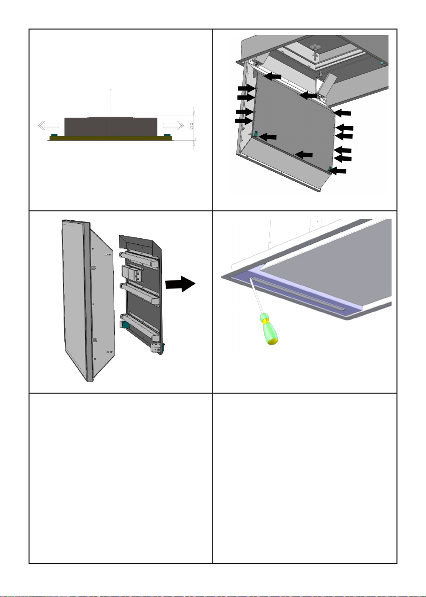
PANELS OPENING
In CE1500, CE1100, CE900 models it is pos-
sible to open the steel panels, which cover
the grease lters, by slightly pulling on a side
of the panel itself, as shown in Fig. 3.
In CE1105 model, to open the panels you
need to push the appropriate hooks placed
on the sides of the panel , as shown in Fig. 11
and then rotating the panel downwards.
To achieve the complete opening of panels,
you need to release the safety chains, by
using the appropriate spring catches.