Caple 1MINCH6 User manual

INTEGRATED EXTRACTOR
Inst uction Manual
Model No: 1MINCH6&2MINCH6

▇
▇▇
▇ TABLE OF CONTENTS
Contents
1.
Extraction Without Intrusion P1~3
2.
Safety & Cleaning P4~5
3.
lternative Methods Of Extraction P6
4.
Operation P7
5.
Fitting Charcoal Filter / Bulb Replacement P8
6.
Electrical Connections P9
7.
Not Working Properly P12
8.
Technical Data P13
The extractor is designed to give you the option to extract air by the
outside and away (via exterior wall), or to re-circulate air through
designed filters to minimize odors, steam and condensation. For internal
recycling the following is required .CF11 Charcoal Filter .Contact 01
4505327 To order
The choice is yours to decide at installation, and both systems are
explained in this booklet.
We recommend that you read this booklet from cover to cover before
attempting to install or operate the extractor
Installation
THESE INSTRUCTION MUST BE STRICTLY ADHERED TO, FAILURE
TO COMPLY COULD RESULT IN OVERHEATING AND SERIOUS
DAMAGE TO YOUR APPLIANCE
To secure the product to the wall you must initially remove the
grille/anti-grease filters. This is achieved by opening the front panel and
pushing the two catches ( ) upwards which will then release the grille.
P1
Ext action Without Int usion

Once the grill has been removed, The front door panel should also be
removed.
Open the front panel and remove the two screws (B) as illustrated above.
Press the tab (C) down and remove the front panel from its guides
Secure brackets(D) onto the top of the extractor using the fitting
screws and washer (E).Check that adjustment screw (F) is fitted.
Note: Note some units may have bracket fitted.
Ensuring there is a minimum distance if 65cm between the bottom of the
extractor and hob surface. Then fix the two mounting brackets (G) to the
rear wall.
Once the two mounting brackets are in position hook the extractor
mounting bracket (D) onto the wall mounting bracket
Some adjustment is provided within the brackets. For forward and
backward adjustment use screw (E) and for height alignment adjusts
screws (F).
Once the adjustment is complete fully tighten all screws.
If after installation there is a gap between the rear wall and the extractor
a spacer is provided. This can be fixed to the rear of the extractor and
cut to accommodate the gap.
IMPORTANT NOTE: fter the extractor has been positioned correctly
the extractor must be fixed to the adjacent through the fixing holes in the
sides of the extractor.
ll that remains is to fix the front wooden door panel to the extractor by
using the diagram below fix the front panel
Ext action Without Int usion Cont..
Ext acto Without Int usion cont..
P2
P3

Before you think about fixing give care consideration to the power
connection. It is vital that the supply cable should be well shielded from
your grill, hob or oven. If it isn’t, heat from any one of these sources may
damage the cable insulation and give rise to a fire risk. Under no
circumstances should the exposed power supply cable come within
70cm of a direct source of heat, ideally it should be channeled into the
wall, well out of harm’s way.
In order to protect your appliance and minimize the risk of fire, don’t
barbecue food directly under the extractor. Similarly, do not prepare
flambé dishes immediately off the flame. Your extractor is designed to
draw gases up and away from your hob. This means that exposed
flames may behave unpredictably in the vicinity of the appliance while it
is switch on. When frying take particular care to prevent the oil from
catching fire and never leave unattended.
IMPORT NT: Before attempting any cleaning or maintenance, ensure
your extractor is disconnected from the power source.
GENER L CLE NING: Regular and thorough maintains guarantee will
provide long lasting operation.
Wipe the external surface of the appliance regularly using warm and a
mild detergent, never use products containing abrasive
Particular care must be paid to the grease filtering panels which must be
periodically cleaned in relation to use (at least once every two months)
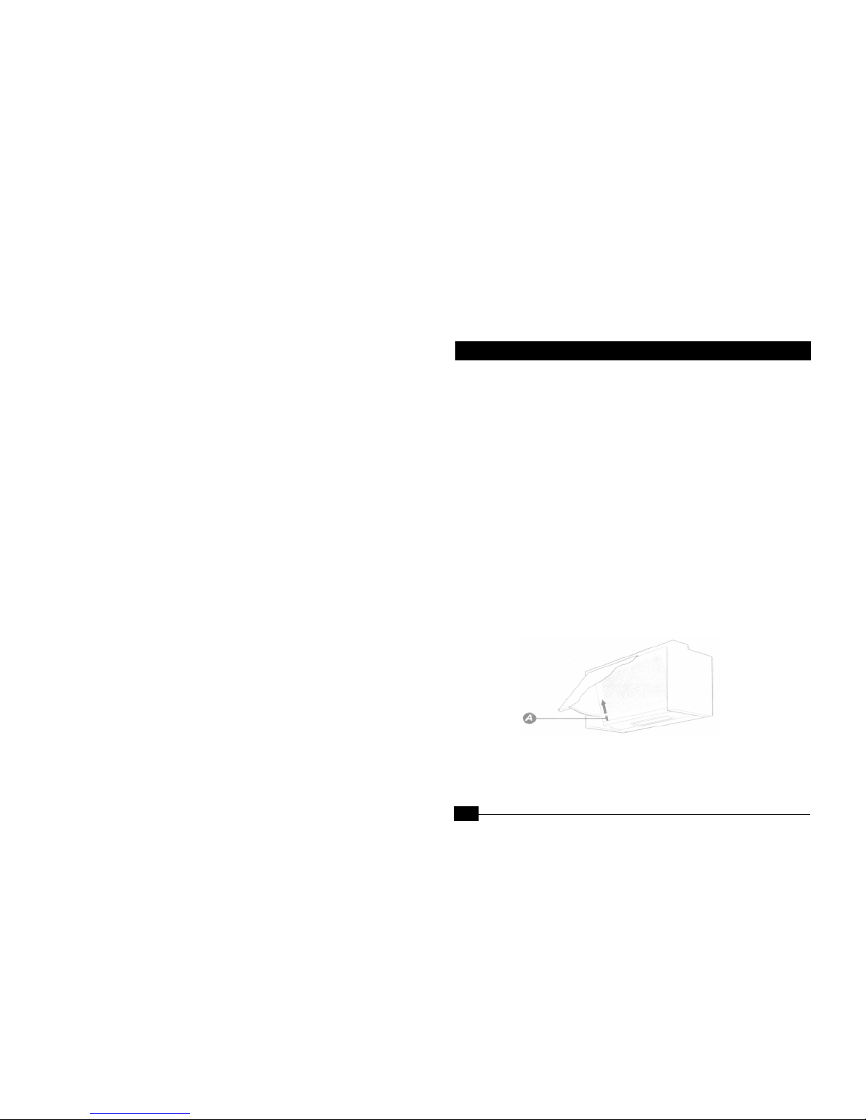
1. Ext action Via Ducting (fig.1)
The very best method of cleaning the kitchen of unwanted odors is
by connecting the appliance to an exhaust duct and venting to the
outside atmosphere via exterior wall (suitable ducting kits may be
purchased from the store where you buy your extractor.) Ducting
your extractor negates the need for charcoal filters.(Fig.1)
Remember: Before drilling or chiseling the wall, check for the pipes and
power cables.
1. Ensure the ducting tube is kept as short as possible and
with minimum of bends to permit the most smooth airflow.
(Maximum length 3M)
Cleaning
P
5
Elect ical Safety
P
4
Fo You Safety
Cleaning
Alte native Methods Of
Ext acto

2. Ducted air must not be discharged into a flue which is used for
exhausting fumes from appliances supplied with energy other than
electricity.
3. Ensure the requirement of the local authorities are adhered to
concerning the discharged of exhaust air.
4. Ensure adequate room ventilation is provided when the extractor is
used in the same room as appliances supplied with energy other
than electricity.
5. Never duct into a hot air flow such as a central heating dust.
We strongly advise that all exterior outlets be fitted with a non etu n
valve of louve ed slotting.
2. The Re-ci culation Mode (Fig.2)
When there is no easy access to an outside wall, the extractor can
easily be adapted to clean air polluted by cooking smells, by using a
charcoal filter which can be purchased from the store where you buy
your extractor. Remember the re-circulation mode can not be used
without a charcoal.
The Cha coal Filte
Filters do have a limited life. We advise you to change it when there is a
noticeable drop in performance. The intervals between changing the
filter will depend entirely upon the amount of cooking you do. But on
average they will last about 4 months.
The G ease Filte
The grease filter requires cleaning every 3 months. If the mat is a
metallic mater it can be cleaned in a dishwasher or washed with a
neutral detergent.
IMPORT NT: You should never attempt to use the extractor without
the grease filter as grease build-up could prevent the motor working
properly. If either filter is not supplied pull out the plug before
changing the filters.
Ope ation You Ext acto
The motor will automatically operate by opening and closing the
front door panel as long as the switch is set accordingly. The
extractor fan has three speed settings for light, medium or heavy
extraction of cooking vapors. The different levels of extraction are
number 1 ,2&3 and can be recognized by the changes in noise level
of the extractor fan when operating.
To switch on the light simply move the switch to position 1.
NOTE: The light is not effected by opening o closing the f ont
panel.
Alte native Methods Of
Ext acto
P
6
Alte native Methods Of
Ext acto
P
7

Bulb Replacement
To replace a bulb simply remove the grill and unscrew the bulb. Replace
with one of the identical type.
Note: The bulb is not cove ed by the gua antee.
Always switch off the elect icity supply p io to changing the bulb.
IMPORT NT: ENSURE TH T THE ELECTRICITY SUPPLY IS
SWITCHED OFF BEFORE CONNECTING.
Your appliance must be connected to fix wiring via the use of a
double pole switched fused spur outlet with at least 3 mm contact
separation, and preferably with a pilot lamp. (See technical data
for fuse rating). We strongly recommend the appliance is
connected by a qualified electrician
NOTE: The terminology “DOUBLE POLE” means that both the
live and neutral supplies are switched and disconnected at the
same time.
The terminations labeled SUPPLY are for the connection for the
internal house wiring and the terminations labeled LO D are for
connection for the appliances.
P
8
Elect ical Connections
P
9
Alte native Methods Of
Ext acto

Impo tant:
The wires in this mains lead are colored in accordance with the following
code:
Blue Neutral
Brown Live
s the colors of the wires in the mains lead of this appliance may
correspond with the colors markings identifying the terminals in your spur
box, proceed as follow:
The wire which is colored blue must be connected to the terminal which is
marked with the letter “N” or colored black. The wire which is colored brown
must be connected to the terminal which is marked with the Letter ‘L’ or
colored red.
WARNING
This appliance has such technical particulars that it belongs to Class 2
insulation and therefore neither wire should be connected to the terminal
marked with the letter E or by the earth symbol.
Light bulb doesn’t come on
replacement is probably necessary, But check first that the bult
is firmly screwed in to its holder. If the filament is broken,
remember that the light bulbs are not covered by our guarantee.
Remember to disconnect power supply before removing the bulb.
Moto is on but fan doesn’t seem to be as efficient as usual
Check grease filter. If it hasn’t been cleaned recently, It might be
clogged with grease. If filter is relatively clean, check charcoal
filters. If this hasn’t been replaced for more than six months.
Remove and replace a new one. s charcoal filters is just the
same way as the grease filter, thereby reducing the efficiency of
both the fan and the filter itself.
Wo ks no mally but cooking smells linge
If you’re using the unit in re-circulation mode, change charcoal
filter. It is obviously past its prime.
Cont ols fail to switch moto no
Check plug, socket and fuse. If these are in order and fault
persists, it could be that an accumulation of grease has impaired
the efficiency of the switch mechanism. Try rapidly moving switch
Elect ical Connections
Not wo king P ope ly ?
P
10
P
11

on and off several times in succession to clear grease deposit. If
fault continues, call service agent.
Appliance does not wo k at all
Check your extractor is switched on at the mains. Next, check out for an
unexpected power strike by switching on adjacent lights etc.
Still not wo king? Call the se vice agent
If, having consulted the above diagnostic chart you are still unable to
remedy the situation, please call Service Call 0870 2411 142..
Single Motor Model
Voltage 220V~240V / 50Hz
Rotation method Single Motor
Rated motor input power 120W
Illumination
≤
25W
Rated input power 145W
Suction power 210m3/h
Noise
≤
61dB
Outlet diameter 120mm
Twin Motor Model
Voltage 220V~240V / 50Hz
Rotation method Single Motor
Rated motor input power 120W x 2
Illumination
≤
25W x 2
Rated input power 290W
Suction power 270 m3/h
Noise
≤
65dB
Outlet diameter 120mm
Not Wo king P ope ly ?
Technical Data
P
13
P
12
This manual suits for next models
1
Other Caple Ventilation Hood manuals
Popular Ventilation Hood manuals by other brands

Artusi
Artusi ASO601RX Operation manual

Zephyr
Zephyr Cypress AK7836CS Use, care and installation guide

Faber
Faber Jewel JEWL2430 Dimensions and installation

Bosch
Bosch DHU665EL Operating and installation instructions

Scheppach
Scheppach DC100 Translation of original instruction manual

Aroua
Aroua Vortix installation instructions