- 20 -
Pull handle B as shown in Fig.6.
MODEL 2
Open panel Cas shown in Fig.5.
Pull handle Bas shown in Fig.6.
If the appliance has a lid, remove it by removing the 4
screws Bas shown in Fig.9A.
• WALL FIXING
Mark the position of the lower side of the hood on the
wall (Fig.2A). Maintain the minimum distance required
from the hob as shown in Fig.2B.
- Position the fixing template on the wall, making sure
that the line coincides with the line previously made on
the wall.
- Mark the fixing holes and cut them into the material
(Fig.3).
- Fix the 2top screws Kand screw anchors (Fig.3),
without tightening them completely.
- Place the appliance against the wall, align it in horizontal
position and tighten screws K(Fig.7).
- Once the adjustment has been completed, fix the hood
using the 2screws C(Fig.8).
- When carrying out the fixing operations, use only screws
and screw anchors suited to the type of wall (e.g.
reinforced concrete, plasterboard etc.).
- If the screws and screw anchors are supplied with the
appliance, make sure that they are suited to the type of
wall to which the hood must be fixed.
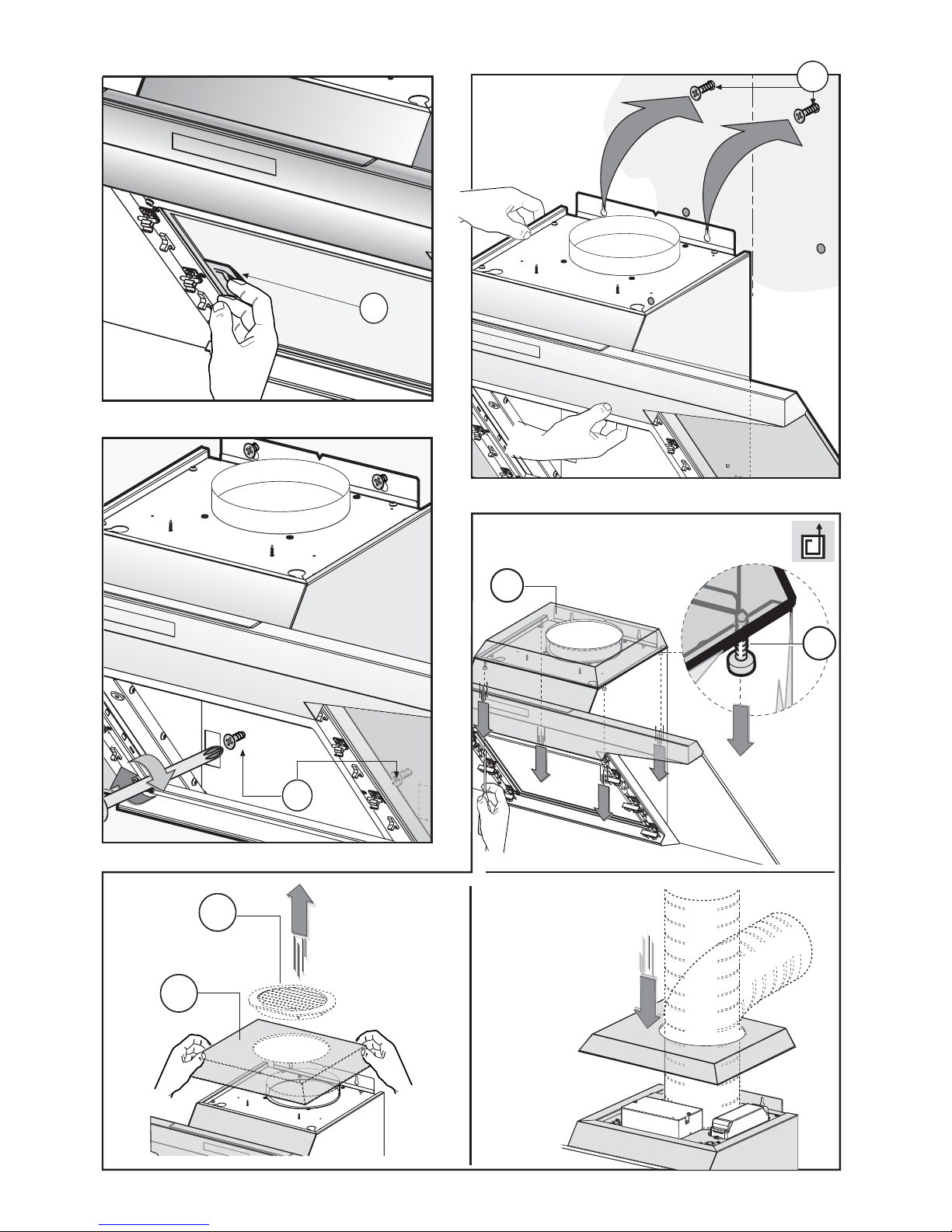
• INSTALLATION OF MODELS WITHOUT DECORATIVE
DUCTS
EXTRACTOR HOOD
- Remove the 4screws Bas shown in (Fig.9A).
- Remove both grid Eon the air outlet hole and lid Mas
shown in (Fig.9B).
- Connect the hood to the flexible hose (not supplied)
and the hose to the air exhaust hole previously prepared
(Fig.9C).
- Fix the lid once again by using the 4screws previously
removed in (Fig.9A).
• OPTIONAL ACCESSORIES
This model may have decorative ducts as optional
accessories - ask your retailer for information.
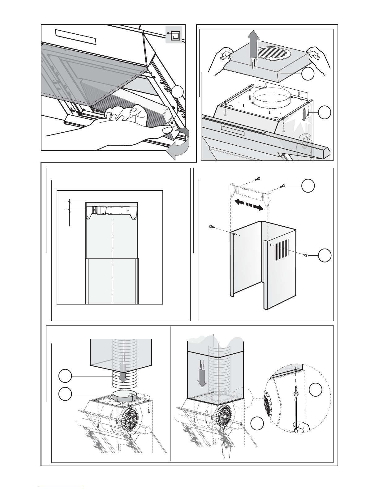
Before fixing the decorative ducts, remove both the 4
screws Band lid M, as shown in (Fig.10A-B).
A sound-absorbing kit is also available (to be ordered as
an OPTIONAL accessory) in order to increase the
quietness level of the hood. The sound-absorbing layer
must be applied to the back of the decorative panel. For
fixing operations, refer to the instructions supplied with
the kit.
• INSTALLATION OF MODELS WITH DECORATIVE
DUCTS
Make sure the electrical power supply is within the
measurements of the decorative connector.
Adjust the width of the support bracket of the top
connector (Fig.11C). Then fix it to the ceiling so that it is
on the same axis as the hood using screws A(Fig.11C)
adhering to the distance from the ceiling shown in
(Fig.11B). Connect flange Cto the air exhaust hole using
flexible hose L (Fig.11D).
Slide the top duct into the bottom duct. Fix the bottom
duct to the hood using screws B (supplied) (Fig.11E).
Pull out the top duct as far as the bracket and fix it using
screws F(Fig.11C).
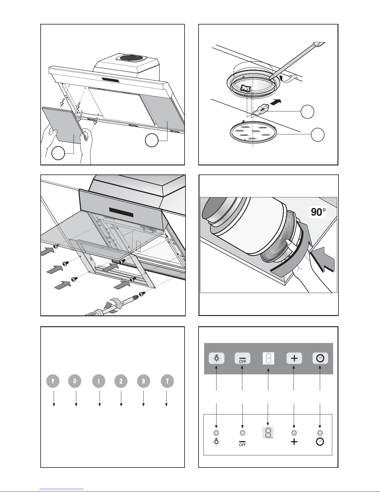
• FILTER HOOD
Please note:
The filters should be ordered as accessories from your
retailer.
We offer 2 different types of kit which can be used to
transform the EXTRACTOR hood into a FILTER hood,
in accordance with the type of appliance model
purchased. One kit contains extractable filters (fig. 10)
and the other contains circular filters (fig. 15).
1- If you find a bracket (such as the one indicated in fig.
14) included in the product packaging, this should be
fixed to the hood using the 6screws supplied.
To replace the active carbon filters pull lever Boutwards
as shown in (Fig.10).
2- If your product is not supplied with a bracket, this
means that the active carbon filter is a circular version
(fig. 15).
The filters should be fitted to the extraction assembly
inside the hood, by centring them and rotating them 90
degrees, until they click into place (Fig. 15).
USE AND MAINTENANCE
•It is recommended to operate the appliance prior to
cooking.
It is recommended to leave the appliance in operation
for 15 minutes after cooking is terminated in order to
completely eliminate cooking vapours and odours.
The proper function of the cooker hood is conditioned
by the regularity of the maintenance operations, in par-
ticular, the active carbon filter.
•The anti-grease filters capture the grease particles
suspended in the air, and are therefore subject to clog-
ging according to the frequency of the use of the appli-
ance.
In order to prevent fire hazard, it is recommendable to
clean the filter at a maximum of 2 months by carrying
out the following instructions:
- Remove the filters from the cooker hood and wash them
in a solution of water and neutral liquid detergent, leaving
to soak.
- Rinse thoroughly with warm water and leave to dry.
- The filters may also be washed in the dishwasher.
The aluminium panels may alter in colour after several
washes. This is not cause for customer complaint nor
replacement of panels.
•The active carbon filters purify the air that is replaced
in the environment. The filters are not washable nor re-
useable and must be replaced at maximum every four
months.The saturation of the active carbon filter depends
on the frequency of use of the appliance, by the type of
cooking and the regularity of cleaning the anti-grease
filters.
•Clean the fan and other surfaces of the cooker hood
regularly using a cloth moistened with denatured alcohol
or non abrasive liquid detergent.