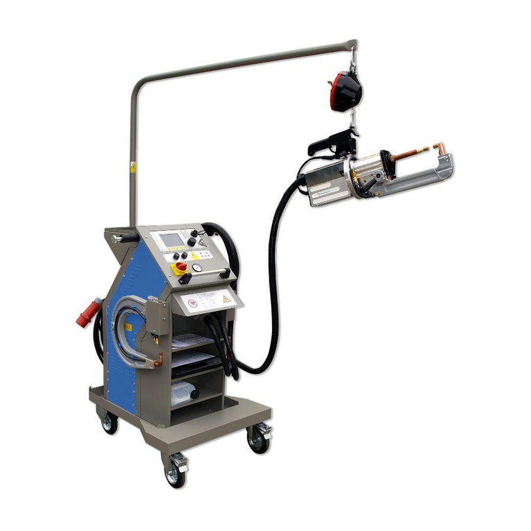
Car-O-Liner CTR12000 User manual

(41644, rev 2) 2012-10, EN
CTR12000
Part 2 - Welding menus and settings
Instruction Manual
(ORIGINAL)

Car-O-Liner Group AB CTR12000
241644, EN - rev. 2, 2012-09
Foreword
The Spot Welder CTR12000 is used by body shops
to duplicate the welding procedure used by the car
manufacturers. All other use of the equipment, or
use that is contrary to the instructions in this manu-
al, can cause personal injury and/or machine dam-
age. Pictures in this manual, where nothing else is
mentioned, and the term “the welder” concerns all
welders.
Car-O-Liner AB can in no way be held responsible
for intentional or unintentional damage, and conse-
quent unlimited loss of profit, loss of income, loss
of business opportunity, loss of use or other similar
nuisance, irrespective of how this has arisen, that
originates from incorrect use of this equipment or
its use in a manner not intended.
Warranty
Car-O-Liner AB offers a two-year guarantee from
the date of delivery. This guarantee covers material
defects and assumes normal care and maintenance.
Wearing parts are excluded from these terms of
warranty. The warranty does not cover normal wear
and tear or damage caused by third persons, by
improper handling or by manipulation by third per-
sons. Normal wear and tear, mechanical damage or
defects resulting from improper handling are ex-
pressly excluded from this warranty.
The guarantee assumes that:
The equipment is correctly installed and in-
spected in accordance with current local regula-
tions.
The equipment has not been altered or rebuilt
without approval from Car-O-Liner AB.
Genuine Car-O-Liner AB spare parts are used
in any repairs.
Operation and maintenance has been carried out
according to the instructions in this manual.
All claims on warranty must verify that the fault has
occurred within the guarantee period, plus that the
unit has been used within its operating range as
stated in the specifications. All claims must include
the product type and article number. This data is
stamped on the name plate.
Note
This instruction manual provides advice as well as
instructions for installation, operation, maintenance
and troubleshooting.
IMPORTANT! Read this manual
carefully to become familiar with the proper
operation of the welder. Do not neglect to
do this as improper handling may result in
personal injury and damage to the
equipment.
The drawings in this manual are intended only to be
illustrative and do not necessarily show the design
of the equipment available on the market at any
given time. The equipment is intended for use in
accordance with current trade practice and
appropriate safety regulations. The equipment
illustrated in the manual may be changed without
prior notice.
The contents in this publication can be changed
without prior notice.
This publication contains information that is
protected by copyright laws. No part of this
publication may be reproduced, stored in a system
for information retrieval or be transmitted in any
form, in any manner, without Car-O-Liner AB’s
written consent.
Copyright © Car-O-Liner AB, 2009
CTR12000 Car-O-Liner Group AB
41644, EN - rev. 2, 2012-09 3
Conformity with directives and standards
The CTR12000 is manufactured by Car-O-Liner AB, which is an ISO 9001:2008 and ISO 14001:2004
accredited organisation.
Below an example of how the EC Declaration of Conformity for the CTR12000 is outlined.
A signed and dated copy of the EC Declaration of Conformity, including serial number, is included in
the documentation for the CTR12000. Please contact your distributor if you need a new copy of the
Declaration of Conformity.

Car-O-Liner Group AB CTR12000
441644, EN - rev. 2, 2012-09
Contents
1
Operation.........................................................................5
1.1General .................................................................................................5
1.1.1Display (1)..............................................................................5
1.1.2Key-operated switch (2).........................................................6
1.1.3Soft keys (3)...........................................................................6
1.1.4Rotary encoder (4).................................................................6
1.1.5LED indicators (5-10).............................................................6
1.1.6USB- Device (11)...................................................................7
1.1.7LED indicators (12-15) / Reset button Q ...............................7
1.1.8Selector switch for “Welding power“ I/kA (18) .......................8
1.1.9Selector switch “Time“ t/s (19)...............................................9
2
Welding menus..............................................................10
2.1General ...............................................................................................10
2.2Starting the welding machine..............................................................11
2.3Operating mode “AUTO“ (Running mode)..........................................11
2.4Operating mode “EDIT“ (Modification mode)......................................11
2.5Operating mode “Expert“ ....................................................................11
3
Welding processes .......................................................13
3.1Fully automatic: VISION / VISION ED COAT .....................................13
3.2Semi automatic: ELMA-QS .................................................................22
3.2.1Pre Spot Operation program ...............................................26
3.2.2Optional settings..................................................................27
3.3Manual: STANDARD (conventional resistance spot welding) ............28
3.3.1Using edge welding caps.....................................................29
3.4Multi-function welding gun (optional tool): SINGLE ............................30
3.5Special automaker programs ..............................................................32
3.6Further adjustments ............................................................................34
3.6.1Description of settings in the "ELMA QS" mode..................34
3.6.2Welding process segments in ELMA-QS mode ..................35
3.6.3Welding process segments in the "VISION" mode..............35
3.6.4Editing synergy characteristics in the "ELMA QS" mode ....36
Definition of “welding power characteristics“ ......................................36
3.6.5Editing synergy characteristics in the "VISION" mode
Definition of “welding power characteristics" ......................................39
3.7Options................................................................................................40
3.7.1General ................................................................................40
3.7.2Working with “Jobs” .............................................................41
3.8USB- Drive ..........................................................................................44
3.9Welding program management...........................................................45
3.10Machine shut-down.............................................................................48
4
Troubleshooting............................................................49

CTR12000 Car-O-Liner Group AB
41644, EN - rev. 2, 2012-09 5
1 Operation
1.1 General
Your welding machine offers multiple functions and a large range of differ-
ent settings though the number of control elements is quite reduced. This
“economy of switches“ results from the high-tech microprocessor control
system.
The most important control element – the rotary encoder – is located on the
power source’s control panel. Together with the large, easy-to-read display,
this switch offers to the user unique operating convenience: You may easily
switch between different programs for different – and also very demanding –
welding tasks and with the same convenience; you may also adapt the pro-
grammed combination of parameters to special requirements.
1.1.1 Display (1)
The machine has a liquid crystal display (LCD). For detailed information on
the different screens, such as for the different welding programs, see chapter
2 Welding menus.
5
–
10. LED indicators
1. Display
3. Soft keys
11. USB Device
12-15. LED indicators /
Reset button Q (also
being incorporated in the
welding tong’s handle)
18. Power I/kA
potentiometer
19. Time t/s
potentiometer
4. Rotar
y
encode
r
2. Key operated switch
AUTO/EDIT

Car-O-Liner Group AB CTR12000
641644, EN - rev. 2, 2012-09
1.1.2 Key-operated switch (2)
The key lock switch allows access and selection of the operating modes
“AUTO“(Automatic operation) and “EDIT“(Edit//Program). The standard
mode for welding operation is “AUTO”.
Service menus are only accessible while the key lock switch is in position
“EDIT“. Pull out the key to prevent any manipulation by unauthorized per-
sons and keep it in a safe and accessible place.
1.1.3 Soft keys (3)
The soft keys (membrane switches) are used for selecting the functions that
are indicated in the lower display bar – exactly above the corresponding soft
key. You can also use the rotary encoder to call these functions.
1.1.4 Rotary encoder (4)
The rotary encoder can be used to select all the welding functions being
available. For this purpose, turn the rotary encoder until the desired function
is displayed in a gray field. Then press the switch for activating the corre-
sponding function or the selection menu (windows based).
Depending on the menu, the ESCAPE button (at the bottom right of the dis-
play) or the term “ESCAPE” appears. Select the ESCAPE button or the
ESCAPE function, if you do not wish to make a choice. All the settings
made before in the menu concerned are cancelled and the original values are
maintained.
1.1.5 LED indicators (5-10)
(5) YELLOW: Indicates that the welder is ready for operation
(6) GREEN: Indicates that welding operation is being performed
(7) RED: Indicates pending malfunction

CTR12000 Car-O-Liner Group AB
41644, EN - rev. 2, 2012-09 7
(8) QS-RED: Indicates that spot weld is faulty or not weldable, or faulty
current tong calibration or that the tong used is not suitable.
(9) QS-YELLOW: Indicates heating phase for preparing the spot weld or
warning limit for current tong calibration.
(10) QS-GREEN: Indicates that spot weld and/or current tong calibration
has been okay. Indicates alarm limit or current tong calibration error, if the
LED indicator QS-Yellow and/or QS-Red lights up, too.
QS-RED/YELLOW: Indicates that the spot weld is faulty, that there is a
problem of insulation, and that the welding operation has been interrupted
during the preheating phase.
1.1.6 USB- Device (11)
The USB- Device offers most simple data transfer between operator and ma-
chine. The data is downloaded on or uploaded from a USB- Stick.
See chapter 3.8 “USB drive” for information on use.
Additional control elements are located on the lower control panel of the
power source.
1.1.7 LED indicators (12-15) / Reset button Q
NOTE! Also being incorporated in the handle of the welding tong.
12
13
14
15

Car-O-Liner Group AB CTR12000
841644, EN - rev. 2, 2012-09
LED for “Tool” (12)
Indicates incorrect calibration of the current tong or that the tong is not suit-
able, or – the LED’s Tool and Electrode being flashing – that calibration of
the current tong is necessary
LED for “Electrode” (13)
Indicates that electrodes need to be checked (limit of the spot counter has
been reached). With flashing LED: see above.
LED for “Fuse” (14)
Indicates that the start of the welding operation has been suppressed during
the recovery time of the primary fuse.
LED for “Spot welding error” (15)
Indicates faulty spot weld, welding could not perform because of full or part
insulation or welding time outside the QS limits.
Reset button Q
For error acknowledgement.
1.1.8 Selector switch for “Welding power“ I/kA (18)
The potentiometer “Power” I/kA has two functions
1. In Manual STANDARD welding mode (conventional spot
welding), the welding current is adjusted by means of the
potentiometer “Power” l/kA on a scale in kA.
2. While in the Semi Automatic ELMA-QS mode (ELMA spot
welding with QS supervision), the potentiometer “Power“ is used
to preset the total material thickness on the large display
(independent of the scale) with all the relevant welding parameters
being adjusted automatically in the background (synergy table).

CTR12000 Car-O-Liner Group AB
41644, EN - rev. 2, 2012-09 9
1.1.9 Selector switch “Time“ t/s (19)
While in the STANDARD welding mode (conventional spot welding), this
potentiometer is used to preset the welding time on a scale in t/s. For all the
other operating modes, this potentiometer has no function.

Car-O-Liner Group AB CTR12000
10 41644, EN - rev. 2, 2012-09
2 Welding menus
2.1 General
Basic screen
Programs, selection menus and parameters are selected from and displayed
on the basic screen. Display button (F5) is used to indicate and display pro-
grams, set points and actual values.
Display screen
The example above shows the following setting:
Welding task: CHECK-EL, Welding process:VISION, welding program:
BASIC, C-gun: C 80 arm, electrode CAP: 13 mm and welding operation:
AUTOMATIC.
The integrated welding programs that are stored in the physical welding da-
tabase have write protection. They can however be used to create personal-
ized welding program (see 3.7) , while being in the EDIT mode.
Additionally, you may create personalized welding programs to be saved as
follows:
Up to 99 synergic user programs: X01 - X99
Up to 99 JOBS: J01 - J99 (see 2.10.2)
You may modify or overwrite synergic user programs (X01 - X99) as often
as you like.
Optional
program
VAS 6755.
Optional
program
BMW. Choose with soft key F5.

CTR12000 Car-O-Liner Group AB
41644, EN - rev. 2, 2012-09 11
Attention: While on the screen „Synergic user programs“, the machine al-
ways offers to the user the program X01 first. Save your newly written pro-
gram under another name (e.g. X02, X03 ... or J01, J02…) to prevent other
priory created programs from being overwritten.
2.2 Starting the welding machine
The welding machine has been properly set up and connected to the mains.
Now switch on the machine using the main switch (see chapter 5: “Start-up”
in the first part of the operating manual).
After the machine has been switched on, it takes about 5 – 10 seconds until
the welding control system has performed a self-test. During this time, the
Car-O-Liner logo is displayed on the screen. After that, the selected synergic
welding program or the last program used is displayed on the screen.
2.3 Operating mode “AUTO“ (Running mode)
The “AUTO” mode allows welding programs to be selected via synergic se-
lection parameters (welding process, task, selection, and tong).
This operating mode does not allow program modification but the selection
of invariable programs or, while in the ELMA-QS mode, to adapt the total
plate thickness and thus the synergic background parameters to the welding
task by means of the potentiometer “Power” I/kA. The plate thickness is ad-
justed independently of the potentiometer dial and is displayed in mm on the
large display screen.
2.4 Operating mode “EDIT“ (Modification mode)
For welding program modification, the key has to be put into the key lock
switch and turned to “EDIT”. Only then you have access to variable parame-
ters that are explained in Optional settings, page 27.
2.5 Operating mode “Expert“
This mode allows extended-range modification of the basic machine set-
tings. However, improper handling may impair welding results. Therefore
access is protected by a password.

Car-O-Liner Group AB CTR12000
12 41644, EN - rev. 2, 2012-09
If you are interested in the Expert operating mode, please contact your local
Car-O-Liner distributor which will be pleased to offer you instructions and,
if necessary, more detailed information about this mode.

CTR12000 Car-O-Liner Group AB
41644, EN - rev. 2, 2012-09 13
3 Welding processes
Having switched on the spot welder, you have to select and determine the
type of welding process first. You may choose one of the following
processes: VISION, VISION ED coat, ELMAQS, STANDARD, specific
automaker program OPEL and OPEL-VP for Opel. Also available optional
programs like BMW-QS for BMW or VAS 6755 for Volkswagen.
It is also possible to use the SINGLE- mode for the single sided tong.
3.1 Fully automatic: VISION / VISION ED COAT
VISION: Welding on clean grinded surface sheet metal.
VISION ED COAT: Welding on electrolytic dipped sheet metal.
By pressing the gun trigger and closing the tong a complex measuring
system starts its work. It is able to collect the total thickness of the material
which should be welded, and with the start of the current flow it recognises
if there is a normal or high strength steel between the electrode caps, within
some milliseconds. For that the machine controls the welding process fully
automatic without any adjustments.
By selecting the "WELDING" mode, the following display appears on the
screen:
Flashing of the two LED’ s „TOOL“ and „ELECTRODE“ indicates that the
machine has to pass the calibration of the welding tong. The calibration is
used to collect the exact process resistance during the welding process, ad-
justing the right tong tool and to calibrate the pulse- sonar- system of the
welding tong.

Car-O-Liner Group AB CTR12000
14 41644, EN - rev. 2, 2012-09
Before starting with the fully automatic welding process, you have to do the
following adjustment:
1. Choose „CHECK-EL“ in the task menu.
2. Choose the connected tong and electrode arm.
The following adjustments are possible.
3. Choose electrode cap.
A
ttention: C-40 is not used in
VISION/VISION EDcoat mode!
Standard version: VW version: BMW version:

CTR12000 Car-O-Liner Group AB
41644, EN - rev. 2, 2012-09 15
4. Choose the MODE „ AUTOMATIC“
In operation mode AUTOMATIC the EDIT- key should be switched to AU-
TO because otherwise the puls- sonar system which is integrated in the tong,
could not collect the total thickness of the material and the right parameters
that are needed are locked.
If the EDIT- key is on EDIT, an error message (red fault light) would also be
shown, which has to be quitted by the user.
Attention! Always use new or clean electrode caps when making
CHECK-EL!

Car-O-Liner Group AB CTR12000
16 41644, EN - rev. 2, 2012-09
The result of the calibration is displayed with the LED’ s of the QS- “traffic
light” and the LED’ s “tool” and “electrode” in the lower control panel.
If the machine has performed the CHECK-EL successfully change the
adjustment to menu task „ WELDING“
Now the machine is ready to start welding.
By pressing the soft key F5 you change to display mode.

CTR12000 Car-O-Liner Group AB
41644, EN - rev. 2, 2012-09 17
By changing the „ OPERATION MODE“ from AUTOMATIC to MANU-
AL the automatic measuring system to collect the total material thickness is
switched off. Instead you can adjust the thickness of material you want to
weld manually by turning the “Power” potentiometer.
The CTR12000 is equipped with a quality control system (QS), which give a
statement about every single spot during the welding process. The in particu-
lar phases resulting parameter characteristics are evaluated by program seg-
ments and depending on this, engagements are created to lead to a safe quali-
ty result.
Following phases could appear individually:
Total isolation, in such a case an isolation between the metal sheets which
should be welded and lack of a bypass (spot weld nearby or vise grip) could
cause that no welding current is generated at the caps. The machine stops the
process automatically and displays the signal spot error (red), error code 16.
Partwise isolation, the welding current do not flow the direct way from the
electrode through the metal sheets, but a detour. Then a preheating is acti-
vated automatically which heat the metal sheets and through maceration or
evaporation, burns through the glue or varnish rest at the spot area. The term
of that phase the yellow light keeps lighting. If that will not succeed in a pre-
setted time the process will be aborted. The red light signals the error. In the
case of success the yellow light stops lighting and the green light appears.
During "pre pulse" segment the process is leaded by the virtual generator.
The goal is to reach the welding current, which is reached individual in a dif-
ferent time without any disturbance through evaporation with weld spatters.
Normal steel will suffice in some milliseconds, with high strength steel it
could last for up to 300ms. Please pay attention that with high strength steel,
at that phase, up to 50 percent of the inserted energy is transferred, so the
welding time will not extend. For the case that the presetted critical time ex-

Car-O-Liner Group AB CTR12000
18 41644, EN - rev. 2, 2012-09
ceed, the red light signals an error (Error code 3). If the process was success-
ful the green light is shown.
The process is controlled in the welding segment either with the current for
normal steel or with a lower current for high strength steel. The decision cri-
terion has been created in the segment “pre pulse”. The process is not, in op-
position to usual procedures, time- oriented. The energy at the electrode caps
is balanced and compared with the energy- target value in the database. With
the achievement of the target energy within the presetted critical time the
process ends.
During the welding, following signals could appear:
a) green; code 10 (the resistance is between the reference resistance
and the presetted maximum resistance)
b) green after yellow; code 11 (resistance is higher than the
presetted maximum resistance)
If the resistance by reaching the target energy lower than the reference
resistance, there is a bypass on the workpiece and the virtual machine
calculates the seize of the bypass and add the correct energy value.
a) green after yellow; code 12 (energy was added because of a
bypass)
b) green after yellow; code 13 (process ended without adding
energy)
c) green after yellow; code 14 (process ended with adding energy)
The segment post heating stopps the process. The currentflow- and time
are different at normal- and high strength steel.
Status signals ERROR x, CODE y; are displayed in the debugger mode,
af_hv09 ( cell 181 with VM1 ).

CTR12000 Car-O-Liner Group AB
41644, EN - rev. 2, 2012-09 19
Error11 F11‐Check(Resistance‐ZERO)
Error12 F12‐CheckDistance(Position‐Zero)
Error13 F13‐CheckvalueDistanceoutoftolerance
Error14 F14‐Check‐Resistancetoohigh
Error15F15‐Check‐Resistancetoolow
Error16 F16‐Total‐Isolation
Error17 F17‐MeasuredvalueoutofTolerance
Error18 F18‐KeyswitchonEDITSetting
Error19 F19‐Startingenergytoolow
Error20 F20‐Startbuttonnotactivated
Error21 F21‐Testcyclesnotsuccessfull
Error22 F22‐Criticaltimereached
Error23 F23‐Sheetthicknesslower0,1mm
Error24 F24‐NovalidCheckvalues
Error25 F25‐NoIsolationbreakthroughafterPre‐heating
Error26 F26‐120%Applicationofenergyexceeded
Error code list

Car-O-Liner Group AB CTR12000
20 41644, EN - rev. 2, 2012-09
With the oscillograph- plug in, 3 status signals could be displayed after the
process:
a) integrated process resistance during the segment "pre pulse"
(SAutoTX)
b) Averaged process resistsance during the segment welding (SAuto)
b) display status ( Error- code: 1 to 12), ( Success- code: from 10)
The status is displayed in 0,5V steps ( e.g. Error 5=> 2,5V; Code 12=> 6V)
The QS- System was optimised, that after a welding a definite conclusion is
displayed:
Green for a successful action or red for an automatic process abort. A pro-
cess abort is achieved if a given critical time exceeds, that could happen dur-
ing an unusual activity. That could happen if, e.g. the electrodes are posi-
tioned on the edge of the work piece or there is an interruption on the mains.
Such an interruption also could happen if the calibration (CHECK-EL) is
made with dirty electrode caps.
These differences, which could be tolerated and which are lower than with a
usual current/ time control are displayed with a yellow light during the pro-
cess. After the process stops, the yellow light is replaced usually by the
green light, if the CTR12000 control system finish the process successfully.
Intermediate messages, yellow, could appear if, e.g. to breakthrough a part
wise isolation or the resistance characteristic is higher than generally ex-
pected.
Attention! Exceeding of welding time indicates that the calibration was in-
correct. This may occur when copper electrodes are not cleaned. Please clean
the electrode caps at the contact surface. Be careful not to make scratches or
slots! Dirty electrode caps could endanger the calibration and thus the quali-
ty and safety management of the machine.
Attention! The measuring system reach it’s correct accuracy normally when
the electronic components are at it’s operating temperature. Please perform
the CHECK- EL after some minutes after switching on the machine.
Attention! Please be careful by changing the electrode arms. The welding
tongs contain a sensitive measuring system inside which could be damaged
by intrusion of water. It’s important that the solid arm of the X- tong is in the
Other manuals for CTR12000
1
Table of contents
Other Car-O-Liner Welding System manuals

Car-O-Liner
Car-O-Liner CMI 300 Pulse Boost User manual

Car-O-Liner
Car-O-Liner CR510 User manual

Car-O-Liner
Car-O-Liner CM 193 User manual

Car-O-Liner
Car-O-Liner CM Series User manual

Car-O-Liner
Car-O-Liner CTR12000 User manual

Car-O-Liner
Car-O-Liner CTR9 User manual

Car-O-Liner
Car-O-Liner CMI3000 II User manual

Car-O-Liner
Car-O-Liner CR35 User manual

Car-O-Liner
Car-O-Liner CMI 161 User manual