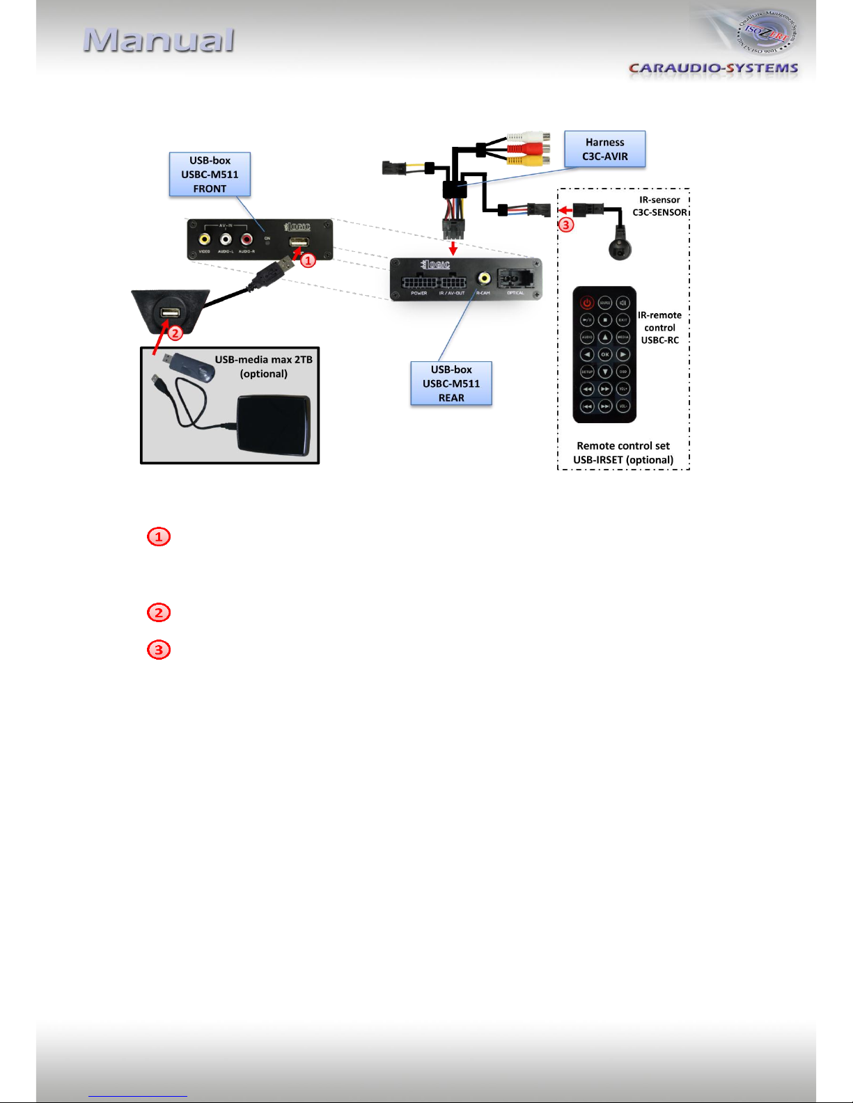
3.3. USB and optional IR-remote control set
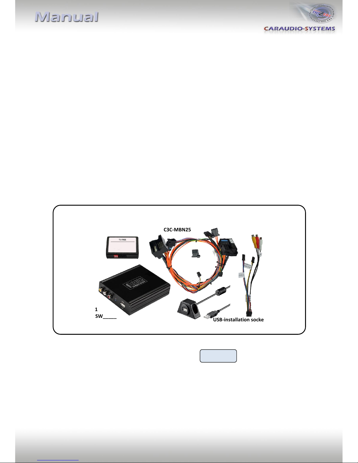
Connect USB-connector of USB-installation socket USBC-EXT to USB-socket of USB-
Box USBC-M511 and install the USBC-EXT socket in a well accessible location, e.g. the
glove-box. Make sure there is enough space to load USB-media.
Installation socket for the connection of USB-media.
The USB-IRSET consists of the external C3C-SENSOR IR-sensor and the USBC-RC IR-
remote control and can be used to control the usbLOGiC’s internal USB functions
additionally to the control through the navigations buttons. Connect the C3C-
SENSOR to the female black/red/blue 3pin AMP connector of harness C3C-AVIR and
locate the sensor in an accessible place.
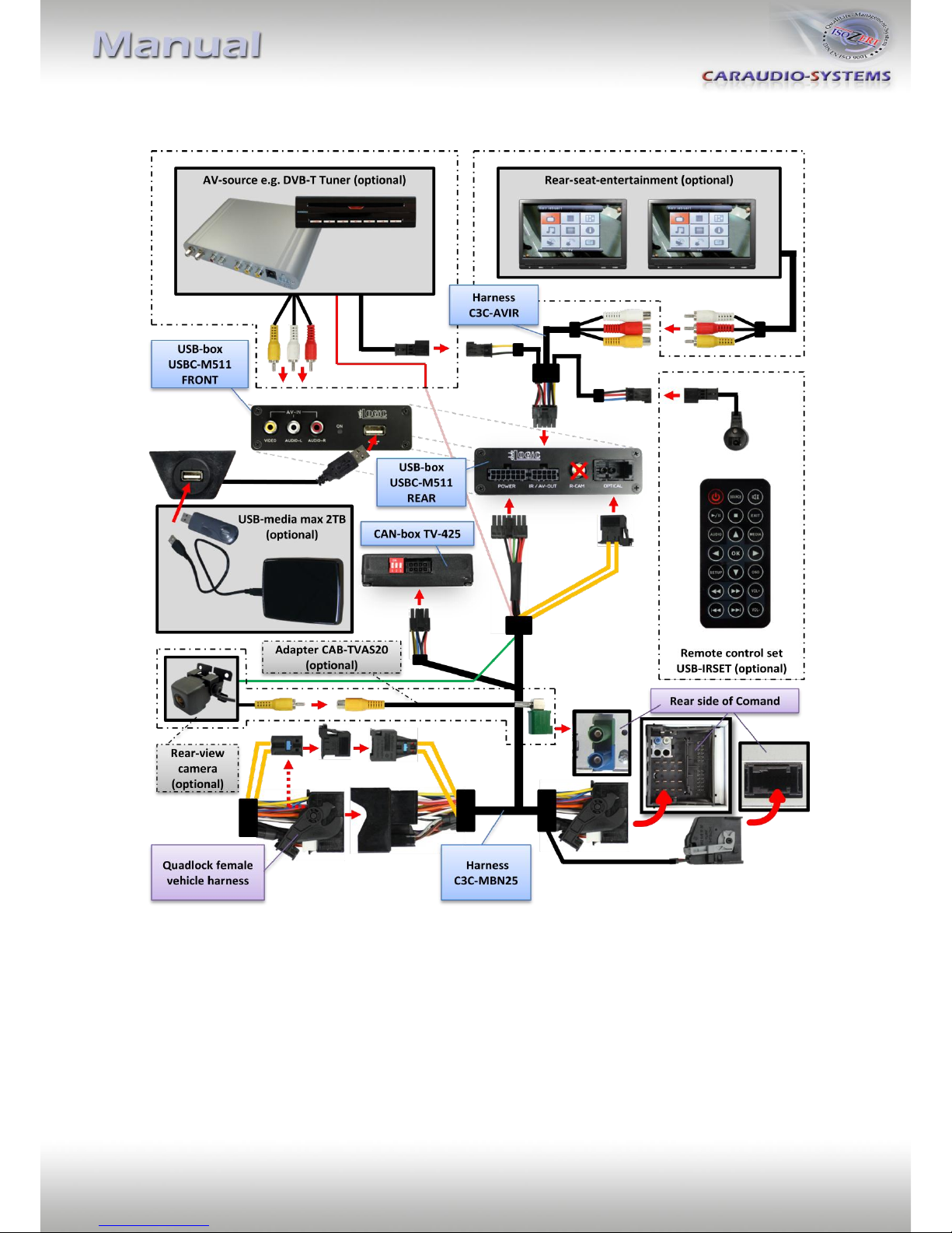
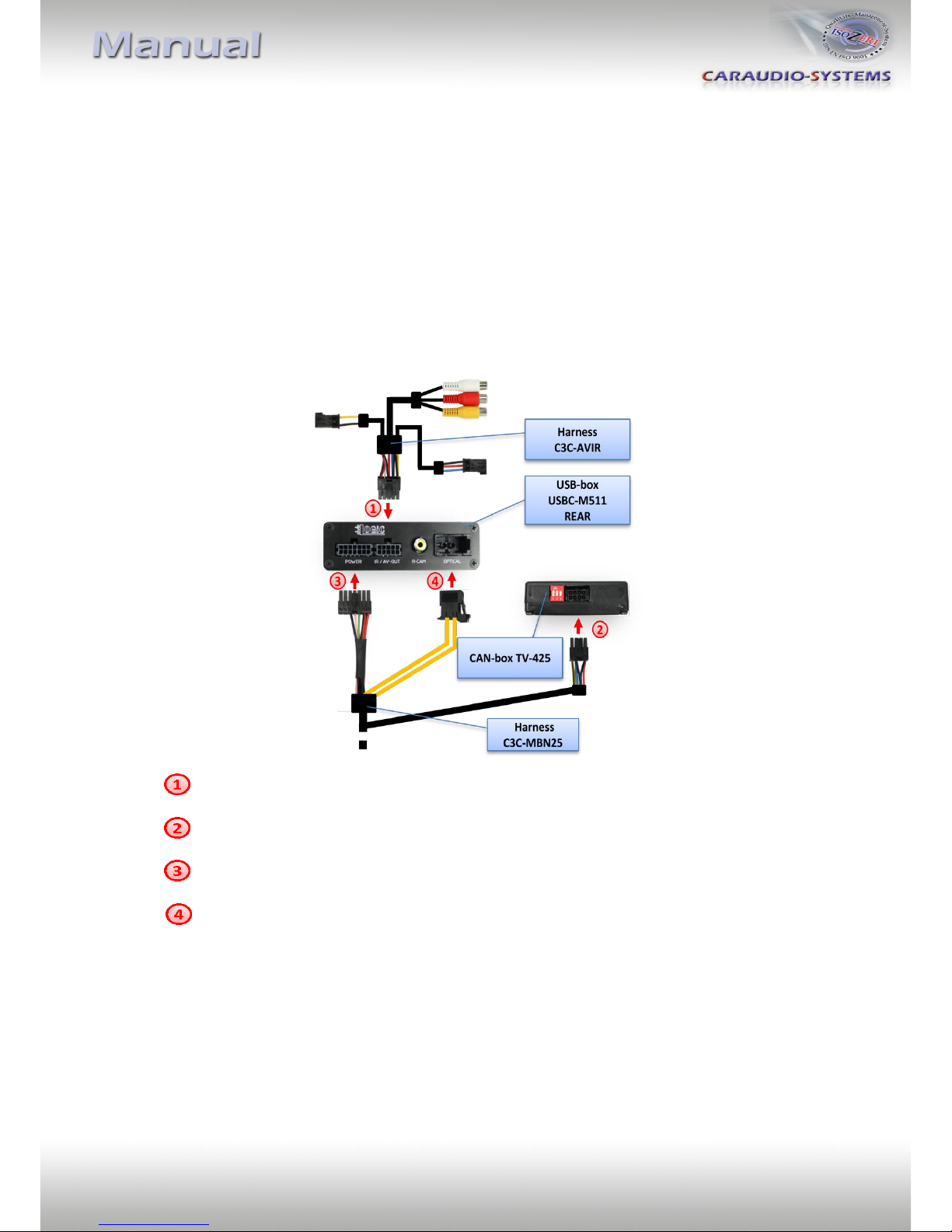
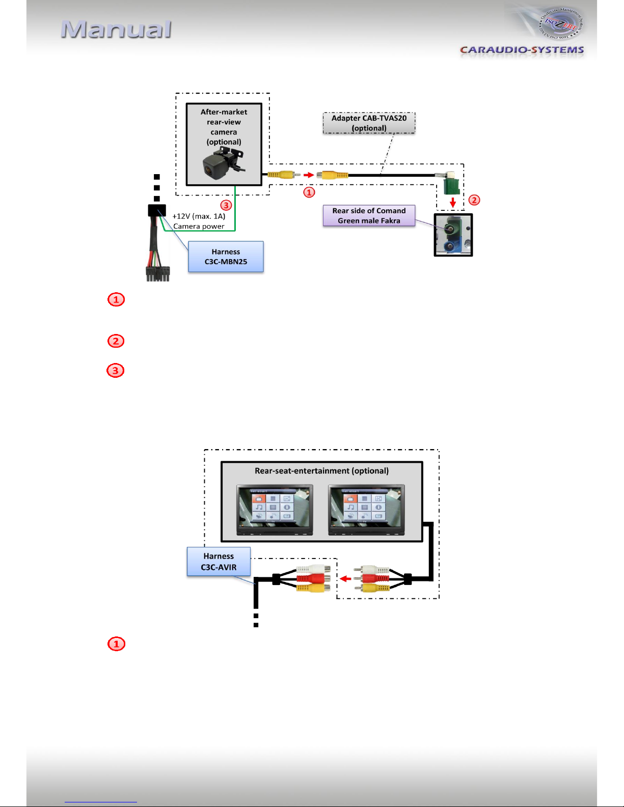
3.4. Connecting peripheral devices
It is possible to connect an after-market AV-source and rear-seat-entertainment to the
usbLOGiC, as well as to code the Comand’s rear-view camera input for an after-market or
factory rear-view camera.
Before final installation of the peripheral devices, we recommend to test-run the usbLOGiC
functions to detect incompatibility of vehicle, navigation, factory accessories or peripheral
devices as soon as possible.