FOR TECHNICAL SUPPORT CALL 1800 658 111
8
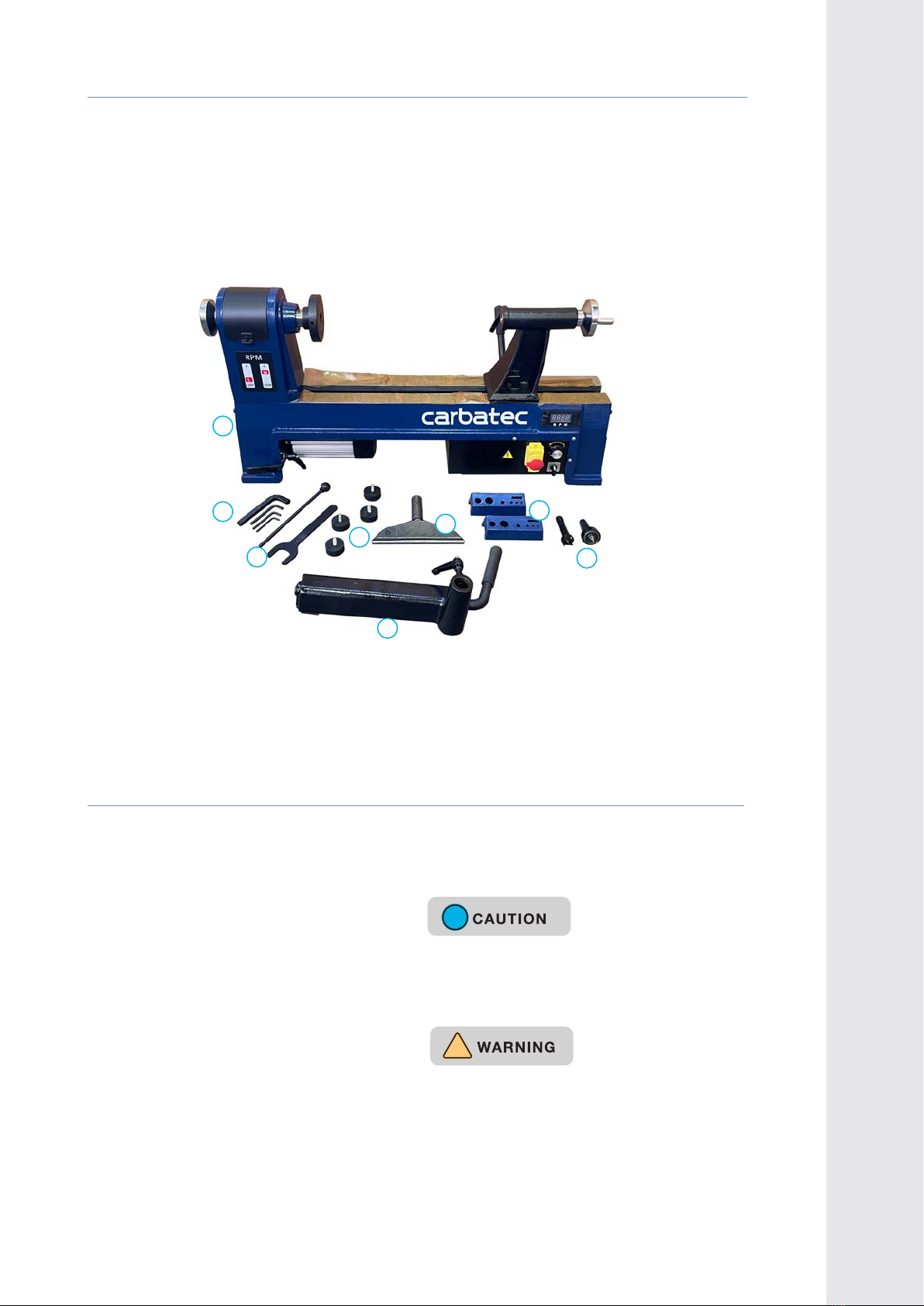
WL-B1420P
11. ALWAYS UNPLUG THE TOOL FROM THE
ELECTRICAL RECEPTACLE
when making adjustments, changing parts or
performing any maintenance.
12. KEEP PROTECTIVE GUARDS IN PLACE AND
IN WORKING ORDER.
13. AVOID ACCIDENTAL STARTING.
that the power switch is in the “OFF” position
before plugging in the power cord to the
electrical receptacle.
14. REMOVE ALL MAINTENANCE TOOLS from
the immediate area prior to turning “ON”
the machine.
15. USE ONLY RECOMMENDED ACCESSORIES.
could cause serious injury to the operator
and cause damage to the tool. If in doubt,
check the instruction manual that comes with
that particular accessory.
16. NEVER LEAVE A RUNNING TOOL
UNATTENDED. Turn the power switch to the
“OFF” position. Do not leave the tool until it
has come to a complete stop.
17. DO NOT STAND ON A TOOL.
could result if the tool tips over, or you
accidentally contact the tool.
18. DO NOT STORE ANYTHING ABOVE OR
NEAR the tool where anyone might try to
stand on the tool to reach it.
19. MAINTAIN YOUR BALANCE. Do not extend
yourself over the tool. Wear oil resistant
debris, grease, and wax.
GENERAL SAFETY
20. MAINTAIN TOOLS WITH CARE. Always
keep tools clean and in good working order.
Keep all blades and tool bits sharp, dress
grinding wheels and change other abrasive
accessories when worn.
21. EACH AND EVERY TIME, CHECK FOR
DAMAGED PARTS PRIOR TO USING THE
TOOL. Carefully check all guards to see that
they operate properly, are not damaged, and
perform their intended functions. Check for
alignment, binding or breaking of moving
parts. A guard or other part that is damaged
should be immediately repaired or replaced.
22. DO NOT OPERATE TOOL WHILE TIRED,
OR UNDER THE INFLUENCE OF DRUGS,
MEDICATION OR ALCOHOL.
23. SECURE ALL WORK.
secure the work piece. This is safer than
attempting to hold the work piece with your
hands.
24. STAY ALERT, WATCH WHAT YOU ARE
DOING, AND USE COMMON SENSE WHEN
OPERATING A POWER TOOL. A moment of
inattention while operating power tools may
result in serious personal injury.
25. USE A PROPER EXTENSION CORD IN GOOD
CONDITION
be avoided where possible. When using an
extension cord, be sure to have a cord heavy
enough to carry the current your product will
Longer run extensions will need heavier
duty extension cords. Only connect your
extension cord or machine to a receptacle
that accepts your plug and never modify your
plug to suit a receptacle.