manuals.online logo
Brands
  1. Home
  2. •
  3. Brands
  4. •
  5. Carbine
  6. •
  7. Lock
  8. •
  9. Carbine CFB-EH User manual

Carbine CFB-EH User manual

Dimensions for lock cutouts,
refer to CFB-D / CFB-HB
installation instructions.
20 + DOOR EDGE
EXTRUSION
THICKNESS
1
64 94 128
Drill 3 x Ø9 holes
Ø14 - 19
DOOR EDGE
EXTRUSION
THICKNESS
1
Item No. Description QTY
1 Drill Template 1
2 Egress Handle 1
3 Mounting Plate 1
4 Left- hand Spindle 1
5 Right- hand Spindle 1
6 Mounting Plate Clip 1
7 Bottom Mounting Screw 1
8 Top Mounting Screw Pin 1
9 Spindle Plate 1
10 Spindle Screw 1
Drill holes through
handle side only
LINE UP WITH SPINDLE
CTR LINE ON LOCK
FRONT FACE
BACKSET
EXTRUSION
THICKNESS
TOP
DRILL
9
SPINDLE
CTR LINE
DRILL
14 to 19
DRILL
9
DRILL
9
1
2
3
4
567 8
910
LINE UP WITH SPINDLE
CTR LINE ON LOCK
FRONT FACE
SPINDLE
CTR LINE
DRILL
14
DRILL
8
DRILL
8
1. EGRESS HANDLE COMPONENT PART LIST
REFERENCE DIMENSIONS FOR EGRESS HANDLE INSTALLATION
The Next Generation in Locking
CFB-EH FLIP BOLT MORTICE LOCK - EGRESS HANDLE
REFERENCE DIMENSIONS
Install Egress Handle using drilling template (next page)
Distributed in Australia by
LOCK AND KEY a division on the
DAVCOR GROUP PTY LTD ABN 95 003 562 598
This product has been manufactured in China
to Lock and Key Company specifications
This product is guaranteed to be free from defects in materials and
workmanship for a period of one (1) year from the date of original
purchase. This warranty is for replacement of product only and Lock
and Key Company does not accept responsibility for any direct or
consequential damage caused by this product or its use. This warranty
does not cover damage that results from faulty installation or usage,
alteration or modification of the product or tarnishing of the finish
including colour change due to weather, salt or chemical. Should this
product not perform satisfactorily in its intended application, return it
to place of purchase for replacement.
LOCK & KEY Phone: 1300 652 692 Web: www.locknkey.com.au Web: www. daveweb.com.au
NOTE
Please dispose of plastic
bags and other packaging
in a thoughtful manner
WARNING
Please keep contents
away from small children.
Suffocation Hazard.
Special Notes:
For lock installation instructions, please refer to installation instructions provided with CFB-D / CFB-HB.
For installation together with CLS-FAB - Flip Bolt Latching Strike, please refer to the installation instructions provided with CLS-FAB.
For installation together with CFB-OCEP - Oval Cylinder Rectangular Escutcheon, please refer to the installation instructions provided with CFB-OCEP.
LINE UP WITH SPINDLE
CTR LINE ON LOCK
FRONT FACE
BACKSET
EXTRUSION
THICKNESS
TOP
DRILL
9
SPINDLE
CTR LINE
DRILL
14
DRILL
9
DRILL
9
LINE UP WITH SPINDLE
CTR LINE ON LOCK
BACKSET
EXTRUSION
THICKNESS
TOP
DRILL
8
2A Insert lock into
door cavity.
ENSURE BOLT IS
EXTENDED.
2B Secure with
2x M4x16mm CSK
Screws (supplied
with lock).
2. DRILLING TEMPLATE INSTRUCTIONS
The Next Generation in Locking
CFB-EH FLIP BOLT MORTICE LOCK - EGRESS HANDLE
2C Insert drilling template
into cutout and against lock
face as shown.
Identify the colour that lines
up (closest) with the door
edge face.
2E Remove the 2x
M4x16mm CSK
Screws and lock
from the door.
2F Drill the following
holes as shown on the
diagram.
2G Preparation for installation of
egress handle furniture and lock
into metal door is now complete.
Continue with egress handle
furniture installation instructions
section 3.
Drill Ø9 hole
Drill Ø14 to 19 hole
Drill Ø9 hole
Drill Ø9 hole
LINE UP WITH SPINDLE
CTR LINE ON LOCK
FRONT FACE
BACKSET
EXTRUSION
THICKNESS
TOP
DRILL
9
SPINDLE
CTR LINE
DRILL
14 to 19
DRILL
9
DRILL
9
2D To determine the correct
backset position, align the
corresponding same coloured line
at the top and bottom, as shown
on the diagram.
Ensure template is straight.
To determine the vertical position
of the template, align the spindle
ctr line with the spindle line on the
lock
Mark drilling holes.
LINE UP WITH SPINDLE
CTR LINE ON LOCK
FRONT FACE
BACKSET
EXTRUSION
THICKNESS
TOP
DRILL
8
SPINDLE
CTR LINE
DRILL
14
DRILL
8
DRILL
8
Spindle
Line
The Next Generation in Locking
CFB-EH FLIP BOLT MORTICE LOCK - EGRESS HANDLE
4A. INSTALLATION OF SPINDLE FOR LEFT-HAND DOOR FURNITURE 4B. INSTALLATION OF SPINDLE FOR RIGHT-HAND DOOR FURNITURE
LEFT-HAND SPINDLE
(SILVER)
4A.A Insert silver left-hand spindle
(two dots) into the hub of handle and
replace the spindle plate and securely
refasten screw.
4A.B Ensure the handle is in the
upright position for installation.
4B.B Ensure the handle is in the
upright position for installation.
4B.A Insert black right-hand spindle
(one dot) into the hub of handle and
replace the spindle plate and securely
refasten screw.
Left-hand
Configuration
(Supplied)
Left-hand 45°
Configuration
RIGHT-HAND SPINDLE
(BLACK)
Right-hand 45°
Configuration
Right-hand
Configuration
Left-hand
Left-hand 45°
Right-hand 45°
Right-hand
3A Remove screw and carefully
pull handle and nylon bush off the
faceplate and rotate handle at
desired configuration as shown on
the diagram.
Spring Position
3C Securely re-tighten handle
retention screw back into handle.
3D Test operation to ensure
change of handing is correct.
3B Place handle and nylon back
into faceplate.
Left-hand 45°
Configuration
Right-hand 45°
Configuration
Right-hand
Configuration
For left-hand furniture, proceed to step 4A for installation of spindle for left-hand furniture.
Alternatively for right-hand furniture, proceed to step 4B for installation of spindle for right-hand furniture.
3. CHANGE OF HANDING - IF REQUIRED
The Next Generation in Locking
Distributed in Australia by
LOCK AND KEY a division on the
DAVCOR GROUP PTY LTD ABN 95 003 562 598
This product has been manufactured in China
to Lock and Key Company specifications
This product is guaranteed to be free from defects in materials and
workmanship for a period of one (1) year from the date of original
purchase. This warranty is for replacement of product only and Lock
and Key Company does not accept responsibility for any direct or
consequential damage caused by this product or its use. This warranty
does not cover damage that results from faulty installation or usage,
alteration or modification of the product or tarnishing of the finish
including colour change due to weather, salt or chemical. Should this
product not perform satisfactorily in its intended application, return it
to place of purchase for replacement.
LOCK & KEY Phone: 1300 652 692 Web: www.locknkey.com.au Web: www. daveweb.com.au
NOTE
Please dispose of plastic
bags and other packaging
in a thoughtful manner
WARNING
Please keep contents
away from small children.
Suffocation Hazard.
Special Notes:
For lock installation instructions, please refer to installation instructions provided with CFB-D / CFB-HB.
For installation together with CLS-FAB - Flip Bolt Latching Strike, please refer to the installation instructions provided with CLS-FAB.
For installation together with CFB-OCEP - Oval Cylinder Rectangular Escutcheon, please refer to the installation instructions provided with CFB-OCEP.
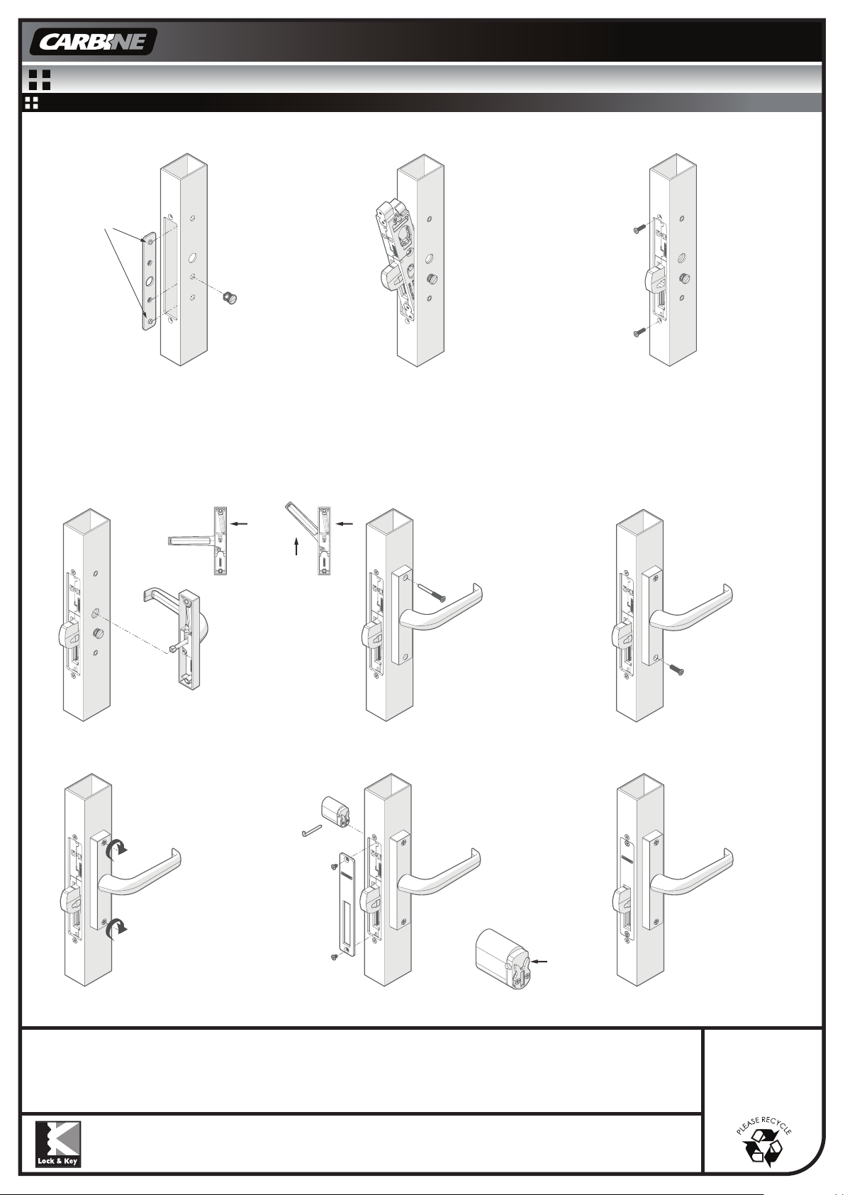
5I Installation is now complete.
5H Insert oval key cylinder
and retainer pin if required.*
Attach cover plate to lock and
secure with 2x M4x6mm CSK
Screws (supplied with lock).
Insert oval key
cylinder and
retainer pin
if required.
*With rabbit ear / R cam fitted on
the oval cylinder.
5E Insert top mounting
screw pin through the
top mounting plate hole
on the faceplate and into
lock. Fasten to retain, do
not tighten.
5F Insert bottom mounting
screw through the bottom
mounting plate hole on the
faceplate and into lock.
Fasten to retain, do not
tighten.
5D Ensure handle is in the
up position, spring at the
top and the lock bolt is
extended.
Position the faceplate to the
door and insert the spindle
into the lock drive.
CFB-EH FLIP BOLT MORTICE LOCK - EGRESS HANDLE
5G Align furniture to be even
and parallel with door edge.
Securely tighten both mounting
screws.
Test handle operation.
This way up
Upright Position
5A Insert mounting plate with bosses
facing handle side into door cavity*,
do not drop inside door.
Firmly press mounting plate clip through
the door extrusion into the mounting plate.
5C Secure with 2x M4x16mm CSK
Screws (supplied with lock).
*with the boss
through drilled holes
5B Insert CFB-D / CFB-HB
lock into door cavity.
ENSURE BOLT IS EXTENDED.
5. INSTALLATION OF MAIN LOCK AND EGRESS HANDLE

Other Carbine Lock manuals

Carbine Armadillo HASPLOCK User manual

Carbine

Carbine Armadillo HASPLOCK User manual

Carbine CDL7100-KDSC User manual

Carbine

Carbine CDL7100-KDSC User manual

Carbine CFB-HB User manual

Carbine

Carbine CFB-HB User manual

Popular Lock manuals by other brands

Phoenix KS0002C Series operating instructions

Phoenix

Phoenix KS0002C Series operating instructions

D+H LAH 65-K-BSY+ manual

D+H

D+H LAH 65-K-BSY+ manual

Simons Voss Technologies PinCode keypad quick guide

Simons Voss Technologies

Simons Voss Technologies PinCode keypad quick guide

SCS Sentinel XO 404 Installation and operation manual

SCS Sentinel

SCS Sentinel XO 404 Installation and operation manual

hune 6000RL-M user manual

hune

hune 6000RL-M user manual

Edsbyn 59 manual

Edsbyn

Edsbyn 59 manual

SISO 14.60.290-0 user manual

SISO

SISO 14.60.290-0 user manual

UCS BRAVO user manual

UCS

UCS BRAVO user manual

Safety 1st 3202001400 Installation

Safety 1st

Safety 1st 3202001400 Installation

COMPX Stock Locks C1802 Dimensional drawing

COMPX

COMPX Stock Locks C1802 Dimensional drawing

Kaadas K20 Pro Max user manual

Kaadas

Kaadas K20 Pro Max user manual

Clavis SECU S1000 Mounting instructions

Clavis

Clavis SECU S1000 Mounting instructions

Corbin Russwin ASSA ABLOY Museo MP6600 Series installation instructions

Corbin Russwin

Corbin Russwin ASSA ABLOY Museo MP6600 Series installation instructions

Griffon M-LOCKS user manual

Griffon

Griffon M-LOCKS user manual

Visionis VS-SS600-G user guide

Visionis

Visionis VS-SS600-G user guide

Adel AD-E7F4 Operation manual

Adel

Adel AD-E7F4 Operation manual

Glue GL04 Series user guide

Glue

Glue GL04 Series user guide

Promet PS600/E31 user manual

Promet

Promet PS600/E31 user manual

manuals.online logo
manuals.online logoBrands
  • About & Mission
  • Contact us
  • Privacy Policy
  • Terms and Conditions

Copyright 2025 Manuals.Online. All Rights Reserved.