CARBIS TCG-2000 User manual

REVISED 12/17/2018 TCG-2000-OSP-M © SAM CARBIS SOLUTIONS GROUP, LLC, 2018, WITH ALL RIGHTS RESERVED PAGE 1
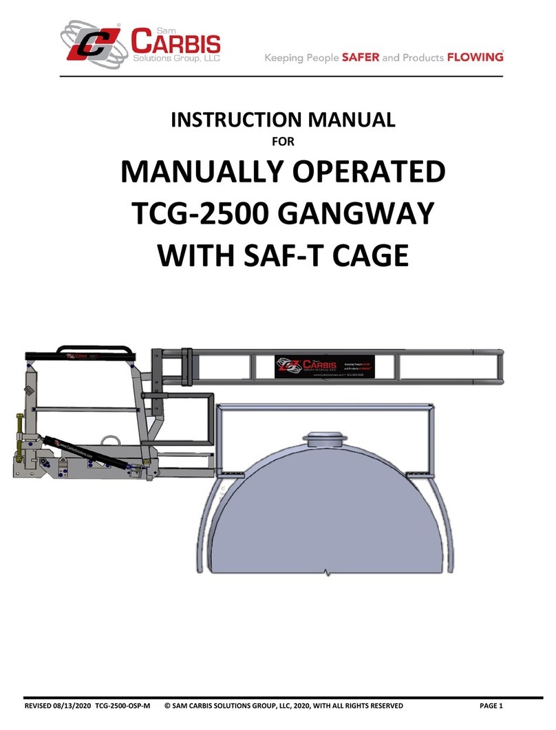
INSTRUCTION MANUAL
FOR
MANUALLY OPERATED
TCG-2000 GANGWAY
WITH SAF-T CAGE

REVISED 12/17/2018 TCG-2000-OSP-M © SAM CARBIS SOLUTIONS GROUP, LLC, 2018, WITH ALL RIGHTS RESERVED PAGE 2
TABLE OF CONTENTS
Section 1) ….…………………………………………….…………………………………………………………………. INTRODUCTION
Section 2).…………………...……………………………………………………………………………….....PRODUCT DESCRIPTION
Section 3) ………………………………………………………………………………………………………………..SAFETY LANGUAGE
Section 4) …………………………….……………………………………………………………………………………………. OPERATION
Section 5) ………………………………….……….……………………………………………………….…………TROUBLESHOOTING
Section 6) ……………………………….…………. ….……………………………………………………………………. MAINTENANCE
Section 7) ……………………………….….……...………………………………………………………. INSTALLATION AND SETUP
Section 8) …. ….……………….….…...….…. ….…………………….……………SPECIFICATION SHEETS AND DRAWINGS

REVISED 12/17/2018 TCG-2000-OSP-M © SAM CARBIS SOLUTIONS GROUP, LLC, 2018, WITH ALL RIGHTS RESERVED PAGE 3
1) INTRODUCTION
a) PLEASE READ THIS FIRST PRIOR TO INSTALLATION OR OPERATION
i) On behalf of Sam Carbis Solutions Group LLC., thank you for your purchase of our safety equipment. It is
our pleasure helping you with all your fall protection and product handling needs. We value our customer
relationships and to ensure you get the most out of your equipment, our experienced support team is
available for you to contact throughout your equipment service life. While this manual fully covers our
product, if you should you have any questions or concerns please contact at 1-800-948-7750 or 1-843-669-
6668 for international customers.
ii) Please carefully read this Installation, Operation, and Mainten an ce Man ual as it is an in tegral
pa r t of y o u r p u rc ha s ed Carbis equipment. It is the Owner’s responsibility ensuring all personnel who
operate and or maintain the Carbis equipment first receive comprehensive training. It is also the Owner’s
responsibility ensuring appropriately documented maintenance and inspection activities are, including any
abnormal operating condition and its associated root cause evaluation, followed by corrective actions
implemented to eliminate recurrence. Any identified abnormal operating conditions should be cause for
discontinuing use until contacting Sam Carbis Solutions LLC for further assistance.
iii) With aging of equipment and associated service life-limiting variables, such as corrosion, fatigue, wear,
etc., remedy these discrepancies as soon as possible during periodic maintenance to preclude operational
failure
iv) This manual provides guidance to operating and maintenance personnel in the matter of safe
operation and recommended practices, it is not, and cannot be, a substitute for well-trained personnel
and for successful and trouble-free operation. Great reliance must be placed upon the knowledge,
background, and experience of the operating and or maintenance personnel with this manual serving as a
guide. The warranty on the equipment is automatically voided if the information contained in this manual
is disregarded whether willfully or inadvertently.
v) This product was inspected prior to shipment and meets Carbis’ Quality Control Standards. It is important
to completely review the information contained in this manual before operating the unit in addition to:
1) Upon delivery, inspect the equipment for shipping damage or any loose or missing hardware. All
factory installed fastening hardware has been tightened prior to shipment. If loosening any fastening
hardware, whether factory or field installed, it must be re-tightened before use.
vi) It is imperative operating and maintenance personnel prior to using the equipment become familiar
with the safety information contained in section 3) SAFETY LANGUAGE.
vii) Visually inspect all safety placards, signs, and decals for serviceability, visibility and legibility. Operating
personnel must be familiar with the contents of such placards, signs, and decals. See Section 3) b) for
SAFETY LABEL DESCRIPTIONS for the description of all safety signs that appear on the equipment
described in this manual.

REVISED 12/17/2018 TCG-2000-OSP-M © SAM CARBIS SOLUTIONS GROUP, LLC, 2018, WITH ALL RIGHTS RESERVED PAGE 4
viii) U.S. Patents 6,814,522; 8,479,884; 8,813,912, 9,567,759; 8,745,799; 9,546,458; 8,656,556; and other
patents pending protect the equipment shown in this manual.
b) VEHICLE POSITIONING
i) Carbis designs gangways in a variety of styles, sizes, and materials accommodating specific customer-
requirements in applications including varying heights and types of vehicles. Subsequently, with each
gangway, Carbis provides customer-approved Engineering Drawings and or scope data documenting key
dimensional relationships between a particular-type vehicle and the accessing gangway including safety
cages as applicable. P rior to operational use refer to the specific customer-approved Carbis equipment
Final Drawings for familiarization with vehicle dimensional relationships in determining required for
proper vehicle positioning.
ii) Incorrect gangway positioning on top of the vehicle can cause a dangerous condition
leading to a potential for damage, serious injury or death. The access equipment when extended
protrudes into the standard vehicle clearance envelope. Always leave the gangway in the full up and
stored position until the intended underneath positioned vehicle comes to a complete stop and given
proper permission to access. Always leave the gangway stored when not in use to prevent damage from
traversing vehicles. Keep hands away from moving areas (See FIGURE 1-1 and FIGURE 1-2).
FIGURE 1-1 GANGWAY STORED AND FIGURE 1-2 GANGWAY IN WORKING POSITION

REVISED 12/17/2018 TCG-2000-OSP-M © SAM CARBIS SOLUTIONS GROUP, LLC, 2018, WITH ALL RIGHTS RESERVED PAGE 5
iii) RAIL CAR POSITIONING
With a railcar centerline considered as a fixed constant relationship with Carbis equipment, correct
railcar positioning is along the length of the track r e q u i r e s c o r r e c t operator input. Carbis’ standard
gangways r e q u i r e the rail car spotted with the r a i l c a r access area centered on the gangway. With
Carbis’ pivoting or tracking gangways, the rail car access area requires spotting within the gangway
pivoting range of 10 degrees each side of center.
iv) TRUCK POSITIONING
Given the portable nature of a truck, the truck driver’s abilities largely determine correct spotting.
Therefore, consider using visual spotting aids such as bollards, curbs, painted guidelines, suspended
markers (i.e., tennis balls), etc. enhancing the driver’s positioning ability. See FIGURE 1-3 below for proper
vehicle positioning with Carbis’gangways. Tracking gangways allow gangway positioning along the length
of the truck.
v) DEVIATIONS
Unexpected vehicle configuration deviations can cause a hazard even when proper positioning has taken
place. Training for hazard recognition by all operators is required for fall protection equipment (Ref: OSHA
1910.30).

REVISED 12/17/2018 TCG-2000-OSP-M © SAM CARBIS SOLUTIONS GROUP, LLC, 2018, WITH ALL RIGHTS RESERVED PAGE 6
Vehicle positioned too close to the
TCG-2000. This blocks access to the
hatch creating incorrect cage
spacing and a fall hazard
Vehicle correctly positioned to the
TCG-2000. This allows safe access
to the hatch with correct cage
spacing thus mitigating a fall. (See
final drawing for proper location).
Vehicle positioned too far from
the TCG-2000. This blocks
access to the hatch creating
incorrect cage spacing and a
fall hazard
FIGURE 1-3

REVISED 12/17/2018 TCG-2000-OSP-M © SAM CARBIS SOLUTIONS GROUP, LLC, 2018, WITH ALL RIGHTS RESERVED PAGE 7
2) PRODUCT DESCRIPTION:
MANUALLY OPERATED TCG-2000 GANGWAY WITH SAF-T CAGE
SEE PROJECT-SPECIFIC DRAWINGS, FIGURES WITHIN THIS SECTION,
AND SECTION 8) SPECIFICATION SHEETS AND DRAWINGS
Only the person performing the work can operate Carbis equipment. No other personnel
are authorized to operate at any time. Failure to adhere to this caution may cause a person to fall risking
injury or damage to equipment. All other personnel should maintain a 10-foot/3-meter clearance while
Carbis Equipment is in motion.
Do not operate Carbis Equipment for any other purpose other than its intended design. Do
not modify Carbis equipment to perform beyond its factory settings. Failure to do so could cause a
malfunction possibly damaging equipment and causing injury. Contact Carbis for service
a) MECHANICAL EQUIPMENT (See FIGURE 2-1.)
i) GANGWAY
The TCG-2000 Series Gangway is a manually operated, spring-assisted, articulating gangway providing safe
access to various types of vehicles of different heights for operators to safely perform the work required on
the vehicles within the fall protection enclosure provided by the safety cage.
1) A galvanized steel base tread that is either fixed mounted directly to a platform, horizontally pivot
mounted, or track mounted.
a) The TCG-2000 Operated Gangway requires assembly, connections, and startup before use. See
section 7) INSTALLATION AND SET UP for instructions.
b) The load capacity for Carbis series TCG-2000 gangways including user, PPE, and any equipment is
500 lbs./227 Kg.
2) The gangway consists of stringers articulating about the base tread with top handrails and midrails
pivoting about the base tread uprights. The outboard uprights support the outer end of the top
handrails and midrails, supporting safety cages or seatainer treads. Walk surface options are open
serrated metal plank, fiberglass, or serrated bar grating, and are so noted on the Final Drawings
Gangway material options are designated by the letter in the model number noted on the Final
Drawings:
a) A –Aluminum
b) S –Mill Steel
c) P –Primed Steel
d) G –Galvanized Steel
3) Stringer bottom leading edge mounted bumpers give added protection against vehicle damage.
4) An optional base tread foot lock mounted on the base tread holds the gangway in the upright stored
position. The use of slotted chain locks secures the gangway in the stored position above horizontal.

REVISED 12/17/2018 TCG-2000-OSP-M © SAM CARBIS SOLUTIONS GROUP, LLC, 2018, WITH ALL RIGHTS RESERVED PAGE 8
NOTE: For gangways without foot locks, the chains are required to hold the gangway in the stored
position. The upright stored position is typically 85 degrees above horizontal.
5) Stringer attached adjustable chains supported by base tread upright mounted slotted tube chain locks
when secured hold the gangway in any desired position within the normal working range of 15
degrees above to 15 degrees below horizontal. (See FIGURE 2-1).The range may be modified within
the limits to accommodate options.
6) The slotted tube design secures the chain throughout the full range of gangway movement from the
lowest working position up to the fully raised stored position.
7) The chains provide strength and equipment stability allowing access to a variety of trailers or railcars.
NOTE: The chains when correctly slotted into the chain locks secure the gangway when not in use.
8) Covered springs mounted between the uprights and the stringers provide tension adjustment to
minimize the push/pull force required to articulate the gangway.
9) An attached pull-up rope aids the operator to return the gangway to the upright stored position.
10) G angway mounted cages employ additional grab rails mounted perpendicular to the outboard
uprights o n each side of the gangway compensating for a n inboard handrail gap created when
lowering the gangway.
11) When in the stored position, the gangway ‘s attached serial number on the first tread left-hand side is
visible. Note: Always reference this serial number when contacting Sam Carbis Solutions Group with
any questions or concerns.
12) Gangways have an optional pivoting outboard upright and cage leveling mechanism (see FIGURE 2-2).
Mounted on the upper half of each left and right pivoting outboard upright, the cage leveling
mechanism consists of back-to-back channels: one on the gangway fixed upright and one on the
pivoting upright. Mounted between the channels is a thru threaded rod with a series of back-to-back
adjustment nuts and washers on both sides of each channel.
FIGURE 2-1 TCG-2000 GANGWAY GENERAL ARRANGEMENT

REVISED 12/17/2018 TCG-2000-OSP-M © SAM CARBIS SOLUTIONS GROUP, LLC, 2018, WITH ALL RIGHTS RESERVED PAGE 9
ii) GANGWAY FOOT LOCK
Most Carbis manual sprung gangways employ a single manually functioning foot lock. A single base tread
mounted foot lever when depressed activates the foot lock unlocking function. When lowering the
gangway, depressing the foot lever while pushing forward on the handrails extends the foot lock spring and
releasing the mechanical foot lock for the gangway to extend. The gangway locking function engages when
fully raised to the stored position.
b) MODIFIED GANGWAY
i) For any modified gangway including the addition of ancillary components not otherwise identified
above, see project-specific drawings that reflect the modification or addition.
ii) SAF-T CAGE
1) The SAF-T Cage is either a monolithic or two-piece cage structure that bolts directly to the outboard
upright of the gangway. The cage can bolt in either the high or low position as determined by site-
specific needs to maintain the required fall protection criteria (see FIGURE 2-2).
FIGURE 2-2 TCG-2000 GANGWAY WITH OPTIONAL CAGE LEVELING SYSTEM
iii)LIFT RESTRICTING DEVICE (See FIGURE 2-3)
(NOTE: Not all TCG-2000 gangways include the Lift Restricting Device)
The Lift Restricting Device (LRD™) design impedes the gangway from inadvertent or premature raising
while operating personnel occupy the top of the vehicle. The Lever Arm Release Handle design releases
the LRD™ while simultaneously raising the gangway to the stored position as an operator exits the
gangway. A protective cover prevents personnel from overriding the LRD™ while on the vehicle. The

REVISED 12/17/2018 TCG-2000-OSP-M © SAM CARBIS SOLUTIONS GROUP, LLC, 2018, WITH ALL RIGHTS RESERVED PAGE 10
LRD™ mounts between the inner end of the top rail and the upper half of the outboard upright and
consists of the following:
1) A linear rail with ratcheting angled teeth mounted on the underside; the rail is pinned on one end to a
lug supported on the top rail of the gangway by double U-bolts. The opposite end of the rail slides
into an extension tube pinned to a support bolted to the outboard handrail of the gangway.
2) Pinned to a lug mounted on the underside of the linear tube is a ratcheting pawl with a pivoting catch
engaging a tooth of the linear rail and holding the gangway in place, impeding gangway lift.
3) The LRD™ Lever Arm Release Handle design actuates by a pull-up rope supplied with the LRD. The
Release Handle mounts on the LRD™ ratcheting pawl. Pulling the pull-up rope pulls the handle
towards the platform causes the ratcheting pawl to pivot, releasing the catch from its engagement
with the rail gear tooth and raises the gangway to the stored position with the LRD™ pull-up rope.
FIGURE 2-3 (4 Step LRD™)
c) OPTIONAL TCG TRACK AND CARRIAGE WITH TCG-S910.1 TRACK LOCK MECHANISM (SEE FIGURE 2-4 and
FIGURE 2-5).
i) The galvanized steel track and carriage system includes the following features:
1) A track assembly integrated to a platform structure or as a separate assembly bolting to the face of a
fixed platform structure.
2) A carriage mounted gangway base tread that rolls on the track assembly.
3) A track top section capturing the top rollers with the bottom section supporting the carriage rollers.
4) A removable stop inserted through the top surface end holes preventing the carriage from rolling
past the track ends.
5) The main carriage assembly consists of a plate weldment with top and bottom rollers mounted at
each end. The top rollers ride on the vertical inside track leg and the bottom rollers ride along the
bottom outside face of the carriage mounting plate and are bolted to the backside of the
gangway.
6) Carriage rolling assemblies consist of shaft-supported rollers mounted on base tread mounting
plate.

REVISED 12/17/2018 TCG-2000-OSP-M © SAM CARBIS SOLUTIONS GROUP, LLC, 2018, WITH ALL RIGHTS RESERVED PAGE 11
FIGURE 2-4 FIGURE 2-5
d) OPTIONAL TCG-S910.1 TRACK LOCK MECHANISM (SEE FIGURE 2-6).
All TCG gangways with the track and carriage option also include the TCG-S910.1 Track Lock Mechanism, a
safety device preventing gangway damage from inadvertent rolling along the track when not in the stored
position. The mechanism consists of a combination of automatic and manual lock functions as described
below.
i) The automatic function of the mechanism consists of the following features:
1) A housing assembly with a curved release lever arm on one end and a brake pad pivot arm on the
opposite end. Both arms are positioned between and bolted to each arm’s upper pivot point
housing side plates. A pair of flat bar spacers bolted below the housing between both arms allow the
arms to pivot together. As the springs extend or retract an extension spring pinned between each
arm’s bottom extension changes each arm’s top end geometry.
2) The assembly bolts through the gangway base tread side plate holes. The top of the curved release
lever arm includes a bent leg engaging the gangway stringer top edge as the gangway raises to the
stored position.
3) As the gangway raises to the stored position, the stringer engages the bent leg of the release lever
arm causing the spring to extend. As the spring extends, the brake pad pivot arm pivots disengaging
the brake pad from the track. Once the gangway is in the stored position, the brake pad releases
from the track allowing the gangway to manually track.
4) Whenever the gangway is not in a stored position, the release lever arm disengages from the stringer
thereby causing the spring to press against the track brake pad preventing the gangway from
tracking.
5) The track lock mechanism automatic lock function remains inactive whenever the gangway is
stored permitting gangway free roll movement along the length of the track. As an added safety
feature, the track lock mechanism manual track lock lever only engages the gangway is in the stored
position. When engaged, the manual track lock lever actuates a second brake pad against the track
preventing the gangway from inadvertently rolling along the track by any external force such as wind.

REVISED 12/17/2018 TCG-2000-OSP-M © SAM CARBIS SOLUTIONS GROUP, LLC, 2018, WITH ALL RIGHTS RESERVED PAGE 12
FIGURE 2-6
e) OPTIONAL TCG PIVOT MOUNT (SEE FIGURE 2-7 AND FIGURE 2-8).
i) The pivot mount system consists of a gangway base tread with a male pivot post mounted on the
underside and a tread extension mounted on the platform side of the tread that includes the following
features:
1) The male pivot post engages a female pivot-mounting sleeve and rests on a wear pad.
2) The range of pivot rotation is 10 degrees each side of center.
3) Brackets either bolted or welded to a platform and surface mounted or underslung below
the platform structure support the female pivot-mounting sleeve.
4) The pivot-mounting system can be retrofitted to an existing pivot support bracket.
FIGURE 2-7 FIGURE 2-8

REVISED 12/17/2018 TCG-2000-OSP-M © SAM CARBIS SOLUTIONS GROUP, LLC, 2018, WITH ALL RIGHTS RESERVED PAGE 13
3) SAFETY LANGUAGE
a) HAZARDS
The following safety notes are grouped by hazard and used throughout this manual. Please carefully read and
understand these notes before performing any task contained in this manual.
i) Failure to comply with these DANGER warnings WILL result in serious injury or death.
1) This equipment CAN conduct electricity.
2) Perform required grounding procedures per the owner’s safety code.
3) Do NOT allow this unit to contact live electrical wires.
ii) Failure to comply with these warnings COULD result in serious injury or death.
1) Correct vehicle positioning is imperative to ensure proper deployment and function of Carbis
equipment. Incorrect vehicle positioning or improper use of this equipment increases the risk
of serious injury or death. Carbis equipment is designed to function only as described in this
manual and depicted on applicable drawings. IT IS THE SOLE RESPONSIBILITY OF THE OWNER
TO ENSURE PROPER USE OF CARBIS EQUIPMENT. IF ANY QUESTIONS, PLEASE CONTACT
CARBIS BEFORE PROCEEDING.
2) Before accessing Carbis equipment, correctly spot a vehicle per Figure 1-1 then ensure Carbis
equipment is properly deployed, supported, and secured.
3) Operator must ensure nonessential personnel are clear of Carbis equipment during any
controlled operation.
4) No personnel including the operator must not occupy Carbis equipment while it is in motion.
5) Do not force Carbis equipment by any means to overcome any seen or unseen obstacle or
obstruction. You must use Carbis Equipment within its designated operating limits.
6) Keep hands clear of chains while gangway is in motion.
7) If the equipment will not function as intended, discontinue use and immediately contact
maintenance.
8) Never make repairs of damaged or missing parts. Replace missing parts only with Carbis
approved suitable parts.
9) Material loaded onto or unloaded from vehicles may present a health hazard. It is the sole
responsibility of the owner ensure operating personnel are familiar with any associated
material hazards and implement appropriate safety measures to protect personnel against such
hazards.
10) If installed, do not tamper with, disable, remove, or override lift restricting device (LRD™).
iii) Failure to comply with these cautions COULD result in personnel injury or damage to
equipment
1) Carefully read this manual before unpacking and installing Carbis equipment.
2) Only permit personnel in good physical condition and trained in the proper operation of this
equipment to operate it.
3) When operating Carbis Equipment personnel should always wear appropriate Personal

REVISED 12/17/2018 TCG-2000-OSP-M © SAM CARBIS SOLUTIONS GROUP, LLC, 2018, WITH ALL RIGHTS RESERVED PAGE 14
Protective Equipment (PPE), such as gloves, safety glasses, safety shoes, helmet etc.
4) For chain-supported Carbis gangways, both locking chains must be correctly engaged in the
chain lock slots supporting the gangway before accessing. Slack or unequal chain adjustment
may result in unanticipated movement and loss of balance when walking or standing on the
equipment.
5) For operator safety, Carbis recommends the equipment be stored and not used when wind
speed gusts exceed 35 mph/56 kph.
6) Unit is not to rest on the vehicle at any time.
iv) Failure to comply or adhere to these notices COULD result in equipment damage or
degradation.
1) Qualified maintenance personnel must be familiar with manual instructions as well as all
accompanied system schematics and drawings before performing component adjustments.
2) Ensure local safety LOCKOUT-TAGOUT procedures are correctly adhered before performing
work on Carbis Equipment.
NOTICE

REVISED 12/17/2018 TCG-2000-OSP-M © SAM CARBIS SOLUTIONS GROUP, LLC, 2018, WITH ALL RIGHTS RESERVED PAGE 15
b) SAFETY LABEL DESCRIPTIONS
Please ensure the following safety labels below are eligible and properly affixed on the equipment as described
in this manual before use. Contact Carbis when requiring replacement labels
AL-157 AL-159.1 AL-156
(Inside right of base tread) (Inside left of base tread) (Right top handrail)

REVISED 12/17/2018 TCG-2000-OSP-M © SAM CARBIS SOLUTIONS GROUP, LLC, 2018, WITH ALL RIGHTS RESERVED PAGE 16
AL-305-R1 (Inside left and right handrails)
AL-160 (Left top handrail)
AL-162 Used with LRD™if installed (Inside right top handrail)
GWLIFT1.5X3.75 Used for TCG installation (positioned on outside Left
and Right of outboard Uprights See Figures 7-1 and 7-2)
AL-163(Affixed to the LRD™if installed)

REVISED 12/17/2018 TCG-2000-OSP-M © SAM CARBIS SOLUTIONS GROUP, LLC, 2018, WITH ALL RIGHTS RESERVED PAGE 17
i) SAFETY LABELS LOCATION (See Figure 3-1) for safety label locations on this equipment as described in
this manual. For TCGs with adjustable uprights, see Figure 7-2 for lift label placement.
FIGURE 3-1
SAFETY label LOCATIONS
NOTE: Image shown is TCG-2000 with fixed uprights
FIGURE 3-2
TCG-2000-OSP WITH SAF-T CAGE (OPERATOR LOCATED OPERATIONAL SIGN)

REVISED 12/17/2018 TCG-2000-OSP-M © SAM CARBIS SOLUTIONS GROUP, LLC, 2018, WITH ALL RIGHTS RESERVED PAGE 18
FIGURE 3-2
TCG-2000-OSP FOR OPTIONAL CEMENT INDUSTRY HTQIKCAGE (OPERATOR LOCATED OPERATIONAL SIGN)
4) OPERATION
a) PRE-USE INSPECTION
i) For systems including loading arms, see separate instruction manual for operation.
II) DO NOT USE Carbis Equipment if wind speed gusts exceed 35 mph.
1) Gangway weight limit design is for single person occupancy with PPE, tools and must not exceed
500 lbs./227Kg.
2) Visually inspect the assemblies before use. If discovered damaged or broken components
replace before returning to service. If component replacement requires any disassembly, refer
to Section 7) INSTALLATION AND SETUP for restoring the system to operational status.
3) Verify all safety placards, signs, and labels are clearly visible, legible, and in good repair.
Operating personnel must be familiar with the contents of such placards, signs, and labels. See
section 3 SAFETY LANGUAGE b) SAFETY LABEL DESCRIPTIONS for all safety labels appearing on
the equipment described in this manual.
4) Before operating the equipment, inspect between the e quipment and the ve hicle for
any obstruction impeding correct movement or creating a tripping hazard. Remove any
obstructions before proceeding.

REVISED 12/17/2018 TCG-2000-OSP-M © SAM CARBIS SOLUTIONS GROUP, LLC, 2018, WITH ALL RIGHTS RESERVED PAGE 19
5) Keep hands clear of the gangway chains while the gangway is in motion. If the
gangway is already positioned down over a vehicle, first ensure no personnel have accessed the
gangway or vehicle before storing the gangway and cage in the (fully up) stored position with
the safety chains correctly secured. Damage to equipment or injury to personnel may occur.
iii) Before spotting any vehicle, the gangway must always be in the stored (fully
up) position before proceeding. Do not extend the gangway and extended cage out into the
standard vehicle clearance envelope until the vehicle comes to a full rest stop and proper
permission given to access the vehicle. When not in use, the gangway and extended cage must
always be in the full up stored position to prevent inadvertent damage from traversing vehicles.
Kee
p
hands
clear of moving areas while gangway
is
in motion.
iv) With no vehicle berthed, verify the gangway is in the stored position. Correctly spot the accessed vehicle
per Figure 1-1 noting the work area in front of the gangway. If available, use visual aids to assist in
spotting the vehicle Continue to b) if track mount and pivoting installed. Otherwise, proceed to c).
b) TRACK MOUNT AND PIVOTING OPERATIONS (IF INSTALLED)
i) For pivot-mounted gangways, pivot the gangway to the desired position.
ii) If discovering a broken or missing TCG-S910.1 Track lock Mechanism
Spring, do not operate the gangway. If not correctly functioning, do not attempt to repair.
Contact Maintenance or Carbis immediately for assistance or replacement parts.
iii) For track-mounted gangways, perform the following sub-steps:
1) With the gangway body locked in the upright stored position, release t he manual track lock
Lever and manually roll the gangway to the desired working position.
2) With the gangway properly positioned along the track, open the swing gate and deploy the
gangway for operation. Once the gangway releases from the stored position, the brake lock pad
will automatically engage the roller track preventing the gangway from tracking.
iv) Do not attempt to roll the deployed gangway along the track. Doing so can damage
the equipment.
c) MANUAL OPERATING SEQUENCE
i) If the gangway will not raise or lower, or if the foot lock will not engage when
pushed or pulled to the d e s i r e d position, immediately discontinue use and contact Maintenance.
Failure to follow instructions or attempt to dislodge obstructions may result in severe injury or death.
1) Ensure vehicle correctly spotted per (Figure 1-1) above.
2) If vehicle is not properly centered, a gap may be created which can lead to death
NOTICE

REVISED 12/17/2018 TCG-2000-OSP-M © SAM CARBIS SOLUTIONS GROUP, LLC, 2018, WITH ALL RIGHTS RESERVED PAGE 20
or serious injury.
3) Set each chain with the next to the last link engaged in the chain lock slot.
4) While depressing the foot lock, place both hands on the top handrail and push outward.
5) After completely lowering the gangway over the vehicle, equally adjust the chains allowing for
stable gangway support before securing the chain links in the chain lock slots.
6) Other than limit switches (if installed), The gangway is not to rest on the vehicle. If,
so raise the gangway and reposition the vehicle accordingly then reaccomplishing steps 1-5.
7) Once completing the required work and before exiting the top of the vehicle, ensure the area is
clear of all equipment and tools.
8) Ensure no one has inadvertently raised the gangway before using the gangway to exit.
9) Do not attempt to raise gangway and cage while personnel or tools are on the
vehicle, gangway or cage; do not attempt to dislodge obstructions. Any attempt could result in
severe injury or death.
10) Ensure no one has inadvertently raised the gangway before using the gangway to exit.
11) After all personnel exited off the vehicle and gangway and on to the platform, turn around facing
the gangway and firmly grab the pull-up rope attached to the LRD™ handle (if installed). Firmly pull
the rope to disengage the LRD™ and raise the gangway to the stored position.
12) It is not necessary to depress the foot lock pedal when raising the gangway; however, ensure the
foot lock has engaged the bolt of the foot lock mechanism.
13) Pull the chains taut to additionally secure the gangway in the stored position. For gangways not
equipped with a foot lock (special order), use the chains to secure the gangway in the stored
position.
ii) For track-mounted TCG’s, when finished with the operation perform the following:
1) With the gangway locked in the upright stored position, push down the manual track lock lever
engaging the brake and preventing the gangway from free rolling along the track.
5) TROUBLESHOOTING
a) GENERAL
i) Failure to comply with these warnings CAN result in serious injury, death, or damage to
equipment. It is the Owner’s responsibility to ensure procedures in this manual are correctly followed.
1) Ensure maintenance personnel troubleshooting Carbis equipment are completely familiar with the
equipment, have thoroughly read this manual, and possess the necessary maintenance skillset to
work on this equipment. Contact Carbis if requiring further troubleshooting assistance.
2) Discontinue equipment use until maintenance issues are correctly resolved.
Table of contents
Other CARBIS Lifting System manuals
Popular Lifting System manuals by other brands

Screen Technics
Screen Technics INTERFIT Vertical Up Lift instructions

Custom Equipment
Custom Equipment Hy-Brid Lifts 2 Series Maintenance and troubleshooting manual

Savaria
Savaria omega owner's manual

RITE-HITE
RITE-HITE Genisys HL-900 owner's manual

Skyjack
Skyjack ZB2044 operating manual

Granberg
Granberg Kitchen Appliance Lift instruction manual

Aquatec
Aquatec orca operating instructions

CRAIN
CRAIN 280 instruction manual

Aqua Creek Products
Aqua Creek Products Ranger F-411RPL-AT1-EU manual

Atlas Equipment
Atlas Equipment 414A user manual

Dolphin
Dolphin Poollift Neptune with Transporter Operating and Product Care Instructions

Stratus
Stratus SAE-F14X Installation, operation & maintenance instructions