Carbolite Gero Eurotherm 2216 User manual

MC11 –1.05
Operating Instructions
Temperature Controller
Eurotherm 2216
Including 2132 or 2116 Overtemperature Controller Instructions
See also the main manual for the oven or other product to
which the controller is fitted.
CONTENTS
section page
1 2216 –Description 2
2 2216 –Basic Operating Instructions 3
3 Altering the Power Limit 5
4 2132 & 2116 –Description 6
5 2132 & 2116 –Operation 6

2216 Controller
2 MC11 –1.05
12216 –DESCRIPTION
1.1 2216 Controller
The model 2216 controller is made by Eurotherm, and is fitted by Carbolite Gero configured for
immediate use. It is a digital instrument with PID control algorithms. It is supplied as a sleeve
fitted controller.
The 2216 is supplied configured for easy use as a simple temperature controller, where on setting
the required temperature the controller immediately attempts to reach and maintain it.
A ramp-to-setpoint feature is available which may be used to limit the heating rate. This is shown
diagrammatically in figs 1 & 2.
The controller does not contain a real-time calendar, and is not subject to century-end date
problems.

2216 Controller
MC11 –1.05 3
22216 –BASIC OPERATING INSTRUCTIONS
2.1 Furnace or Oven Controls
Most Carbolite Gero products are fitted with an “Instrument Switch” which cuts off power to the
controller and other parts of the control circuit. See the instruction manual for the furnace or oven
for the overall operating instructions.
To operate the 2216 there must be power to the furnace or oven, and the Instrument switch must
be on. If a time switch is included in the furnace or oven circuit, this must be in an On period.
2.2 The 2216 –Operation
When switched on, the controller lights up, goes through a short test routine, and then displays
the measured temperature and starts to control. The output light glows or flashes as heating
occurs.
The Page key allows access to parameter lists within the controller; most lists and parameters
are hidden and cannot be accessed by the operator because they contain factory-set parameters
which should not be changed.
A single press of the page key displays the temperature units, normally set to °C; further
presses reveal the lists indicated in the Navigation Diagram in section 2.6. The Scroll key
allows access to the parameters within a list. Some parameters are display-only; others may be
altered by the operator. Some parameters only appear in appropriate circumstances –for
example, working setpoint does not appear if setpoint ramp rate is Off.
A single press of the scroll key displays the temperature units; further presses reveal the
parameters in the current list indicated in the Navigation Diagram.
To return to the Home list at any time, press Page and Scroll together, or wait for 45
seconds.
The Down and Up keys are used to alter the setpoint or other parameter values.
2.3 Basic Operation
Normally no operator action is required other than entering the setpoint, as the 2216 starts to
control on being switched on, as described above.

2216 Controller
4 MC11 –1.05
2.4 Altering the Setpoint
With the display at “home”, showing the measured temperature, press Down or Up once to
display the setpoint; press again or hold down to adjust it. The display returns to the measured
temperature when no key is pressed for 0.5 seconds.
2.5 Altering the Ramp Rate
It is possible to limit the rate of heating by setting a ramp rate. Press Scroll until the legend
SPrr (SetPoint ramp rate) is displayed. Use Down or Up to display and adjust the value.
The ramp rate sets the maximum rate of heating or cooling in degrees per minute. A value of OFF
cancels the ramp rate, allowing heating and cooling at the maximum rate. When this feature is in
use, there is a “working setpoint” which can be viewed at any time by scrolling to w.SP and
pressing or .
Fig 1 and fig 2 indicate the possible difference between running without and with a ramp-to-
setpoint value (depending on the load and the value used).
2.6 2216 Navigation Diagram
OP.Hi
SPrr
Home
List
Output
List
Access
List
1000
1000
oP
ACCS
OP
codE
*C
*C
setpoint ramp rate
OFF or value
power limit
setting, if
present
output power,
read only
measured temperature
and setpoint; use
/
to alter setpoint
for factory access to
lists and parameters
not available to the
operator

2216 Controller
MC11 –1.05 5
3ALTERING THE POWER LIMIT
3.1 Overview
Depending on the furnace or oven model the power limit parameter OP.Hi (Output High) may be
accessible or hidden.
For silicon carbide heated furnaces the parameter is accessible to allow for compensation for
element ageing (see the appropriate section in the furnace manual). In wire-heated chamber or
tube furnaces, reducing the power limit is a convenient method of improving control at low
temperatures, as outlined below.
The power limit may be set to zero to permit demonstration of the controls without heating.
In many models the power limit setting depends on the supply voltage; usually the furnace or
oven manual contains details: if in doubt, contact Carbolite Gero for advice.
The power limit parameter does not apply to the overtemperature controller, if present.
3.2 Altering the value
Press Page until oP (output list) is displayed. Press Scroll until OP.Hi (Output High) is
displayed. Press Down or Up once to display the value of OP.Hi and write down the value.
To alter the value, use Down or Up . Note that setting the value to zero prevents the furnace
or oven from heating.
Caution: Do not increase the power limit value to a value above the design level for the oven or
furnace model, or to a value above that correctly calculated for Silicon Carbide elements. The
heating elements could burn out, or other damage could be caused.
3.3 Control at Low Temperatures
If a product is to be used at temperatures much lower than its design maximum, control stability
can often be improved by reducing the power limit. Remember to make a record of the original
setting before altering the power limit.
Example: It is desired to run a 1200°C furnace at 300°C. The normal control settings can be
expected to cause excessive overshoot as the furnace reaches temperature. If the power limit
OP.Hi is normally set to 100%, try a setting of 40%. This should greatly reduce the overshoot.
(There is no firm calculation rule to get this example setting of 40% –experiment may be
required to achieve a good result. Avoid power limits below about 30% –control accuracy falls
off at such levels.)

2132/2116 Overtemperature Controller
6 MC11 –1.05
note: the following sections apply only when overtemperature control is fitted
42132 &2116 –DESCRIPTION
The model 2132 and 2116 overtemperature controllers are made by Eurotherm, and are fitted by
Carbolite Gero configured for immediate use. They are digital instruments with a latching alarm,
requiring no additional panel controls for its use. The instruments are similar in function, but the
2116 is physically larger.
The controllers feature easy setting of overtemperature setpoint, and reading of current
temperature at the overtemperature sensor.
They do not contain a real-time calendar, and are not subject to century-end date problems.
To operate the controller there must be power to the furnace or oven, and the Instrument switch
must be on. If a time switch is included in the furnace or oven circuit, this must be in an On
period.
When an overtemperature condition occurs, the controller cuts the power to a contactor, which in
turn cuts power to the heating elements. Power is not restored until the controller is “reset”.
Other components do not generally have power to them cut on overtemperature; oven fans
usually remain running, but may not do so if other options (such as a door switch) are fitted.
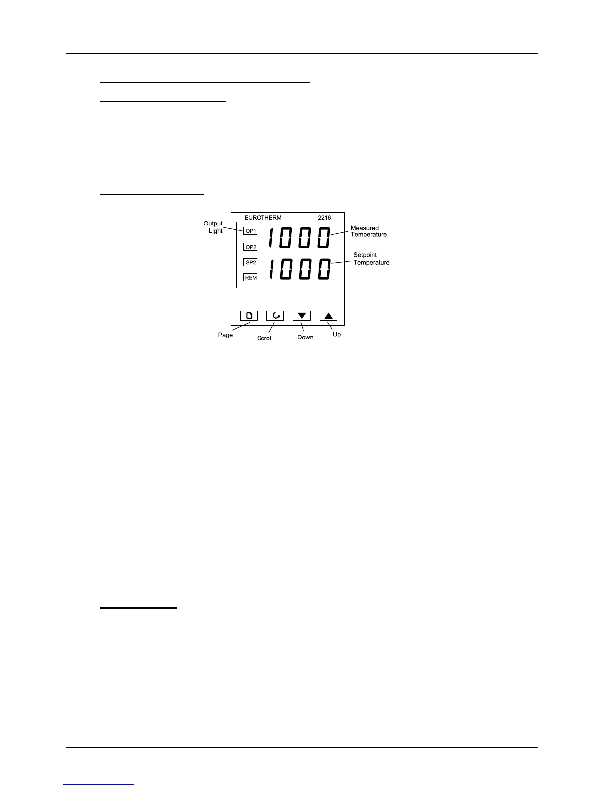
52132 &2116 –OPERATION
When switched on, the controller lights up, goes through a short test routine, and then displays
the measured temperature or the overtemperature setpoint.
The Page key allows access to parameter lists within the controller; most lists and parameters
are hidden and cannot be accessed by the operator because they contain factory-set parameters
which should not be changed.
A single press of the page key displays the temperature units, normally set to °C; further
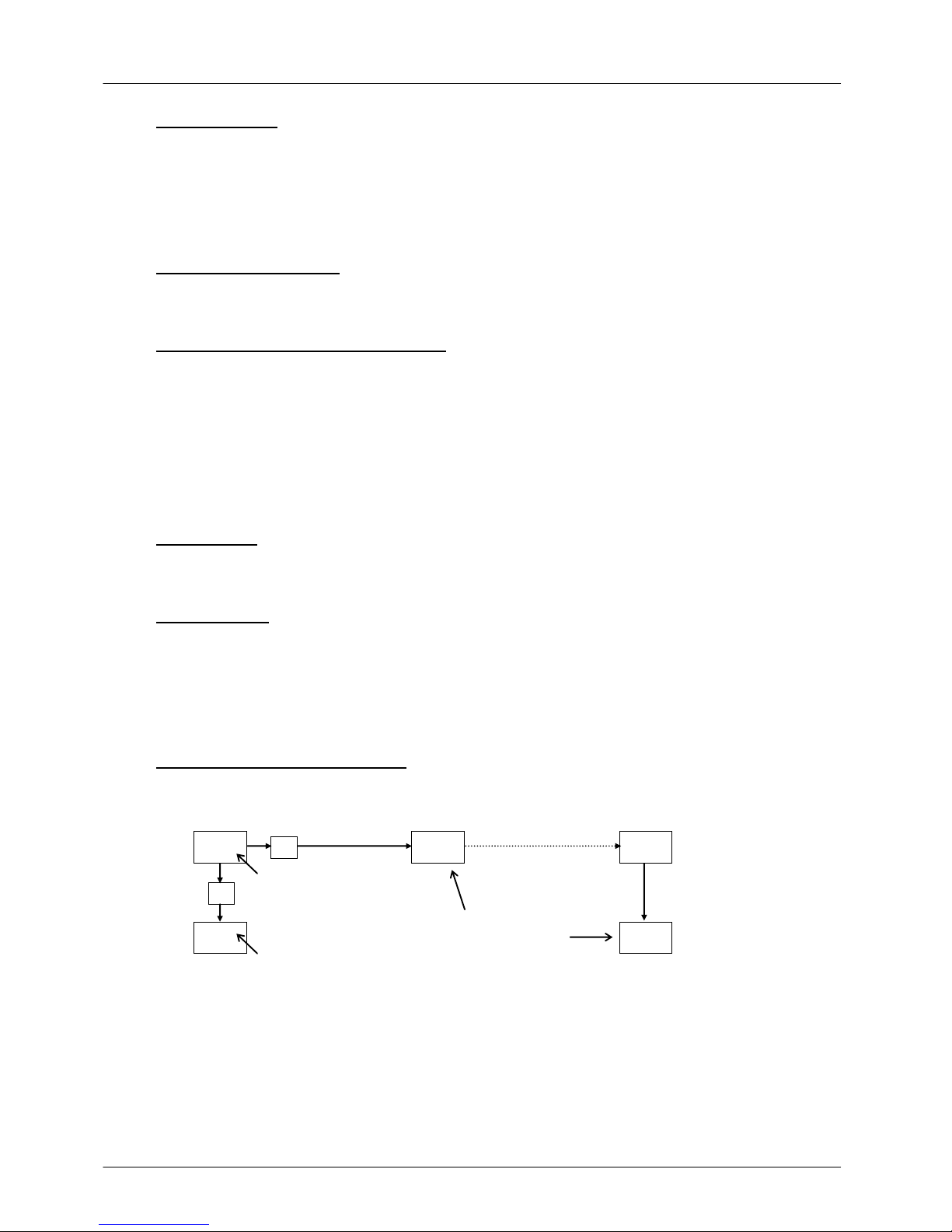
presses reveal the lists indicated in the Navigation Diagram in section 5.6.
The Scroll key allows access to the parameters within a list. Some parameters are display-
only; others may be altered by the operator.
A single press of the scroll key in the Home list displays the temperature units; further presses
reveal the parameters in the current list indicated in the Navigation Diagram.
To return to the Home list at any time, press Page and Scroll together, or wait for 45
seconds.
The Down and Up keys are used to alter the setpoint or other parameter values.
2132 2116

2132/2116 Overtemperature Controller
MC11 –1.05 7
5.1 Basic Operation
Use Down and Up to alter the overtemperature setpoint. This should normally be set a
little above the maximum working temperature (say 15°C above). The unit is supplied at 15°C
above the furnace or oven maximum working temperature.
Press Scroll to view the present temperature as seen by the overtemperature controller. Press it
twice, because the first press shows the temperature units (°C).
5.2 Overtemperature Alarm
If an overtemperature condition occurs, the OP2 indicator flashes, and an alarm message 2FSH
also flashes, alternating with the setpoint. Power to the heating elements is disconnected.
5.3 Resetting the Overtemperature Alarm
To acknowledge the alarm press Scroll and Page together.
If the alarm is acknowledged while there is still an overtemperature condition, the OP2 indicator
stops flashing but continues to glow. The 2FSH alarm continues to flash until the over-
temperature condition is cleared (by the temperature falling), when normal operation resumes.
If the alarm is acknowledged when the temperature has dropped (or after the overtemperature
setpoint has been raised) such that the overtemperature condition no longer exists, then the
furnace or oven immediately resumes normal operation.
5.4 Sensor Break
The overtemperature cut-out system also operates if the overtemperature control thermocouple
breaks or becomes disconnected. The message S.br flashes instead of 2FSH.
5.5 Audible Alarm
If an audible alarm is supplied for use with the overtemperature controller, then it is normally
configured to sound on overtemperature condition, and to stop sounding when the alarm is
acknowledged as given in section 5.3. Note that the alarm may sound during controller start-up.
It is not possible to cover in this manual other possible alarm features which may be included by
customer special order.
5.6 2132 & 2116 Navigation Diagram
Present temperature.
Use
/
to view the
temperature.
Home
List
Access
List
20.0
ACCS
PV
codE
*C
*C
Overtemperature
setpoint. Use
/
to
access setpoint.
for factory access to
lists and parameters
not available to the
operator

Copyright © 2016 Carbolite Gero Limited
Carbolite Gero Limited, Parsons Lane, Hope,
Hope Valley, S33 6RB, England.
Telephone: +44 (0)1433 620011
Fax: +44 (0)1433 621198
E-mail: info@carbolite-gero.com
For preventive maintenance, repair and calibration of
all Furnace and Oven products, please contact:
Carbolite Gero Service
Telephone: +44 (0)1433 624242
Fax: +44 (0)1433 624243
Email: ServiceUK@carbolite-gero.com
MC11 –1.05 01/01/16 2216
This manual suits for next models
2
Table of contents
Popular Temperature Controllers manuals by other brands

netvox
netvox R718EC user manual

Emerson
Emerson Dixell XW30L - CL01 Installing and operating instructions

Saunier Duval
Saunier Duval exacontrol 7 manual

aci
aci BACnet Series Installation & operation instructions

Honeywell
Honeywell C7046C Product data

Sensored Life
Sensored Life MarCELL Pro quick start guide