CARDIN ELETTRONIC 100/SL1524 User manual

1
ITALIANO
ENGLISH
FRANÇAIS
DEUTSCH
ESPAÑOL
ATTENTION! Before installing this device read the
following instructions carefully!
Installation example Page 2-3
Important remarks Page 12
Installation Page 13
Manual opening Page 14
Electronic programmer Page 14
Indications on the display Page 15
Programming procedure Page 16-17
Automatic repositioning Page 17
Remote control Page 18
Function modes Page 18
Battery powered operation Page 19
Standard wiring diagram Page 44
Technical specications Page 46
ATTENTION! Avant de commencer la pose, lire atten-
tivement les instructions!
Exemple d’installation Page 2-3
Consignes importantes Page 20
Instructions pour l’utilisation Page 21
Ouverture manuel Page 22
Programmateur électronique Page 22
Indications de l’afcheur Page 23
Procédé de programmation Page 24-25
Repositionnement automatique Page 25
Commande par radio Page 26
Modes de fonctionnement Page 26
Fonctionnementde à batterie Page 27
Schéma électrique de l'exemple d'installation Page 44
Caractéristiques techniques Page 46
ACHTUNG! Bevor mit der Installation begonnen wird,
sollte die Anleitung aufmerksam gelesen werden.
Anlagenart Seite 2-3
Wichtige Hinweise Seite 28
Installationsanleitung Seite 29
Manuelle Öffnung Seite 30
Elektronischer Steuerung Seite 30
Display-Anzeigen Seite 31
Programmierverfahrung Seite 32-33
Automatische Rückstellung Seite 33
Fernbedienung Seite 34
Funktionsart Seite 34
Batteriebetrieb Seite 35
Elektrischer Schaltplan Anlagenart Seite 44
Technische Eigenschaften Seite 46
¡ATENCIÓN! Antes de iniciar la instalación del sistema,
leer atentamente las instrucciones.
Instalación estándar Página 2-3
Advertencias importantes Página 36
Instrucciones para la instalación Página 37
Apertura manuella Página 38
Programador electrónico Página 38
Indicaciones en el display Página 39
Procedimiento para la programación Página 40-41
Reposicionamiento automatico Página 41
Mando vía radio Página 42
Modalidad de funcionamiento Página 42
Funcionamiento por batería Página 43
Esquema eléctrico instalación estándar Página 44
Características técnica Página 46
ZVL427.04 Mod: 22-04-2003
By CARDIN ELETTRONICA spa
Via Raffaello, 36
31020 San Vendemiano (TV) Italy
Tel: +39/0438.401818
Fax: +39/0438.401831
email (Italy): Sales.office.it@cardin.it
email (Europe): Sales.office@cardin.it
Http: www.cardin.it
100/SL1524
CODE MODEL
ZVL427.04 SL 1524
SERIES DATE
18-03-2003
Questo prodotto è stato testato e collaudato nei laboratori della casa costruttrice, la quale ne ha vericato la
perfetta corrispondenza delle caratteristiche con quelle richieste dalla normativa vigente.
This product has been tried and tested in the manufacturer's laboratory who have veried that the product
conforms in every aspect to the safety standards in force.
Ce produit a été testé et essayé dans les laboratoires de la Maison Constructrice qui a pris soin de vérier la
conformité de ses caractéristiques avec les exigences des normes en vigueur.
Dieses Produkt wurde in den Werkstätten der Herstellerrma auf die perfekte Übereinstimmung ihrer
Eigenschaften mit den von den geltenden Normen vorgeschriebenen getestet und geprüft.
Este producto ha sido probado y ensayado en los laboratorios del fabricante, que ha comprobado la perfecta
correspondencia de sus caracteristicas con las que dispone la normativa vigente.
AUTOMAZIONE PER CANCELLI SCORREVOLI CON MOTORE IN CORRENTE CONTINUA
AUTOMATION FOR SLIDING GATES WITH A DC POWERED MOTOR
AUTOMATISME POUR PORTAILS COULISSANTS AVEC MOTEUR À COURANT CONTINU
AUTOMATISIERUNG FÜR SCHIEBETORE MIT GLEICHSTROMMOTOR
AUTOMATIZACIÓN PARA CANCELAS CORREDERAS CON MOTOR DE CORRIENTE CONTINUA
ATTENZIONE! Prima di iniziare l'installazione leggere
le istruzioni attentamente!
Impianto tipo Pagina 2-3
Avvertenze importanti Pagina 4
Istruzioni per l'installazione Pagina 5
Apertura manuale Pagina 6
Programmatore elettronico Pagina 6
Indicazioni del display Pagina 7
Procedura di programmazione Pagina 8-9
Riposizionamento automatico Pagina 9
Comando via radio Pagina 10
Modalità di funzionamento Pagina 10
Funzionamento a batteria Pagina 11
Schema elettrico impianto tipo Pagina 44
Caratteristiche tecniche Pagina 46
ENGLISH

2
SCALA:
Prodotti Technocity
SL
24-05-99
DI0128 Description :
Product Code :
Date :
Drawing number :
P.J.Heath
CARDIN ELETTRONICA S.p.A - 31020 San Vendemiano (TV) Italy - via Raffaello, 36 Tel: 0438/401818 Fax: 0438/401831
Draft :
All rights reserved. Unauthorised copying or use of the information contained in this document is punishable by law
IMPIANTO A NORME STRUTTURA SL
H
I
L
M
B
F
D
B
N
P
A
C
G
O
A
G
Q
O
C
D
E
30-40 mm
VERIFICHE PRELIMINARI - PRELIMINARY CHECKS - CONTRÔLES À EFFECTUER AVANT LE MONTAGE
VORKONTROLLEN - PRUEBAS PREVIAS
LEGENDA
A Supercie anta cancello
B Distanza tra parti sse e mobili
C Guida di scorrimento
D Distanza di sicurezza
E Arresto meccanico in chiusura
F Elemento elastico deformabile
G Recinzione
H Distanza tra recinzione e cancello
I Rete o griglia
L Traforato metallico
M Sfera di prova passaggio
N Livella a bolla
O Pattini o rulli guida
P Corsa cancello
Q Arresto meccanico in apertura
LEGENDA
A Gate surface
B Distance between the xed part and the moving parts
C Castor guide
D Safety distance
E Closing mechanical travel limit
F Rubber anticrush buffer
G Fencing
H Distance between the fence and the gate
I Wire mesh
L Punched metal plate
M Test sphere
N Spirit level
O Runner guide
P Gate travel distance
Q Opening mechanical travel limit
NOMENCLATURE
A Surface vantail du portail
B Distance entre parties xes et mobiles
C Rail de guidage
D Distance de sécurité
E Butée en fermeture
F Élément élastique déformable
G Clôture
H Distance entre clôture et portail
I Grillage ou grille
L Panneau métallique perforé
M Bille d'essai de passage
N Niveau à bulle
O Patins ou galets de guidage
P Course portail
Q Butée en ouverture
ZEICHENERKLÄRUNG
A Torügeloberäche
B Abstand zwischen festen und beweglichen Teilen
C Gleitschiene
D Sicherheitsabstand
E mechanischer Anschlag bei Schliessung
F Verformbares elastisches Element
G Gitter
H Abstand zwischen Gitter und Torügel
I Drahtgeecht oder Gitterwerk
L Lochblech
M Prüfkugel
N Wasserwaage
O Gleitschuhe oder Führungsrollen
P Torügellaufstrecke
Q Mechanischer Endanschlag bei Öffnung
LEYENDA
A Supercie cancela
B Distancia entre piezas jas y móviles
C Guía de deslizamiento
D Distancia de seguridad
E Tope mecánico en fase de cierre
F Elemento elástico deformable
G Cercado
H Distancia entre cercado y cancela
I Red de alambre o verja
L Elemento metálico agujereado
M Bola de prueba paso
N Nivel de burbuja
O Patines o rodillos de guía
P Carrera cancela
Q Tope mecánico en fase de apertura
1

3
9
TX
2x1+RG58
230V - 50Hz
RX
4x1
2x1
3x1
2x1
4x1
2x1,5+T
SCALA: 1:2
prodotti Technocity (lamp. fotocellule ecc.)
SL1524
04-02-2002
DI0235 Description :
Product Code :
Date :
Drawing number :
P.J.Heath
CARDIN ELETTRONICA S.p.A - 31020 San Vendemiano (TV) Italy - via Raffaello, 36 Tel: 0438/401818 Fax: 0438/401831
Draft :
All rights reserved. Unauthorised copying or use of the information contained in this document is punishable by law
INSTALLAZIONE TIPO SL1524
TX
RX
6
5
7
1
2
4
3
8
LEGENDA
1 Motoriduttore
2 Fotocellula interna
3 Fotocellula esterna
4 Selettore a chiave
5 Lampeggiatore
6 Interruttore onnipolare con apertura contatti min. 3mm
7 Costa sensibile
8 Cremagliera
9 Antenna esterna (Cavo coassiale RG58 Impedenza 50Ω)
LEGEND
1 Geared motor
2 Internal photelectric cells
3 External photelectric cells
4 Mechanical selector switch
5 Flashing warning lights
6 All pole circuit breaker with a minimum gap of 3mm between the contacts
7 Contact safety buffer
8 Toothed rack
9 External antenna (RG58 coaxial cable with an impedance of 50Ω)
NOMENCLATURE
1 Motoréducteur
2 Cellule photoélectrique intérieure
3 Cellule photoélectrique extérieure
4 Sélecteur à clé
5 Clignoteur
6 Interrupteur omnipolaire avec ouverture des contacts d'au moins 3mm.
7 Bord de sécurité
8 Crémaillère
9 Antenne externe (Câble coaxial RG58 - Impédance 50Ω)
IMPIANTO TIPO - INSTALLATION EXAMPLE - EXEMPLE D'INSTALLATION - ANLAGENART - INSTALACIÓN ESTÁNDAR
2
ZEICHENERKLÄRUNG
1 Getriebemotor
2 Interne Lichtschranke
3 Externe Lichtschranke
4 Schlüsseltaster
5 Blinklicht
6 Allpoliger Schalter mit Kontaktenabstand von mindestens 3mm.
7 Kontaktleiste
8 Zahnschiene
9 Externe Antenne (Koaxialkabel RG58 Impedanz 50Ω
)
LEYENDA
1
Motorreductor
2 Fotocélula interior
3 Fotocélula exterior
4 Selector con llave
5 Luz intermitente
6 Interruptor omnipolar con apertura entre los contactos de 3mm. como mínimo.
7 Borde sensible
8 Cremallera
9 Antena exterior (RG58 impedancia 50Ω)

4
• Il presente manuale si rivolge a persone abilitate all'installazione di "APPA-
RECCHI UTILIZZATORI DI ENERGIA ELETTRICA" (ai sensi della legge N.46
del 5.3.1990) e richiede una buona conoscenza della tecnica, esercitata in
forma professionale e della normativa vigente. I materiali usati devono essere
certicati e risultare idonei alle condizioni ambientali di installazione.
• Le apparecchiature qui descritte dovranno essere destinate solo all'uso per il
quale sono state espressamente concepite:
"La motorizzazione di cancelli e portoni".
L’utilizzo dei prodotti e la loro destinazione ad usi diversi da quelli previsti e/o
consigliati, non è stata sperimentata dal costruttore, pertanto i lavori eseguiti
sono sotto la completa responsabilità dell’installatore. Il costruttore non
risponde qualora l'impianto elettrico non risulti conforme alle norme vigenti
ed in particolare qualora il circuito di protezione (terra) non sia efciente.
• Il programmatore è dotato di un controllo sulla corrente assorbita dal motore,
utilizzato per bloccare il moto in condizioni di emergenza; tale controllo non
viene però fatto:
- nei primi 5 sec. della fase di apertura da completamente chiuso
- nei 2 secondi iniziali di ogni altro movimento
- quando la batteria è poco carica.
Evitare pertanto di fare resistenza sull’anta in tali fasi, in caso contrario
potrebbe saltare il fusibile "F1" del circuito motore.
Attenzione! La presenza del sensore di corrente non elimina l’obbligo
di installare le fotocellule o altri dispositivi di sicurezza previsti dalle
normative vigenti.
• Dopo aver installato il dispositivo, e prima di dare tensione alla centralina,
vericare che il movimento dell’anta eseguito in modo manuale (con motore
sbloccato) non abbia punti di resistenza particolarmente marcata.
Attenzione!
È assolutamente obbligatoria la presenza
delle battute antideragliamento.
Il programmatore ha la facoltà di attivare automaticamente
il motore: Questo viene segnalato da un prelampeggio di 10
secondi, e dall'indicazione sul display ("riposizionamento
automatico" a pagina 9).
Nota: Nel caso si debba vericare lo stato del fusibile "F2", scollegare prima l'ali-
mentazione dal programmatore; ripristinarla solo dopo aver inserito il fusibile.
Attenzione! Il motoriduttore è assemblato in fabbrica per essere
installato a sinistra del cancello. Leggere con attenzione il paragrafo
a pag. 6 "Istruzioni sul posizionamento del gruppo".
Attenzione! Per il corretto funzionamento del programmatore è
necessario che le batterie incorporate siano in buono stato: in
assenza di tensione di rete, se le batterie sono scariche, si verica
la perdita del controllo della posizione dell'anta con conseguente
segnalazione di allarme.
Controllare quindi l'efcienza delle batterie ogni sei mesi. (vedi pagina
11 "Verica delle batterie").
Caratteristiche generali
Questo prodotto è stato progettato e fabbricato in tutte le sue parti a cura della
Cardin Elettronica la quale ne ha vericato la perfetta corrispondenza delle
caratteristiche con quelle richieste dalla normativa vigente.
Q
Possibilità d'impiego
Il gruppo 100/SL1524 movimenta cancelli scorrevoli no a 1500 Kg peso anta.
Descrizione tecnica
- Alimentazione generale 230Vac
- Motore alimentato con tensione max 37Vdc.
- Carter superiore e carter inferiore in materiale plastico antiurto ad alta resi-
stenza.
- Cassa del riduttore in alluminio pressofuso. All'interno opera un sistema di
riduzione a vite senza ne a doppia riduzione con lubricazione a grasso uido
permanente.
- Sistema di riduzione irreversibile con sblocco manuale a chiave.
- Programmatore elettronico incorporato completo di parte di potenza, logica di
controllo, carica batterie e decodica per sistema radio ricevente. L’alimentazione
viene fornita alla scheda da un trasformatore toroidale separato, alloggiato
nello stesso contenitore e collegato alla scheda tramite Faston.
- Il sistema è dotato di controllo elettronico in frenata, riducendo al minimo gli
urti di arresto dovuti all'inerzia del cancello.
Accessori
106/SLOPC - Cremagliera in bra di vetro 20 x 20 con asole sopra
106/SLOPC1 - Cremagliera in bra di vetro 20 x 20 con asole sotto
950/XLBS03 - Prolo in gomma H60 + supporto alluminio
950/XLBS1 - Pressostato per costa sensibile. Collegato ad un prolo in gomma
chiuso, traduce un comando pneumatico in un comando elettrico che può essere
interpretato dalla centralina come un comando d'inversione. Completo di tubetto
essibile Ø6x1, lungh. 1m e tubetto raccordo per il collegamento con il prolo in
gomma chiuso.
È responsabilità dell’installatore vericare le seguenti condizioni di sicurezza:
1. L’installazione deve essere sufcientemente lontana dalla strada in modo da
non costituire pericolo per la circolazione.
2. Il motore deve essere installato all’interno della proprietà ed il cancello non
deve aprirsi verso l’area pubblica.
3. Il cancello motorizzato è principalmente adibito al passaggio di vetture. Dove
possibile installare per pedoni un ingresso separato.
4. I comandi devono essere posti in vista, ma non entro il raggio d’azione del
cancello. Inoltre quelli installati all’esterno devono
essere protetti da una sicurezza tale da prevenire
l’uso non autorizzato.
5. È buona norma segnalare l’automazione con targhe di
avvertenza (simili a quella in gura) che devono essere
facilmente visibili.
Qualora l’automazione sia adibita al solo passaggio di
veicoli dovranno essere poste due targhe di avvertenza
di divieto di transito pedonale (una all’interno, una
all’esterno).
6. Rendere consapevole l’utente che bambini o animali
domestici non devono giocare o sostare nei pressi del cancello. Se necessario
indicarlo in targa.
7. Per qualsiasi dubbio a riguardo della sicurezza dell’installazione, non procedere
ma rivolgersi al distributore del prodotto.
AVVERTENZE IMPORTANTI AVVERTENZE IMPORTANTI AVVERTENZE IMPORTANTI
LEGGERE ATTENTAMENTE LE SEGUENTI AVVERTENZE PRIMA DI PROCEDERE ALL’INSTALLAZIONE.
PRESTARE PARTICOLARE ATTENZIONE A TUTTE LE SEGNALAZIONI DISPOSTE NEL TESTO. IL MAN-
CATO RISPETTO DI QUESTE POTREBBE COMPROMETTERE IL BUON FUNZIONAMENTO DEL SISTEMA.
SCALA: 1:2
Prodotti Technocity
SL1524
06-02-2002
DI0236 Description :
Product Code :
Date :
Drawing number :
P.J.Heath
CARDIN ELETTRONICA S.p.A - 31020 San Vendemiano (TV) Italy - via Raffaello, 36 Tel: 0438/401818 Fax: 0438/401831
Draft :
All rights reserved. Unauthorised copying or use of the information contained in this document is punishable by law
Dimensioni d'ingombro
360
330
240
65
25
5
117
165 165
3
DIMENSIONI D'INGOMBRO
CONSIDERAZIONI GENERALI DI SICUREZZA
APERTURA AUTOMATICA
NON AVVICINARSI
NON PERMETTE A BAMBINI O AD
ANIMALI DOMESTICI DI SOSTARE NEL
RAGGIO D'AZIONE DEL CANCELLO
ATTENZIONE

5
SCALA: 1:2
Prodotti Technocity
SL1524
08-02-2002
DI0240 Description :
Product Code :
Date :
Drawing number :
P.J.Heath
CARDIN ELETTRONICA S.p.A - 31020 San Vendemiano (TV) Italy - via Raffaello, 36 Tel: 0438/401818 Fax: 0438/401831
Draft :
All rights reserved. Unauthorised copying or use of the information contained in this document is punishable by law
VISTA DI FIANCO CON MOTORE
50 15
2 mm
SCALA: 1:2
Prodotti Technocity
SL1524
08-02-2002
DI0239 Description :
Product Code :
Date :
Drawing number :
P.J.Heath
CARDIN ELETTRONICA S.p.A - 31020 San Vendemiano (TV) Italy - via Raffaello, 36 Tel: 0438/401818 Fax: 0438/401831
Draft :
All rights reserved. Unauthorised copying or use of the information contained in this document is punishable by law
VISTA DI FIANCO SENZA MOTORE
50
110
104,5
50
SCALA: 1:2
Prodotti Technocity
SL1524
06-02-2002
DI0238 Description :
Product Code :
Date :
Drawing number :
P.J.Heath
CARDIN ELETTRONICA S.p.A - 31020 San Vendemiano (TV) Italy - via Raffaello, 36 Tel: 0438/401818 Fax: 0438/401831
Draft :
All rights reserved. Unauthorised copying or use of the information contained in this document is punishable by law
VISTA CONTROPIASTRA SL1524
69
4
3
2
1
34
SCALA: 1:2
Prodotti Technocity
SL1524M
30-01-2002
DI0237 Description :
Product Code :
Date :
Drawing number :
P.J.Heath
CARDIN ELETTRONICA S.p.A - 31020 San Vendemiano (TV) Italy - via Raffaello, 36 Tel: 0438/401818 Fax: 0438/401831
Draft :
All rights reserved. Unauthorised copying or use of the information contained in this document is punishable by law
CONTROPIASTRA SL1524M
M10
50 mm
312
31
54 34
157
69
43
Importante: Il motoriduttore può essere posizionato sia alla sinistra che alla destra
della luce passaggio. Vedere paragrafo "ISTRUZIONI SUL POSIZIONAMENTO
DEL GRUPPO". Individuata l'esatta posizione, procedere come segue:
Ancoraggio del motoriduttore (g. 4, 5, 6)
- Preparare una piazzola in cemento in cui sia inserita la piastra di base
"3", con annesse le zanche di ancoraggio, da cui dovranno emer-
gere i tubi essibili per il passaggio dei cavi elettrici "4", utilizzando
l'apposita apertura, e quattro gambi filettati M10, sporgenti 50mm.
- La piastra dovrà risultare perfettamente in bolla, pulita in tutta la sua supercie
e con i letti M10 emergenti perpendicolarmente dalla piastra e perfettamente
puliti.
Nota: È preferibile che la piazzola sporga dal livello terra di circa 50mm. Questo
per evitare che accumuli d'acqua possano danneggiare l’apparecchia-
tura. Se la guida di scorrimento è già esistente, la piazzola di cemento
deve essere ricavata in parte anche nel getto di fondazione della guida
stessa. Tale accorgimento elimina la possibilità che le due strutture
cedano in modo diverso.
- Svitare i quattro dadi M10 sui quattro gambi
lettati (precedentemente utilizzati per bloccare
le zanche) dalla piastra di base.
- Posizionare il motoriduttore sui quattro gambi
lettati e farlo appoggiare sulla contropiastra
- Renderlo quindi solidale alla base utilizzando
quattro rondelle e altrettanti dadi in dotazione,
curando che il gruppo rimanga in bolla e sia
perfettamente stabile.
- Regolare l'altezza del gruppo utilizzando i quattro
grani presenti sul motore.
Questo accorgimento per-
metterà tutte le regolazioni
successive alla posa.
Montaggio cremagliera
- sbloccare il motoriduttore (g.
8), appoggiare il primo elemento
di cremagliera sul pignone e
ssarlo all'anta.
Poi spostando l'anta pro-
cedere così con gli altri ele-
menti di cremagliera per tutta
la lunghezza dell'anta.
- ultimato il fissaggio della
cremagliera, regolare il gioco
pignone-cremagliera (1-2mm)
agendo sui grani posti alla base
del motoriduttore; in modo che
il peso dell’anta non vada a
gravare sul gruppo, cosa che
non deve mai succedere.
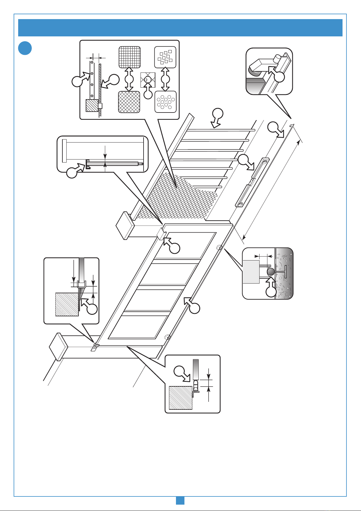
Prima di procedere all'esecuzione dell'impianto vericare che la struttura da
automatizzare sia in perfetta efcienza nelle sue parti sse e mobili e realizzata
in conformità alla normativa vigente. A tal ne accertarsi che:
- La supercie dell’anta scorrevole "A" sia liscia e senza sporgenze, no
all’altezza di 2.5m dal suolo. Possono intendersi liscie anche sporgenze dalla
supercie no a 3mm purché con bordi arrotondati. Se la supercie dell’anta
non è liscia, tutta la sua altezza, no al limite di 2.5m dal suolo, dovrà essere
protetta con i seguenti dispositivi:
a) Fotocellule
b) Costa sensibile
- tra le parti sse e scorrevoli non vi deve essere una distanza "B" maggiore di
15mm.
- la guida di scorrimento "C", preferibilmente di sezione tonda, deve essere
ssata al suolo in modo stabile e indeformabile, completamente esposta e
priva di imperfezioni che possano ostacolare il movimento del cancello.
- a cancello chiuso deve restare uno spazio libero "D", per tutta l’altezza della
parte anteriore del cancello, di almeno 50mm mentre la battuta meccanica
"E" di ne corsa in chiusura deve essere posta sulla parte superiore del can-
cello.
- lo spazio libero "D" può essere ricoperto da un elemento elastico deformabile
"F" o meglio da una costa di sicurezza.
- se durante il movimento di apertura, il cancello scorre vicino ad una cancellata
"G" ad elementi verticali o con luci libere provvedere all’installazione di una
protezione adeguata secondo il caso:
1. Distanza "H" maggiore di 500mm: nessuna protezione;
2. Distanza "H" compresa tra 500 e 300mm: applicazione di una rete "I" o di un
traforato metallico "L" avente aperture che non permettano il passaggio di una
sfera "M" del diametro di 25mm;
3. Distanza "H" minore di 300mm: applicazione di una rete "I" o di un traforato
metallico "L" aventi aperture che non permettano il passaggio di una sfera "M"
del diametro di 12mm. I li delle reti "I" non devono avere sezione minore di
2,5mm2 e i traforati metallici "L" non devono avere spessore minore di 1,2mm.
Oltre il limite di 2,5m dal suolo per il tratto "P" di scorrimento del cancello tali
protezioni non sono necessarie.
- vericare lo stato di usura di eventuali parti vecchie, consumate del cancello
e se necessario provvedere alla loro sostituzione e lubricazione.
- vericare la messa in bolla "N" della guida.
- i pattini o rulli di guida superiori "O" devono presentare un giusto gioco allo
scorrimento dell’anta e in nessun caso ostacolare la sua corsa.
- vericare l’esistenza, assolutamente necessaria, di una battuta di arresto
meccanico in apertura in corrispondenza della massima corsa "P", tale da
garantire la stabilità del cancello e quindi di evitare il pericolo di sgancio dalle
guide.
Attenzione! È comunque cura dell’installatore vericare i punti cri-
tici, di pericolo, e prendere gli opportuni provvedimenti ai ni della
sicurezza e dell’incolumità personale (analisi dei rischi).
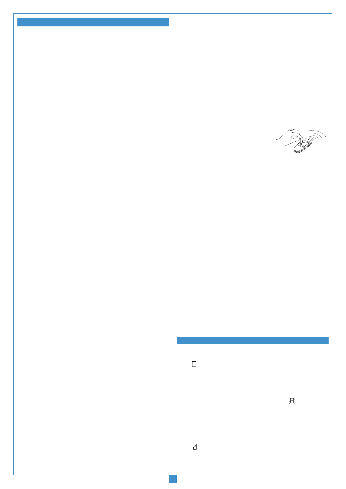
AVVERTENZE PER L'UTENTE
Prima di eseguire qualsiasi operazione di pulizia o di manutenzione, disinserire
l'apparecchiatura dalla rete di alimentazione elettrica, staccare l'alimentazione
del motore e scollegare le batterie.
I comandi minimi che possono essere installati sono APERTURA-STOP-CHIU-
SURA, tali comandi devono essere posti in un luogo non accessibile a bambini
o minori.
Durante la manovra si deve controllare il movimento e azionare il dispositivo di
arresto immediato (STOP) in caso di pericolo. Nell’uso normale si consiglia di
aspettare la completa apertura del cancello prima di attraversarlo.
In caso di mancanza di energia elettrica e con la batteria scarica il cancello può
essere sbloccato manualmente utilizzando l'apposita chiave di sblocco in dota-
zione (vedi sblocco manuale g. 8). Controllare periodicamente lo stato di usura
dei perni ed eventualmente ingrassare le parti in moto (perni, cremagliera ecc),
usando lubricanti che mantengano uguali caratteristiche di attrito nel tempo e
adatti a funzionare tra -20 e +55°C.
In caso di guasto o anomalie di funzionamento staccare l'alimentazione elettrica a
monte dell'apparecchiatura, staccare le batterie e chiamare l'assistenza tecnica.
Le eventuali riparazioni devono essere eseguite da personale specializzato usando
materiali originali e certicati. L'uso dell'automazione non è idoneo all'azionamento
in continuo, bensì deve essere contenuto al 70%.
N.B: L’impianto appena installato e certicato è sicuramente rispondente alle
norme però sarà cura dell’utilizzatore mantenerlo efciente nel tempo. Si consi-
glia pertanto di chiedere una visita di controllo da parte di personale qualicato
almeno una volta all’anno.
ISTRUZIONI PER L’USO
VERIFICHE PRELIMINARI (fig.1, pag.2) ISTRUZIONI PER L’INSTALLAZIONE
4
5
6

6
SL1524
03-04-2003
DI0282 Description :
Product Code :
Date :
Drawing number :
P.J.Heath
CARDIN ELETTRONICA S.p.A - 31020 San Vendemiano (TV) Italy - via Raffaello, 36 Tel: 0438/401818 Fax: 0438/401831
Draft :
All rights reserved. Unauthorised copying or use of the information contained in this document is punishable by law
Morsettiera 230Vac
Scala 1:1
L
N
- Il motoriduttore è assemblato in fabbrica per essere installato a SINISTRA del
cancello (visto dall’interno). Per l'installazione a DESTRA agire sul parametro
di programmazione numero "9".
L'operazione di sblocco va fatta a motore fermo. Per sbloccare l'anta del cancello
munirsi della chiave in dotazione all'apparecchiatura. Essa deve essere conservata
in luogo di facile reperimento.
Operazione di sblocco
1. Ruotare il disco di protezione serratura sulla manopola
di sblocco, inserire la chiave e ruotarla di mezzo giro in
senso antiorario. La manopola è libera di sbloccare.
2. Ruotare la manopola di 90° in senso orario. Il riduttore
è sbloccato ed il cancello è libero di scorrere manual-
mente;
Ribloccaggio
1. Ruotare la manopola in senso antiorario e riportarla nella posizione
di blocco.
2. Riarmare il blocco riduttore:
- elettricamente dando un impulso di apertura oppure chiusura.
- manualmente spostando leggermente l'anta.
3. Ruotare la chiave in senso orario e ribloccare la manopola.
A sistema ripristinato riporre la chiave in un luogo sicuro
Attenzione! Non usare lo sblocco durante il normale funzionamento
del cancello. Se si sblocca il cancello e poi si dà un comando di
moto sul display apparirà il simbolo .
Accesso al quadro di comando
Attenzione! Prima di accedere al quadro di
comando assicurarsi di aver disinserito l’interruttore
generale a monte dell’apparecchiatura.
Per accedere al motore allentare le due viti "A"
poste alle estremità laterali del coperchio come
indicato in gura 9.
Programmatore per motore in corrente continua con ricevente incorporata, che
permette la memorizzazione di 300 codici utente (vedere "comando via radio",
a pag.10). La decodica è di tipo 'rolling code', e la frequenza di funzionamento
è di 433.92 MHz.
La velocità di rotazione dei motori è controllata elettronicamente, con partenza
lenta e successivo incremento; la velocità viene ridotta con anticipo rispetto
all'arrivo in battuta, in modo da ottenere un arresto controllato.
La programmazione, eseguibile mediante due soli pulsanti, permette la congu-
razione del sistema, del sensore di sforzo e della corsa totale dell'anta.
La logica esegue un controllo di posizione tramite encoder.
L’intervento del sensore antischiacciamento/anticonvogliamento causa una breve
(10 cm) inversione del moto e poi il blocco.
COLLEGAMENTO ELETTRICO
Aprire lo "Schema elettrico impianto tipo" piegato all'interno dell'ultima pagina
del presente libretto e procedere con il collegamento elettrico.
B1 Buzzer segnalazione modalità "via radio"
CN1 Connessione Faston secondario 24Vac alimentazione logica
CN2 Connessione Faston secondario alimentazione circuito motore
V2:0Vac, V3:20Vac, V4:30Vac
CN3 Connessione Faston batteria
CN4 Connessione Faston motore
D1 Display a 7 segmenti
E1 Connettore encoder
F1 Fusibile a lama(1) 15A (protezione alimentazione motore)
F2 Fusibile a lama(1) 4A (protezione circuito 24V)
SCALA: 1:2
Prodotti Technocity
SL1524
07-02-2002
DI0242 Description :
Product Code :
Date :
Drawing number :
P.J.Heath
CARDIN ELETTRONICA S.p.A - 31020 San Vendemiano (TV) Italy - via Raffaello, 36 Tel: 0438/401818 Fax: 0438/401831
Draft :
All rights reserved. Unauthorised copying or use of the information contained in this document is punishable by law
Sblocco motore
F3 Fusibile a lama(1) 15A (protezione motore modalità batteria)
F4 Fusibile a lama(1) 4A (protezione circuito 24V modalità batteria)
J1 Jumper selezione canale radio
J2 Jumper abilitazione alla memorizzazione codici Tx via radio
J3 Jumper selezione funzione "Uomo presente"
L1 LED di alimentazione scheda
L2 LED di errata connessione batteria
L3 LED di batteria sotto carica
L4 LED di segnalazione modalità uomo presente
L5 LED di programmazione codici trasmettitore
L6 LED di segnalazione tasto di blocco
L7 LED di segnalazione fotocellule di stop
L8 LED di segnalazione fotocellule d'inversione
M1 Modulo di memoria
P1 Tasto di programmazione (PROG)
P2 Tasto di selezione (SEL)
P3 Tasto di cancellazione codice TX (DEL)
P4 Tasto di memorizzazione codice TX (MEMO)
R1 Modulo RF, 433 MHz per trasmettitore S449
T1 Trimmer di regolazione della tensione di carica della batteria
LP Lampeggiatore
LS Lampada spia
FTC-RX Fotocellula ricevitore
FTC-TX Fotocellula trasmettitore
PS Pressostato per costa sensibile
SEL Selettore a chiave
TB Tasto di blocco
ANS Antenna esterna 433 MHz
• Accertarsi, prima di eseguire il collegamento elettrico, che la tensione
e la frequenza riportate sulla targhetta caratteristiche corrispondano a
quelle dell'impianto di alimentazione.
• Tra la centralina di comando e la rete deve essere interposto un interrut-
tore onnipolare, con distanza di apertura tra i contatti di almeno 3mm.
• Non utilizzare cavo con conduttori in alluminio; non stagnare l’estremità
dei cavi da inserire in morsettiera; utilizzare cavo con marcatura T min 85°C
resistente agli agenti atmosferici.
• I conduttori dovranno essere adeguatamente ssati in prossimità
della morsettiera in modo che tale ssaggio serri sia l’isolamento che il
conduttore (è sufciente una fascetta).
COLLEGAMENTO ALIMENTAZIONE GENERALE
• Collegare i li di comando e quelli provenienti dalle sicurezze.
• Portare l'alimentazione generale alla morsettiera separata a tre vie passando
prima attraverso il pressacavo posizionato in
basso a destra rispetto al circuito principale:
- collegare il neutro al morsetto N
- collegare la terra al morsetto
- collegare la fase al morsetto L
Collegamenti morsettiera
1 Comune per tutti gli ingressi/uscite
2 Uscita alimentazione carichi esterni 24Vdc(2)
3 Comune per tutti gli ingressi/uscite
4 Uscita alimentazione carichi esterni controllati 24Vdc(2)
5 Comune per tutti gli ingressi/uscite
6 LS uscita lampada spia 24Vdc 3W
7 Comune per tutti gli ingressi/uscite
8 LP uscita lampeggiante 24Vdc
25W con attivazione intermittente (50%), 12,5W con attivazione ssa
9-10 Comune per tutti gli ingressi/uscite
11 FTC_I (N.C.) ingresso per dispositivi di sicurezza (fotocellula di inversione in
chiusura). L'apertura del contatto, conseguente all'intervento dei dispositivi
di sicurezza, durante la fase di chiusura, attuerà l'inversione di moto
12 FTC_S (N.C.) ingresso per dispositivi di sicurezza (fotocellula di stop/costa
pneumatica).
13 Comune per tutti gli ingressi/uscite
14 TB (N.C.) ingresso pulsante di blocco (all'apertura del contatto si interrompe
il ciclo di lavoro no ad un nuovo comando di moto)
15 TC (N.A.) ingresso pulsante di chiusura
16 TA (N.A.) ingresso pulsante di apertura
17 Massa antenna ricevitore radio
18 Centrale antenna ricevitore radio (nel caso si utilizzi un antenna esterna
collegarla con cavo coassiale RG58 imp. 50Ω)
Tutti i contatti N.C. non utilizzati vanno ponticellati e di conseguenza disabilitati i
test sulle sicurezze corrispondenti (FTC_S, FTC_I). Se si vuole attivare il test sulle
FTC_S, FTC_I sia la parte trasmittente che la parte ricevente di tale sicurezze
vanno collegate ai carichi controllati (CTRL24Vdc). Si tenga presente che nel
caso sia abilitato il test, tra la ricezione del comando e il moto dell’anta passa
circa 1 secondo.
Nota (1): i fusibili a lama sono di tipo automotive
Nota (2): la somma delle due uscite per carichi esterni non deve superare 10W.
SCALA: 1:2
Prodotti Technocity
SL1524
07-02-2002
DI0243 Description :
Product Code :
Date :
Drawing number :
P.J.Heath
CARDIN ELETTRONICA S.p.A - 31020 San Vendemiano (TV) Italy - via Raffaello, 36 Tel: 0438/401818 Fax: 0438/401831
Draft :
All rights reserved. Unauthorised copying or use of the information contained in this document is punishable by law
Sblocco carter
A
SCALA: 1:2
Prodotti Technocity
SL1524
30-02-2000
DI0241 Description :
Product Code :
Date :
Drawing number :
P.J.Heath
CARDIN ELETTRONICA S.p.A - 31020 San Vendemiano (TV) Italy - via Raffaello, 36 Tel: 0438/401818 Fax: 0438/401831
Draft :
All rights reserved. Unauthorised copying or use of the information contained in this document is punishable by law
VISTA INTERNA CANCELLO SL1524
APERTURA MANUALE
7
ISTRUZIONI SUL POSIZIONAMENTO DEL GRUPPO
8
9
PROGRAMMATORE ELETTRONICO
DESCRIZIONE SCHEDA ELETTRONICA (g. 10 pagina 44)

7
Alimentare il circuito e vericare che lo stato dei led di segnalazione sia come
segue:
- L1 Led di alimentazione circuito acceso
- L2 Led di errata connessione batteria spento (3)
- L3 Led di batteria sotto carica spento (4)
- L4 Led di segnalazione "uomo presente" spento
- L5 Led di programmazione codici trasmettitori spento
- L6 Led di sicurezza tasto blocco "TB" acceso (5)
- L7 Led di sicurezza fotocellule di stop "FTC_S" acceso (5)
- L8 Led di sicurezza fotocellule d'inversione "FTC_I" acceso (5)
Nota (3): Nel caso sia acceso invertire immediatamente la connessione della
batteria.
Nota (4): Acceso se le batterie sono sotto carica.
Nota (5): Vericare che l'attivazione delle sicurezze porti allo spegnimento del
LED ad esse associato.
Nel caso in cui il LED verde di alimentazione "L1" non si accenda vericare
lo stato dei fusibili ed il collegamento del cavo di alimentazione al primario del
trasformatore.
Nel caso in cui uno o più LED di sicurezza non si accendano vericare che i
contatti delle sicurezze non utilizzate siano ponticellate sulla morsettiera.
Segnalazioni di allarme
Sistema non programmato
È necessario entrare in modalità di programmazione per programmare il
sistema.
Fuori posizione
Nel caso di installazione, è necessario entrare in programmazione per programmare
la corsa dell'anta.
Nel funzionamento normale invece segnala che verrá eseguita la procedura di
riposizionamento automatico (vedi pag. 9). In questo caso qualsiasi comando
ricevuto (TA, TC o TD via radio) da inizio immediatemente a questa procedura.
Attenzione! Il cancello si mette in moto anche senza un comando
Blocco durante la programmazione encoder
Si verica quando viene attivato un contatto N.C. (TB, FTC_I, FTC_S) durante la
programmazione encoder o riposizionamento automatico. Una volta ristabilito lo
stato passivo delle sicurezze l'anta riprende il moto automaticamente.
Errore nel test delle sicurezze
Occorre controllare lo stato delle sicurezze, vericando che vadano in allarme (LED
relativo spento) quando un ostacolo si trova in mezzo al loro raggio di azione.Se si
riscontra un’anomalia sostituire la sicurezza guasta oppure ponticellare l’ingresso
relativo e disabilitare il test relativo alla sicurezza stessa (parametri 7 e/o 8).
Attenzione! Sulle impostazioni dei parametri di sistema la "A" lampeggiante indica
che l'ingresso FTC_S viene usato per la fotocellula di blocco.
Problema sull’alimentazione del motore
Si verica quando il programmatore dà un comando al motore, ma il motore non si
mette in moto. È sufciente controllare le connessioni relative al motore e lo stato
dei fusibili "F1" ed "F3". Dopodiché riprovare a dare un comando di apertura o di
chiusura; se il motore non si dovesse rimettere in moto, allora ci potrebbe essere
un problema meccanico al motore o un problema sulla centralina.
Ricevuto un comando con motore sbloccato
Si verica quando si dà un comando con motore sbloccato. È sufciente ribloccare
il motore (vedi SBLOCCO MANUALE pag.6) e ridare un comando.
Errore sul conteggio encoder
Si è vericato un problema su un segnale o sui segnali relativi all’encoder; vericare
le connessioni relative, riprogrammare il sistema oppure eseguire il riposizionamento
automatico (pag. 9). Se il problema persiste sostituire la scheda encoder.
Errore di direzione encoder
La direzione di marcia dell'anta è diversa da quella stabilita dall'encoder (esempio: il
cancello va in chiusura mentre il programmatore sta eseguendo la fase di apertura).
Controllare la connessione dell'alimentazione motore.
Blocco per batteria scarica
Il programmatore è in blocco a causa dell'esaurimento della carica della batteria
in assenza di tensione di rete. In questa situazione ogni comando ricevuto sarà
ignorato.
Errore di sensore di corrente
Con il motore fermo questo simbolo indica che c'è un problema sul sensore di
corrente.
Errore del motore
Questo simbolo indica che c'è un problema sui relè di controllo del motore.
Segnalazioni di funzionamento
Fase di apertura
Blocco
Pausa per la richiusura automatica (solo se abilitata)
Fase di chiusura
Aggiornamento del sensore di corrente
(solo in programmazione)
Modalità batteria con batteria carica
Modalità batteria con batteria poco carica
INDICAZIONI DEL DISPLAY (D1)

8
Comando radio
apre-chiude
PREMERE
PROG
Comando radio
apre-blocco
chiude-blocco
Richiusura
automatica
abilitata
Richiusura
automatica
esclusa
PREMERE SEL
PREMERE
PROG
PREMERE SEL
FUNZIONE
ATTIVA
Prelampeggio
inserito
PREMERE
PROG
PREMERE SEL
Prelampeggio
escluso
Uscita
lampeggiante
fissa
PREMERE
PROG
PREMERE SEL
Uscita
lampeggiante
intermittente
Lampada spia
non
intermittente
PREMERE
PROG
PREMERE SEL
Lampada spia
intermittente
FTC_I
attive anche
in blocco PREMERE
PROG
PREMERE SEL
FTC_I
attive solo
in chiusura
Test su
FTC_S
abilitato PREMERE
PROG
Test su
FTC_S
disabilitato
Test su
FTC_I
abilitato
PREMERE
PROG
PREMERE SEL
Test su
FTC_I
disabilitato
Installazione
motore
sinistra
PREMERE
PROG
PREMERE SEL
Installazione
motore
destra
Seconda
funzione
radio come
TAL
PREMERE
PROG
Seconda
funzione
radio come
TB
FUNZIONE
ATTIVA
PREMERE
SEL
1...20 sec.
Nota 1
Nota 2
Nota 3
Nota 4,6
Nota 4,6
Nota 5
Nota 5
PREMERE
PROG
ATTENDERE CIRCA 20 SECONDI SENZA
PREMERE NESSUN TASTO: IL
PROGRAMMATORE SALVA I
PARAMETRI FIN QUI IMPOSTATI ED
ESCE DALLA PROGRAMMAZIONE
PREMERE SEL
Ingresso
FTC_S
usato per costa
sensibile
Nota 7
PREMERE
PROG
Ingresso
FTC_S usato
per fotocellula
di blocco
Nota 8
PREMERE SEL
D1
PREMERE IL TASTO PROG PER PIÙ
DI 4 SECONDI: COMPARE LA LETTERA
"d" CHE INDICA LA DEFINIZIONE DEI
PARAMETRI DI SISTEMA (FASE "A")
1...4... sec.
1... sec.
DOPO 1 SECONDO COMPARE LA CIFRA "1" ( PRIMO
PASSO DI PROGRAMMAZIONE) CHE PUÒ ESSERE
INTERMITTENTE O FISSA
PREMERE SEL
• È Obbligatoria la presenza delle due battute antideragliamento per effettuare la programmazione
• Accertarsi che i LED "L6", "L7", "L8" siano tutti accesi e che il jumper "J3" di modalità uomo presente sia disinserito.
Note: Se sul display appare il simbolo di blocco non è possibile procedere con la programmazione.
• Aprire lo "Schema elettrico impianto tipo" piegato all'interno dell'ultima pagina del presente libretto e procedere con la programma-
zione.
PROCEDURA DI PROGRAMMAZIONE (Impostazioni del programmatore e del sensore di corrente)
Note importanti per l'impostazione del programmatore:
Nota 1 L’inversione del moto si ha solamente in fase di chiusura.
Nota 2 La lampada spia lampeggia lentamente durante l’apertura, velocemente
durante la chiusura; resta accesa quando il cancello non è completamente
chiuso, ed è spenta quando il cancello è completamente chiuso.
Nota 3 Se le fotocellule risultano in allarme, ed il cancello è in stato di blocco, non
viene accettato nessun comando di moto (nemmeno di apertura).
Nota 4 Se si abilita il test sulle sicurezze bisogna collegare sia la parte trasmit-
tente che la parte ricevente ai carichi controllati (CTRL 24Vdc).
Nota 5 Il test va disabilitato qualora le sicurezze (N.C.) fossero ponticellate.
Nota 6 Con il test abilitato passa circa un secondo dalla ricezione di un comando
alla sua effettiva esecuzione.
Nota 7 In questa modalità l'ingresso FTC_S viene gestito allo stesso modo del
sensore di corrente, quindi l'anta inverte il moto per circa 10 cm, sta
ferma per 3 minuti e poi riprende il moto dopo un prelampeggio di 10
secondi.
Attenzione! In questa modalità si può collegare all'ingresso solamente
la costa sensibile.
Nota 8 Al ritorno nella condizione di riposo di FTC_S, dopo il tempo di pausa,
l'anta riparte in chiusura (solo modalità automatica).
SENSORE DI CORRENTE
Il programmatore esegue il controllo dell’assorbimento del motore, rilevando l’au-
mento dello sforzo oltre i limiti consentiti nel normale funzionamento ed intervenendo
come sicurezza aggiuntiva.
Quando il sensore interviene l'anta inverte immediatamente il moto per circa 10 cm,
sia in chiusura che in apertura, in modo da liberare l'ostacolo; poi rimane ferma per
3 minuti e, trascorso questo lasso di tempo, riprende il moto nella direzione in cui
era stato interrotto dopo aver effettuato un prelampeggio di 10 secondi.
CONTINUARE
A PAGINA 9
Attenzione: Se sul display compare il simbolo
trascorsi 3 minuti da quando è stata alimentata la
centralina, l'anta si mette in moto automaticamente
(dopo un prelampeggio di 10 secondi) in modo da
posizionarsi nello stato di completamente chiuso
(riposizionamento automatico).

9
LA PRESSIONE DEL TASTO "PROG" PORTA ALLA FASE
"B" DI IMPOSTAZIONE DELL'APERTURA LIMITATA. IL
VALORE STANDARD È 2 METRI. LE SCELTE DI APERTURA
LIMITATA SONO DA UN MINIMO DI 2 METRI AD UN
MASSIMO DI 7 METRI.
Apertura
limitata
di 2 Metri
PREMERE
SEL
PREMERE
SEL
PREMERE
PROG
PREMERE
SEL
PREMERE
SEL
Apertura
limitata
di 3 Metri
Apertura
limitata
di 4 Metri
Apertura
limitata
di 5 Metri
PREMERE
SEL
PREMERE
SEL
Apertura
limitata
di 6 Metri
Apertura
limitata
di 7 Metri
1...20 sec.
LA PRESSIONE DEL TASTO "PROG" PORTA ALLA FASE "C", LA PROGRAMMAZIONE ENCODER,
OVVERO LO SPAZIO CHE DOVRÀ PERCORRERE L'ANTA IN APERTURA E QUINDI ANCHE IN CHIUSURA.
1...2 sec.
IL TEST HA FALLITO. IN QUESTO CASO È
NECESSARIO O INTERVENIRE SULLA
SICUREZZA GUASTA OPPURE PONTICELLARE
L'INGRESSO SULLA SCHEDA E DISABILITARE IL
TEST (VEDI PASSI 7,8 IMPOSTAZIONE DEL
PROGRAMMATORE) PREMENDO IL TASTO PROG
E RITORNANDO ALLA FASE "A"
IL TEST È ANDATO A BUON FINE (OPPURE ERA
DISABILITATO). IL DISPLAY SI SPEGNE E A
QUESTO PUNTO BISOGNA DARE INIZIO AL
CONTEGGIO DEL TEMPO DI PAUSA.
PREMERE PROG
PREMERE
PROG
ATTENDERE CIRCA 20 SECONDI SENZA
PREMERE NESSUN TASTO: IL
PROGRAMMATORE SALVA I PARAMETRI
FIN QUI IMPOSTATI ED ESCE DALLA
PROGRAMMAZIONE.
IMPORTANTE: SE SI PROGRAMMA UNO
SPAZIO DI APERTURA LIMITATA PIÙ
AMPIO DELLO SPAZIO DI APERTURA
TOTALE, L'APERTURA LIMITATA
COINCIDERÀ CON L'APERTURA TOTALE.
LA LETTERA "t" APPARE PER CIRCA 2
SECONDI. IN QUESTO LASSO DI TEMPO IL
PROGRAMMATORE ESEGUE UN TEST SULLE
SICUREZZE (SOLO SE TALE TEST È STATO
ABILITATO, VEDI PASSI 7/8 IMPOSTAZIONE
DEL PROGRAMMATORE)
UNA VOLTA PREMUTO IL TASTO PROG, PARTE
IL CONTEGGIO DEL TEMPO DI PAUSA,
SEGNALATO DAL LAMPEGGIO DEL TRATTINO
CENTRALE SUL DISPLAY
PREMERE PROG
ATTENZIONE! SE L’ANTA DOVESSE MUOVERSI IN
APERTURA VUOL DIRE CHE L’IMPOSTAZIONE
DEL PARAMETRO 9 NON È CORRETTA, PERCIÒ
RIPREMERE PROG ANNULLANDO LA
PROCEDURA DI PROGRAMMAZIONE E RIPETERE
LA PROGRAMMAZIONE DALLA FASE A.
QUANDO L’ANTA ARRIVA NELLA BATTUTA DI CHIUSURA, INVERTE IL MOTO E DOPO AVER PERCORSO
QUALCHE CENTIMETRO RITORNA IN CHIUSURA PER ACCERTARSI DELLA POSIZIONE DELLA BATTUTA.
A QUESTO PUNTO COMINCIA LA MANOVRA DI APERTURA, SEMPRE A BASSA VELOCITÀ, IN MODO DA
TROVARE L’ALTRA BATTUTA; DOPO AVER PERCORSO POCO PIÙ DI MEZZO METRO L’ANTA SI FERMA
PER QUALCHE ISTANTE PER POI RIPRENDERE IL MOTO IN MODO DA MISURARNE L’INERZIA.
ARRIVATA ALLA BATTUTA DI APERTURA, INVERTE IL SUO MOTO PER QUALCHE CENTIMETRO E POI
RITORNA IN APERTURA IN MODO DA STABILIRE CORRETTAMENTE LA POSIZIONE DELLA BATTUTA.
DOPO AVER EFFETTUATO QUESTA MANOVRA L’ANTA RITORNA IN CHIUSURA ARRESTANDO IL SUO
MOTO PER QUALCHE ISTANTE IN MODO DA MISURARE L’INERZIA; UNA VOLTA ARRIVATA A
COMPLETA CHIUSURA (4–5 CM DALLA BATTUTA) LA LOGICA DI CONTROLLO ESEGUE UNA MANOVRA
COMPLETA DI APERTURA E CHIUSURA IN MODO DA TARARE IL SENSORE DI CORRENTE.
QUANDO L'ANTA ARRIVA A COMPLETA
CHIUSURA IL PROGRAMMATORE SALVA
I PARAMETRI ED ESCE DALLA
PROGRAMMAZIONE.
L'OPERAZIONE NON È ANDATA A BUON FINE.
SARÀ NECESSARIO RIPETERE LA
PROGRAMMAZIONE.
TERMINA IL CONTEGGIO DEL TEMPO DI PAUSA
È L'ANTA ESEGUE LA CHIUSURA LENTAMENTE,
IN MODO DA TROVARE LO STATO DI
COMPLETAMENTE CHIUSO
PROCEDURA DI PROGRAMMAZIONE (Impostazioni dell'apertura limitata e programmazione encoder)
CONTINUA DA PAGINA 8
Riposizionamento automatico
Se si dovesse vericare un blocco del programmatore dovuto ad un’anomalia del conteggio
encoder o ad un reset del programmatore , il lampeggiante e la lampada spia lam-
peggiano contemporaneamente per 2 secondi e poi rimangono spenti per 10 secondi.
Dopo 3 minuti di permanenza in questo stato il programmatore, dopo un prelampeggio di
10 secondi, porta automaticamente l’anta, a bassa velocità, no alla battuta di chiusura
(per 2 volte come nella procedura di programmazione) in modo da recuperare la posizione.
A questo punto il programmatore riprende il normale funzionamento.
Per eseguire il riposizionamento automatico senza attendere i 3 minuti, è sufciente inviare
un comando (TA, TC o TD via radio) al programmatore.
Durante la fase di riposizionamento non viene accettato nessun comando, mentre le
sicurezze agiscono bloccando il moto solamente nché risultano in allarme.
• Per interrompere la fase di riposizionamento, ritardandola di altri 3 minuti, premere il
tasto "PROG".

10
C) Cancellazione completa della memoria utenti (g. 10):
1. Tenere premuti entrambi i pulsanti ("P3+P4") per più di 4 secondi.
2. Il LED "L5" rimane acceso per tutto il tempo della cancellazione (8 secondi
circa).
3. Il LED "L5" si spegne: la cancellazione è stata completata.
Nota: Quando la memoria del ricevitore è prossima al completamento, la ricerca
dell’utente può durare un massimo di 1 secondo da quando è stato ricevuto il
comando radio. Se il Led "L5" è sempre acceso, la memoria è interamente
occupata: per memorizzare un nuovo TX sarà necessario cancellare un codice
dalla memoria.
D) Memorizzazione di ulteriori canali via radio
• La memorizzazione può essere anche attivata via radio (senza aprire la scatola
dove è alloggiata la centralina) se il jumper "J2" (g. 10) è inserito.
1. Assicurarsi che il jumper "J2" sia inserito (g.10).
2. Utilizzando un radiocomando, in cui almeno uno
dei tasti di canale "A-B-C-D" sia già stato memo-
rizzato nel ricevitore, attivare il tasto all’interno
del radiocomando come indicato nella gura.
Nota: Tutti i ricevitori raggiungibili dall'emissione del radiocomando, e che abbiano
almeno un canale del trasmettitore memorizzato, attiveranno contemporaneamente
il buzzer di segnalazione "B1" (g. 10).
3. Per selezionare il ricevitore in cui memorizzare il nuovo codice attivare uno
dei tasti di canale dello stesso trasmettitore. I ricevitori che non contengono
il codice di tale tasto si disattiveranno, con l'emissione di un "bip" lungo 5
secondi; quello invece che contiene il codice emetterà un altro "bip" che dura un
secondo, entrando effettivamente nella modalità di memorizzazione "via radio".
4. Premere il tasto di canale precedentemente scelto sul trasmettitore da memo-
rizzare; ad avvenuta memorizzazione il ricevitore emetterà 2 "bip" di mezzo
secondo, dopodiché il ricevitore sarà pronto a memorizzare un altro codice.
5. Per uscire dalla modalità lasciare trascorrere 3 sec. senza memorizzare codici.
Il ricevitore emetterà un "bip" lungo 5 sec. ed uscirà dalla modalità.
Nota: Quando la memoria viene completamente occupata, il buzzer emetterà 10
"bip" ravvicinati, uscendo automaticamente dalla modalità di memorizzazione
"via radio", ed il LED "L5" rimane acceso; la stessa segnalazione si ottiene anche
ad ogni tentativo di entrare in modalità "via radio" con memoria interamente
occupata.
COLLEGAMENTO ANTENNA PER MODULI RF A 433 MHZ
Il ricevitore è dotato di antenna propria, consistente in uno spezzone di lo rigido
lungo 170mm. In alternativa è possibile utilizzare l’antenna accordata ANS400,
da collegare al ricevitore mediante cavetto coassiale RG58 (impedenza 50Ω) di
lunghezza max. 15m.
1) Automatica
Si seleziona abilitando la richiusura automatica (passo 2 di programmazione,
numero sso). Partendo dalla condizione di completamente chiuso, il comando di
apertura inizia un ciclo completo di funzionamento, che terminerà con la richiusura
automatica. La richiusura automatica entra in funzione con un ritardo pari al tempo
di pausa programmato, a partire dal termine della manovra di apertura oppure
dall'istante in cui sono intervenute le fotocellule per l'ultima volta durante il tempo
di pausa (l'intervento delle fotocellule causa un reset del tempo di pausa).
Durante il tempo di pausa, sul display lampeggia il simbolo . La pressione del
tasto di blocco durante il tempo di pausa impedisce la richiusura automatica con
conseguente blocco del lampeggio sul display. La lampada spia rimane accesa
quando il portone non è completamente chiuso.
2) Semi-automatica
Si seleziona disabilitando la richiusura automatica (passo 2 di programmazione,
numero lampeggiante).Il ciclo di lavoro è gestito con comandi separati di aper-
tura e chiusura. Arrivato in posizione di completa apertura il sistema attende un
comando di chiusura via radio o tramite tasto per completare il ciclo. La lampada
spia rimane accesa quando il portone non è completamente chiuso.
MEMORIZZAZIONE CODICE TX-RX
RCQ449100
13-04-2001
DM0531 Description :
Product Code :
Date :
Drawing number :
P.J.Heath
CARDIN ELETTRONICA S.p.A - 31020 San Vendemiano (TV) Italy - via Raffaello, 36 Tel: 0438/401818 Fax: 0438/401831
Draft :
All rights reserved. Unauthorised copying or use of the information contained in this document is punishable by law
È possibile azionare a distanza l'automazione tramite radiocomando; ciascun
canale è congurabile ad un massimo di 2 funzioni:
- funzione 1: tasto dinamico
- funzione 2: apertura limitata o tasto di blocco
Per congurare una delle due funzioni si utilizzano i jumper di selezione "J1":
- nella posizione "A" si seleziona la funzione 1, TD;
- nella posizione "B" si seleziona la funzione 2, TAL o TB.
Per impostare la funzione 2 bisogna programmare il parametro "0" della con-
gurazione di sistema.
- Fisso: Canale radio come TAL
- Lampeggiante: Canale radio come TB
Il tasto dinamico è congurabile (parametro "1") in "apre-blocco-chiude-blocco"
oppure "apre-chiude".
Modulo di memoria (M1)
Estraibile, costituito da una memoria non volatile di tipo EEPROM, contiene i
codici dei trasmettitori e permette la memorizzazione di 300 codici. Nel modulo
di memoria i codici vengono mantenuti anche in assenza di alimentazione.
Nota: Prima di procedere alla prima memorizzazione, ricordarsi di cancellare
interamente la memoria.Dovendo sostituire la scheda elettronica per guasto, il
modulo di memoria può essere estratto da essa ed inserito nella nuova scheda
curandone l’orientamento come indicato in g. 10.
Segnalazioni LED "L5" (g. 10):
lampeggio veloce: cancellazione singolo codice
lampeggio lento: memorizzazione di un codice
sempre acceso: memoria interamente occupata.
GESTIONE DEI CODICI DEI TRASMETTITORI
A. Memorizzazione di un canale (tramite il TX associato)
B. Cancellazione di un canale (tramite il TX associato)
C. Cancellazione completa della memoria codici
D. Memorizzazione di ulteriori canali via radio
(senza aprire il contenitore dove è alloggiata la centralina)
A) Memorizzazione di un canale (g. 10):
1. Premere il pulsante "P4" MEMO e tenerlo premuto: il LED "L5" lampeggia
lentamente.
2. Attivare contemporaneamente il trasmettitore sul canale da memorizzare.
3. Tenere premuto "P4" MEMO no a che il LED "L5" riprende a lampeggiare.
4. Rilasciare il tasto MEMO: il LED continua a lampeggiare.
5. Attivare una seconda volta il trasmettitore (stesso trasmettitore, stesso canale;
se il canale è diverso oppure si tratta di un altro trasmettitore la memorizzazione
termina senza successo).
6. Fine della memorizzazione: il LED "L5" rimane acceso per 2 secondi, segnalando
la corretta memorizzazione.
Nota: Non è possibile memorizzare un codice che sia già in memoria: in un caso
simile durante l’attivazione del radiocomando (punto 2) si interrompe il lampeggio
del LED. Solo dopo il rilascio del pulsante "P4" MEMO sarà possibile riprendere
la procedura di memorizzazione.
Se dopo la prima attivazione del radiocomando non lo si attiva per la seconda
volta, dopo 15 secondi si esce automaticamente dalla modalità di memorizzazione
senza memorizzare il nuovo codice utente.
B) Cancellazione di un canale (g. 10):
1. Premere "P3" DEL e tenerlo premuto: il LED "L5" lampeggia velocemente.
2. Attivare il trasmettitore sul canale da cancellare.
3. Il LED rimane acceso per 2 secondi, segnalando l’avvenuta cancellazione.
Nota: Se l’utente che si vuole cancellare non è in memoria, il LED smette di
lampeggiare; sarà possibile riprendere la procedura di cancellazione solo dopo
il rilascio del pulsante "P3".
Sia per la procedura di memorizzazione che per quella di cancellazione, se si rilascia
il tasto prima dell’attivazione del radiocomando si esce subito dalla modalità.
COMANDO VIA RADIO (g. 10 pagina 44)
MODALITÀ DI FUNZIONAMENTO

11
Pos. A
Pos. B
3) Manovra manuale
Può essere utilizzata per muovere l’anta in chiusura (o in apertura) sotto il diretto con-
trollo dell’operatore e può essere attivata con l’inserimento del jumper "J3".
Questa modalità è attiva soltanto dopo aver programmato il sistema; in questo caso
le sicurezza FTC_I, FTC_S e TB agiscono soltanto nché sono in allarme.
J3: Selezione funzione "Uomo presente"
posizione A = disabilitata
posizione B = abilitata
• Manovra di chiusura
Si ottiene tenendo premuto il tasto di chiusura "TC". Il moto in chiusura si blocca
a causa di:
- rilascio del tasto di chiusura "TC".
- attivazione del tasto di blocco "TB": per riprendere il moto in chiusura è
necessario rilasciare il tasto "TC" e premerlo nuovamente.
- attivazione delle fotocellule di stop e/o di inversione.
• Manovra di apertura
Si ottiene tenendo premuto il tasto di apertura "TA". Il moto in apertura si blocca
a causa di:
- rilascio del tasto di apertura "TA".
- attivazione del tasto di blocco "TB": per riprendere il moto in apertura è
necessario rilasciare il tasto "TA" e poi premerlo nuovamente.
- attivazione delle fotocellule di stop (FTC_S) e/o di inversione (FTC_I).
Attenzione! Nella modalità uomo presente i comandi via radio
sono disabilitati.
4) Manovra manuale con motore sbloccato
Sbloccando il motore (vedi g.8) il cancello può essere spostato a mano; comunque
il programmatore continua a controllare la posizione del cancello.
Attenzione! Se viene dato un comando mentre il motore è sbloccato
sul display comparirà il simbolo .
Il dispositivo permette il funzionamento del gruppo motoriduttore per scorrevole
SL1524 anche in assenza di rete.
• Per indicare il funzionamento a batteria, quando il cancello è completamente
chiuso, sul display compare un trattino che scorre lungo il "perimetro
esterno". Se le batterie si scaricassero no alla soglia di guardia, sul display
si avrebbe ugualmente un trattino in movimento . Quando poi la batteria si
scarica troppo apparirà e si avrà il blocco completo del programmatore.
• Dopo aver effettuato 15 manovre oppure quando la tensione di batteria scende
sotto il minimo consentito l'anta rimane completamente aperta anche con
richiusura automatica abilitata.
Il ritorno al normale funzionamento si avrà al ripristino della tensione di rete.
Per poter essere utilizzata nuovamente, la batteria dovrà ricaricarsi.
• Quando il cancello è completamente chiuso, i carichi esterni controllati (CTRL
24Vdc) non sono alimentati, per aumentare l’autonomia delle batterie; quando
viene inviato un comando (via lo o via radio) il programmatore prima di tutto
alimenta i carichi e valuta lo stato delle sicurezze. Ne consegue che l’esecu-
zione del comando, qualora consentita (sicurezze a riposo) verrà ritardata per il
tempo necessario alla ripresa del corretto funzionamento dei dispositivi stessi
(circa 1 secondo). Se dopo tale intervallo di tempo si rileva una sicurezza in
allarme, il comando non viene eseguito e l’alimentazione ai carichi esterni viene
automaticamente tolta: il programmatore torna in stato di stand-by.
Nota: per quanto detto sopra, se si desidera utilizzare un ricevitore esterno, lo si
dovrà alimentare collegandolo ai 24V non controllati della centralina (morsetti
1-2 g. 10): soltanto così, infatti, sarà possibile che il comando via radio riesca
ad attivare il cancello.
• L'autonomia del sistema quando è alimentato a batteria è strettamente legata
alle condizioni ambientali, ed al carico connesso sull'uscita a 24V non con-
trollata della centralina (che anche in caso di blackout alimenta i circuiti ad
essa collegati).
Quando le batterie si scaricano completamente (in assenza di
tensione di rete) il programmatore perde la posizione dell'anta e
quindi, al ripristino dell'alimentazione di rete esegue la procedura
di riposizionamento automatico (vedi pag.9).
Evitare di lasciare il programmatore disalimentato per periodi
prolungati (oltre 2 giorni).
• In modalità batteria è comunque possibile entrare in programmazione, e
modicare i parametri del sistema e dell'apertura limitata; non è possibile
invece programmare l’encoder. Pertanto, quando comparirà il simbolo (dopo
apertura limitata) se si preme il tasto "PROG" si uscirà automaticamente dalla
procedura di programmazione.
• In assenza della tensione di rete, la tensione di batteria viene applicata alla
centralina, sia per quanto riguarda la parte logica che per quella di controllo del
motore. Pertanto, nel funzionamento a batteria, la tensione applicata al motore
risulta essere inferiore a quella di normale funzionamento, e lo scorrimento del
motore sarà più lento e costante.
• Il controllo del sensore di corrente viene disabilitato quando la tensione di batte-
ria scende al di sotto della soglia di guardia , mentre sono attive ugualmente
le altre sicurezze.
LED di segnalazione (g.10)
L2: acceso quando la batteria non è collegata correttamente in assenza di tensione
di rete
L3: acceso quando la corrente erogata dal circuito di carica-batterie è superiore
alla corrente di mantenimento della batteria (50mA circa).
I li per la connessione della batteria al circuito di carica non devono
essere mai messi in cortocircuito, pena il danneggiamento delle bat-
terie e, nel caso peggiore, il rischio di ustioni (se il contatto viene fatto
con parti metalliche che toccano la pelle). Collegarli esclusivamente
ai Faston dedicati (CN3) rispettando le polarità.
Le batterie devono essere installate e tolte da personale qualicato.
Le batterie esauste non devono essere gettate nei riuti urbani ma
smaltite secondo le norme vigenti.
Verica delle batterie
Portare il cancello in posizione di completa chiusura: il display risulta spento.
Vericare che il led "L3" (batterie sotto carica) sia spento.
Togliere l'alimentazione di rete, vericando che sul display appaia il simbolo .
Dare un comando di moto, e misurare la tensione complessiva delle due batterie
che dovrà essere di almeno 22Vdc.
FUNZIONAMENTO A BATTERIA

12
• These instructions are aimed at professionally qualied "INSTALLERS OF
ELECTRICAL EQUIPMENT" and must respect the local standards and
regulations in force. All materials used must be approved and must suit the
environment in which the installation is situated.
• This appliance must be used exclusively for the purpose for which it has been
made. "i.e. for the automation of gates and doors".
Any non authorised modications are to be considered improper and therefore
dangerous. The manufacturer accepts no liability for situations arising from the
use of an electrical installation which does not conform to the local standards
and regulations in force and in particular when the earthing circuit is not efcient.
• The programmer is tted with an electrical input monitoring system, which
is used to block the motor in emergency conditions; however this system is
not active during the following stages:
- during the rst 5 sec. of an opening stage starting from completely closed
- during the rst 2 seconds of all other movement stages
- when the battery undercharged
Do not therefore attempt to physically block the door during these stages,
otherwise you may risk blowing the motor circuit protection fuse "F1".
Warning! The presence of the electrical input monitoring system
does not exclude the need to install photoelectric cells or other
safety devices which are foreseen by the local standards and
regulations in force.
• After having installed the device, and before powering up the programmer,
release the gate (manual release mechanism) and move it manually, checking
that it moves smoothly and has no unusual points of resistance.
Caution! The installation of both anti-derailment buffers
is absolutely obligatory.
The programmer can activate the motor automatically.
This is indicated by the warning lights pre-ashing for 10 seconds,
and by the symbol appearing on the display ("automatic repo-
sitioning" on page 17).
Note: If you need to check the status of the fuse "F2", disconnect the power
supply to the programmer; reconnect it only after having re-inserted the fuse.
Warning! The geared motor unit has been assembled in the factory
to be tted to the left side of the gate. Read the paragraph on page
14 "instructions for positioning the unit".
Warning! For the correct operation of the programmer the incorpo-
rated batteries must be in good condition: the programmer will lose
the position of the gate in case of blackouts when the batteries
are at and will be blocked in the alarm mode.
Check the good working order of the batteries every six months
(see page 19 "Battery check")
General characteristics
This product and all its relative components has been designed and manufac-
tured by Cardin Elettronica who have veried that the product conforms in every
aspect to the safety standards in force.
Use
The unit 100/SL1524 can drive sliding gates with weights of up to 1500kg.
Technical description
- Mains power supply 230Vac.
- Motor powered with a maximum voltage of 37Vdc.
- Upper and lower cover in highly resistant shock-proof plastic.
- The reduction unit stator is made of die cast aluminium and contains a
never ending screw and double reduction lubricated with permanently uid
grease.
- Irreversible reduction system with a key operated manual release mecha-
nism.
- The incorporated electronic programmer contains the power stage, the logic
control and the radio receiver decoding module. The power supply is routed
to the electronics card via a separate transformer which is housed in the same
container and is connected to the card by faston clips.
- The system is tted with electronic deceleration control which reduces the
stress caused by the gate inertia when it stops.
Accessories
106/SLOPC - Toothed rack in glass bre 20x20 with upper oval fastening slits
106/SLOPC1 - Toothed rack in glass bre 20x20 with lower oval fastening slits
950/XLBS03 - Rubber buffer H60 + aluminium support
950/XLBS1 - Pressure switch for safety buffers. When connected to a closed
rubber buffer it translates a pneumatic signal into an electrical command which
can be interpreted by the electronic programmer as an inversion command.
Complete with a 1m long 6x1 diameter exible tube and a connection joint to
interface with the closed rubber tube.
It is the responsibility of the installer to make sure that the following public safety
conditions are satised:
1. Ensure that the gate operating installation is far enough away from the main
road to eliminate possible trafc disruptions and that the size of the gate, the
distance from the road and the work cycle speed can in no way interfere,
causing possible trafc hazards.
2. The motor must be installed on the inside of the property and not on the public
side of the gate. The gates must not open onto a public area.
3. The gate operator is designed for use on gates through which vehicles are
passing. Pedestrians should use a separate entrance.
4. Make sure that the end-user is aware that children and/or pets must not be
allowed to play within the area of a gate installation. If possible include this
in the warning signs (see point 6)
5. The gate must be in full view when it is operating therefore controls must be
situated in a position where the operator can see the gate at all times.
6. At least two warning signs (similar to the example
on the right) should be placed, where they can be
easily seen by the public, in the area of the system
of automatic operation. One inside the property and
one on the public side of the installation. These signs
must be indelible and not hidden by any objects
(such as tree branches, decorative fencing etc.).
7. If you have any questions about the safety of the gate
operating system, do not install the operator. Contact
your dealer for assistance.
READ THE FOLLOWING REMARKS CAREFULLY BEFORE PROCEEDING WITH THE INSTALLATION. PAY
PARTICULAR ATTENTION TO ALL THE PARAGRAPHS MARKED WITH THE SYMBOL . NOT READING
THESE IMPORTANT WARNINGS COULD COMPROMISE THE CORRECT WORKING ORDER OF THE SYSTEM.
OVERALL DIMENSIONS
IMPORTANT REMARKS IMPORTANT REMARKS IMPORTANT REMARKS
IMPORTANT SAFETY INSTRUCTIONS
3
Q
SCALA: 1:2
Prodotti Technocity
SL1524
06-02-2002
DI0236 Description :
Product Code :
Date :
Drawing number :
P.J.Heath
CARDIN ELETTRONICA S.p.A - 31020 San Vendemiano (TV) Italy - via Raffaello, 36 Tel: 0438/401818 Fax: 0438/401831
Draft :
All rights reserved. Unauthorised copying or use of the information contained in this document is punishable by law
Dimensioni d'ingombro
360
330
240
65
25
5
117
165 165
AUTOMATIC OPENING
KEEP CLEAR
CHILDREN OR PETS MUST NOT
BE ALLOWED TO PLAY ON OR
NEAR THE INSTALLATION
WARNING

13
SCALA: 1:2
Prodotti Technocity
SL1524
08-02-2002
DI0239 Description :
Product Code :
Date :
Drawing number :
P.J.Heath
CARDIN ELETTRONICA S.p.A - 31020 San Vendemiano (TV) Italy - via Raffaello, 36 Tel: 0438/401818 Fax: 0438/401831
Draft :
All rights reserved. Unauthorised copying or use of the information contained in this document is punishable by law
VISTA DI FIANCO SENZA MOTORE
50
110
104,5
50
Important: The geared motor can be positioned either to the left or to the right
of the passageway. Read the paragraph " INSTRUCTIONS FOR POSITIONING
THE UNIT". Once the correct position has been chosen proceed as follows:
Anchoring the unit (g. 4, 5, 6)
- Prepare a cement base with the base plate "3", anchor plates and the tube
for the electrical cables "4" embedded, use the opening in the base plate and
the four threaded M10 anchor bolts which should protrude by 50mm.
- The base should be perfectly level, all surfaces should be free of dirt and the
M10 thread of the anchor bolts should emerge perpendicularly.
Note: If possible the cement base should protrude by about 50mm. This
will avoid damage by pools of water building up under the appliance.
If the runner guide already exists the cement base should be extended
to take in part of the runner guide foundation. This will stop the two
foundations from giving way separately.
- Unscrew the four M10 nuts on the four threaded bolts
(previously used to block the anchor bolts) from the
base of the anchor plate. Then insert the four wash-
ers and allow them to rest on the nuts.
- Position the geared motor over the four threaded
bolts and allow it to rest on the four washers.
- Fasten in to the base using the other four wash-
ers and adjustment nuts supplied with the kit,
making sure that the unit remains perfectly level
and stable.
- Adjust the height if the
unit using the four grub
screws already posi-
tioned on the motor.
This will allow you to
adjust the height and
position of the motor
later on.
Fitting the toothed rack
- release the geared motor
(g.8), lay the rst stretch of
the toothed rack on the pinion
and x it to the gate, then fasten
down all the other parts along
the entire length of the gate.
- after having fastened the
toothed rack, realign the pinion
(play of 1 to 2 mm between the
toothed runner and the pinion)
using the grub screws at the
base of the geared motor. This
action will prevent the weight of
the sliding gate from damaging
the unit when working.
SCALA: 1:2
Prodotti Technocity
SL1524
08-02-2002
DI0240 Description :
Product Code :
Date :
Drawing number :
P.J.Heath
CARDIN ELETTRONICA S.p.A - 31020 San Vendemiano (TV) Italy - via Raffaello, 36 Tel: 0438/401818 Fax: 0438/401831
Draft :
All rights reserved. Unauthorised copying or use of the information contained in this document is punishable by law
VISTA DI FIANCO CON MOTORE
50 15
2 mm
SCALA: 1:2
Prodotti Technocity
SL1524
06-02-2002
DI0238 Description :
Product Code :
Date :
Drawing number :
P.J.Heath
CARDIN ELETTRONICA S.p.A - 31020 San Vendemiano (TV) Italy - via Raffaello, 36 Tel: 0438/401818 Fax: 0438/401831
Draft :
All rights reserved. Unauthorised copying or use of the information contained in this document is punishable by law
VISTA CONTROPIASTRA SL1524
69
4
3
2
1
34
SCALA: 1:2
Prodotti Technocity
SL1524M
30-01-2002
DI0237 Description :
Product Code :
Date :
Drawing number :
P.J.Heath
CARDIN ELETTRONICA S.p.A - 31020 San Vendemiano (TV) Italy - via Raffaello, 36 Tel: 0438/401818 Fax: 0438/401831
Draft :
All rights reserved. Unauthorised copying or use of the information contained in this document is punishable by law
CONTROPIASTRA SL1524M
M10
50 mm
312
31
54 34
157
69
43
Before starting the installation make sure that the structure which is to be auto-
mated is in good working order and respects the local standards and regulations
in force. To this end ensure that:
- The surface of the sliding gate "A" is smooth and has no protrusions up to a
distance of 2.5m from ground level. Protrusions on the gate surface which are
not greater than 3mm and have rounded edges are acceptable. If the surface
of the gate is not smooth, the entire height up to 2.5m from the ground must
be protected by two of the following devices:
a) photoelectric cells
b) contact safety buffer
- the distance "B" between the xed parts and sliding parts of the installation
must not exceed 15mm.
- the runner guide "C", preferably round, should be securely xed to the ground,
completely exposed and free of any imperfections which could inhibit the
correct movement of the gate.
- when the gate is closed a space of 50mm "D" must remain for the entire
height of the front part of the gate and a mechanical travel limit "E" must be
positioned on the upper part of the gate.
- The free space "D" can be covered with a rubber anti-crush buffer "F" or
better still a pneumatic or photoelectric contact safety buffer.
- if the gate slides past a xed structure "G" which has railings or bars leaving
open spaces, it must be protected in one of the following ways:
1. distance "H" greater than 500mm: no protection required;
2. distance "H" between 500 and 300mm: wire mesh fencing "I" or punched
metal plating "L" with an opening which does not allow the passage of a
25mm diameter sphere "M" must be tted;
3. distance "H" smaller than 300mm: wire mesh fencing "I" or punched metal
plating "L" with an opening which does not allow the passage of a 12mm
diameter sphere "M" must be tted. The wires of the mesh "I" must not have
a cross-section of less than 2,5mm2 and the punched metal plating "L" must
not have a thickness of less than 1,2mm. Protection is not necessary for the
area "P" if the xed structure with railings or bars is over 2,5m above the
ground.
- check the gate components, replace any worn or damaged parts and then
lubricate them.
- using a spirit level "N" check that the castor guide is in square.
- the upper runner guide "O" must have the correct play for the gate and must
not inhibit the gate’s sliding action.
- check that a mechanical travel limit (absolutely necessary) has been tted in
the opening direction and that it corresponds to the maximum travel distance
"P" of the gate. The travel limit must guarantee anti-derailment and gate
stability.
Warning! It is the installer’s responsibility to check all critical danger
points, to take action and to install any devices needed to guarantee
the safety of all people using the gate (risk analysis).
WARNINGS FOR THE USER
Before carrying out any cleaning or maintenance operations make sure the
power is disconnected at the mains, the motor power cables are disconnected
and the batteries have been disconnected. The minimum controls which may be
installed are OPEN-STOP-CLOSE, these controls must be installed in a location
not accessible to children.
During the opening/closing manoeuvre check for correct operation and activate
the emergency stop button in case of danger.
During blackouts with a at battery the gate can be released and manually
manoeuvred using the supplied release key (see manual release g. 8). Periodi-
cally check the moving parts for wear and tear and grease if required, using
lubricants which maintain their friction levels unaltered throughout time and are
suitable for temperatures of -20 to +55°C.
In case of failure or operational anomalies switch off the power at the mains,
disconnect the batteries and do not attempt to repair the appliance yourself.
Eventual repair work must be carried out by specialised personnel using original
spare parts.
The appliance is not suitable for continuous operation and may only be operated
using a duty cycle of 70%.
Note: The newly installed system is guaranteed and respects the laws and
standards in force. It is however the user’s responsibility to maintain the efciency
of the installation. You are advised to have the installation checked at least once
a year by qualied personnel.
USER INSTRUCTIONS
PRELIMINARY CHECKS (fig.1, pag.2)
INSTALLATION INSTRUCTIONS
5
6
4

14
- The geared motor unit has been assembled in the factory to be tted to the
LEFT SIDE of the gate (internal view). To install the motor to the RIGHT of
the gate set parameter number 9 in the electronic programmer.
Manual release is to be carried out with the motor stopped. To release the gate
use the manual release key supplied with the unit. The key should be kept in
an easily accessible place.
To release the unit
1. Rotate the lock protection disk on the release knob,
insert the key and rotate it half a turn anticlockwise.
The knob is now free and can be released.
2. Rotate the knob through 90° anticlockwise. The
gears are now released and the gate can be moved
manually.
To relock the unit
1. Rotate the handle anticlockwise and move it back to the blocked
position.
2. Rearm the gears:
- electrically by giving an opening or closing command;
- by slightly moving the gate
3. Rotate the key clockwise and relock the handle.
Once the system has been reset store the key in a safe place
Attention! Never use the manual release mechanism while the gate
is in operation. If you release the gate and then give a movement
command the following symbol will appear on the display .
Access to the electronic card
Attention! Before opening the cover make sure that
the power has been switched off at the mains.
To access the motor loosen the two screws "A"
positioned on either end of the cover as indicated
in gure 9.
Electronic programmer for a dc motor with an incorporated radio receiver card,
which allows the memorisation of 300 user codes (see "remote control" page
18). The "rolling code" type decoder uses 433.92 MHz. series transmitters.
The motor rotation speed is electronically controlled, starting slowly and increas-
ing in speed; the speed is reduced as it nears the travel limit so as to enable a
controlled smooth stop.
Programming is carried out using two buttons and allows you to congure the
system the current sensor and the entire gate travel distance.
The logic carries out position control using an encoder.
The intervention of the anticrush/antidrag sensor during the closing and opening
stages causes a brief (10 cm) travel direction inversion then a block.
ELECTRICAL CONNECTION
Open the "Standard wiring diagram". To make it easier to follow the instructions
the diagram has been placed on the inside of the last page of this manual.
B1 Signal buzzer "via radio" mode
CN1 Secondary Faston connection 24Vac logic power supply
CN2 Secondary Faston connection motor circuit power supply
V2:0Vac, V3:20Vac, V4:30Vac
CN3 Battery Faston connection
CN4 Motor Faston connection
D1 Seven segment display
E1 Encoder connection
F1 15A blade fuse(1) (motor power protection)
F2 4A blade fuse(1) (24V circuit protection)
F3 15A blade fuse(1) (motor power protection during battery operation)
F4 4A blade fuse(1) (24V circuit protection during battery operation)
J1 Radio channel selection
J2 Enable transmitter memorisation via radio
J3 Manual operation selection
L1 LED power on
L2 LED battery connection error
L3 LED undercharged battery error
L4 LED manual operation mode
L5 LED transmitter code programming
L6 LED blocking button activated
L7 LED stop photocell activated
L8 LED inverting photocells activated
M1 Memory module
P1 Programming button (PROG)
P2 Selection button (SEL)
P3 Transmitter code cancellation button (DEL)
P4 Transmitter code memorization button (MEMO)
R1 Radio frequency module, 433 MHz for S449 transmitters
T1 Battery charger volt adjustment trimmer
LP Flashing warning lights
LS Indicator light
FTC-RX Photocell receiver
FTC-TX Photocell transmitter
PS Safety buffer pressure switch
TB Blocking button
ANS External antenna 433 MHz
• Before connecting the appliance make sure that the voltage and
frequency rated on the data plate conform to those of the mains
supply.
• An all pole trip switch with at least 3mm between the contacts must
be installed between the unit and the mains supply.
• Don't use cables with aluminium conductors; don't solder the ends
of cables which are to be inserted into the binding posts; use cables
marked T min 85°C and resistant to atmospheric agents.
• The terminal wires must be positioned in such a way that both the
wire and the insulating sheath are tightly fastened (a plastic jubilee
clip is sufcient).
Mains power supply connection
• Connect the control and security device wires.
• Run the mains power supply through the cable clamp located on the bottom
right of the main circuit board and to the
separate 3-way terminal board:
- connect the neutral to binding post N
- connect the earth to binding post
- connect the live to binding post L
Terminal board connection
1 Common for all inputs and outputs.
2 24Vdc output, powering external loads(2).
3 Common for all inputs and outputs.
4 24Vdc controlled output, powering external loads(2).
5 Common for all inputs and outputs.
6 LS 24Vdc 3W output for an indicator light.
7 Common for all inputs and outputs.
8 LP 24Vdc output for warning lights.
25W intermittent activation (50%), 12,5W continuous activation
9-10 Common for all inputs and outputs.
11 FTC_I (NC contact) Safety and control devices in input (photocells invert
the travel direction when an obstruction is detected). The opening of this
contact will provoke a travel direction inversion during closure due to the
cutting in of the safety device.
12 FTC_S (NC contact) Safety and control devices in input (stop photoelectric
cells/safety buffer).
13 Common for all inputs and outputs.
14 TB (NC contact) Stop button input (The opening of this contact interrupts
the cycle until a new movement command is given).
15 TC (NO contact) Closing button input
16 TA (NO contact) Opening button input
17 Mass for radio receiver antenna
18 Pole for radio receiver antenna (if an external antenna is tted use a coaxial
type cable RG58 with an impedance of 50Ω)
All unused NC contacts must be jumped and their relative security device test
deactivated (FTC_S, FTC_I). If you want to activate the FTC_S, FTC_I test both the
transmission and receiver parts of the security devices must be connected to the
binding post marked "CTRL 24Vdc". If the test is active there will be a 1 second
delay between the command transmission and movement of the gate/door.
Note (1): These are automotive type blade fuses
Note (2): The total of the 2 external device outputs must not exceed 10W.
INSTRUCTIONS FOR POSITIONING THE UNIT
SCALA: 1:2
Prodotti Technocity
SL1524
30-02-2000
DI0241 Description :
Product Code :
Date :
Drawing number :
P.J.Heath
CARDIN ELETTRONICA S.p.A - 31020 San Vendemiano (TV) Italy - via Raffaello, 36 Tel: 0438/401818 Fax: 0438/401831
Draft :
All rights reserved. Unauthorised copying or use of the information contained in this document is punishable by law
VISTA INTERNA CANCELLO SL1524
7
MANUAL OPENING
8
9
ELECTRONIC PROGRAMMER
ELECTRONIC CARD DESCRIPTION (g. 10 page 44)
SCALA: 1:2
Prodotti Technocity
SL1524
07-02-2002
DI0242 Description :
Product Code :
Date :
Drawing number :
P.J.Heath
CARDIN ELETTRONICA S.p.A - 31020 San Vendemiano (TV) Italy - via Raffaello, 36 Tel: 0438/401818 Fax: 0438/401831
Draft :
All rights reserved. Unauthorised copying or use of the information contained in this document is punishable by law
Sblocco motore
SCALA: 1:2
Prodotti Technocity
SL1524
07-02-2002
DI0243 Description :
Product Code :
Date :
Drawing number :
P.J.Heath
CARDIN ELETTRONICA S.p.A - 31020 San Vendemiano (TV) Italy - via Raffaello, 36 Tel: 0438/401818 Fax: 0438/401831
Draft :
All rights reserved. Unauthorised copying or use of the information contained in this document is punishable by law
Sblocco carter
A
SL1524
03-04-2003
DI0282 Description :
Product Code :
Date :
Drawing number :
P.J.Heath
CARDIN ELETTRONICA S.p.A - 31020 San Vendemiano (TV) Italy - via Raffaello, 36 Tel: 0438/401818 Fax: 0438/401831
Draft :
All rights reserved. Unauthorised copying or use of the information contained in this document is punishable by law
Morsettiera 230Vac
Scala 1:1
L
N

15
Switch on the power and make sure that the indicator LEDS are in the following
condition
- L1 Power on LED on
- L2 Wrong battery connection LED off (3)
- L3 Battery charging LED off (4)
- L4 Manual operation indicator LED off
- L5 Transmitter code programming indicator LED off
- L6 Safety LED for the blocking button "TB" on (5)
- L7 Safety LED for the stop photoelectric cells "FTC_S" on (5)
- L8 Safety LED for the inverting photoelectric cells "FTC_I" on (5)
Note (3): If this LED is "on" invert the battery power cables immediately.
Note (4): This LED is "on" when the battery is charged.
Note (5): Check that the activation of the safety devices switches the corre-
sponding LEDS off.
If the green power on LED doesn't light up check the condition of the fuses
and the power cable connection at the transformer primary.
If one or more of the safety LEDS do not light up check the contacts of the
relative security devices and check that the unused safety device contacts have
been bridged.
Alarm indications
System not programmed
You have to enter the programming mode to program the system
Out of position
When carrying out an installation you will have to enter programming in order to
program the gate travel distances. During normal operation it indicates that the
"automatic repositioning" procedure is about to take place (see page 17). In
this case any commands received (TA, TC or TD via radio) will automatically
start this procedure.
Caution! The gate moves automatically without waiting for a com-
mand.
Block during encoder programming
This happens when an N.C. contact is activated (TB, FTC_I, FTC_S) during encoder
programming or automatic repositioning. Once the passive state of the security
devices has been reset the gate/door will start moving again automatically.
Safety test error
Check the condition of the safety devices and make sure that the alarm cuts in
when an obstacle interferes with the beam (the relative LED will switch off). In
case of anomalies replace the damaged safety device or bridge the contact and
disactivate the safety test (parameters 7 and/or 8).
Attention! When programming the system parameters the letter "A" ashing indi-
cates that the FTC_S input is being used to connect a stop photoelectric cell.
Motor feed error
This occurs when the programmer sends a command to the motor and nothing
happens (the motor doesn't move). Check the motor faston connections and the
condition of the fuses "F1" and "F3" and then give another opening or closing
command. If the motor still doesn't move you are faced with either a mechanical
problem or an ECU problem.
A command was received with the motor released
Block the motor (see "MANUAL RELEASE" on page 14) and give another com-
mand.
Encoder count error
An encoder signal problem has occurred; check all relative connections and either
reprogram the system or carry out the automatic repositioning procedure (see
page 17). If the problem continues replace the encoder card.
Encoder direction error
The gate/door movement direction is different from encoder (e.g.: the gate closes
while the programmer is carrying out an opening cycle). Check the motor feed
connections.
Block caused by a at battery
The programmer is blocked because the battery is at during a blackout. In this
situation all received commands will be ignored.
Current sensor error
With a stopped motor this symbol indicates that there is a problem with the
current sensor
Motor error
This symbol indicates that there is a problem with the motor relays
Operational indications
Opening stage
Block
Pause for automatic reclosing (if activated)
Closing stage
Current sensor updating (only during programming)
Battery mode with a fully charged battery
Battery mode with a non fully charged battery
INDICATIONS ON THE DISPLAY (D1)

16
Radio
control
open - close
PRESS
PROG
Radio control
open - block
close - block
Automatic
reclosing
activated
Automatic
reclosing
excluded
PRESS SEL
PRESS
PROG
PRESS SEL
ACTIVE
FUNCTION
Preflashing
activated
PRESS
PROG
PRESS SEL
Preflashing
excluded
Fixed
warning light
output
PRESS
PROG
PRESS SEL
Intermittent
warning light
output
Fixed
indicator light PRESS
PROG
PRESS SEL
Intermittent
indicator light
FTC_I
also active
during a block PRESS
PROG
PRESS SEL
FTC_I
only active
during closing
FTC_S
test
activated PRESS
PROG
FTC_S
test
deactivated
FTC_I
test
activated
PRESS
PROG
PRESS SEL
FTC_I
test
deactivated
Left-hand
motor
installation
PRESS
PROG
PRESS SEL
Right-hand
motor
installation
Second
radio function
works as
TAL
PRESS
PROG
Second
radio function
works as
TB
ACTIVE
FUNCTION
PRESS
SEL
1...20 sec.
Note 1
Note 2
Note 3
Notes 4,6
Notes 4,6
Note 5
Note 5
PRESS
PROG
WAIT FOR ABOUT 20 SECONDS
WITHOUT PRESSING ANY BUTTONS:
THE PROGRAMMER WILL SAVE THE
PARAMETERS SET UP TO NOW AND
WILL QUIT PROGRAMMING.
PRESS SEL
Input FTC_S
used for
a safety edge
Note 7
PRESS
PROG
Input FTC_S
used for a
Stop photocell
Note 8
PRESS SEL
D1 1...4... sec.
1... sec.
PRESS SEL
AFTER 1 SECOND THE DIGIT "1" WILL APPEAR
(FIRST PROGRAMMING STEP). THIS NUMBER CAN
BE EITHER FLASHING OR FIXED
PRESS THE PROG BUTTON FOR MORE
THAN 4 SECONDS: THE PARAMETER
DEFINITION LETTER "d" WILL APPEAR
ON THE DISPLAY (STAGE "A")
• Caution! The installation of both anti-derailment buffers is absolutely obbligatory before starting programming
• Make sure that the LEDs "L6", "L7", "L8" are all lit and that the jumper "J3" (manual operation mode) is not inserted.
Note: If the block symbol appears on the display you cannot continue programming.
• Open the "Standard wiring diagram" which is folded inside the last page of this manual and carry out the programming procedure.
PROGRAMMING PROCEDURE (Setting the programmer and the current sensor)
Importing notes regarding the programmer settings
Note 1 Travel direction inversion only during the closing stage.
Note 2 The indicator light ashes slowly during opening, quickly during
closing; remains lit when the gate/door is not completely closed
and is off when the gate is completely closed.
Note 3 If the photoelectric cells are in alarm and the gate is blocked no
movement commands will be accepted (not even in the opening
direction).
Note 4 If the safety device test has been activated you must connect both
the transmitter part as well as the receiver part to the CTRL 24Vdc
input between binding posts 4 and 3.
Note 5 The test is disactivated if the NC safety devices are bridged.
Note 6 If the security device test is activated there will be a one second
delay between the arrival of a command and its execution.
Note 7 In this mode the FTC_S input is managed in the same way as the
current sensor, it therefore the gate inverts for 10 cm, stops for 3
minutes and then continues moving after a 10 second preashing
period has elapsed.
Attention! In this mode you may only connect a contact safety edge
to this contact.
Note 8 When the FTC_S security device is once again, after the pause
period has elapsed, the gate will move in the closing direction (only
in the automatic mode).
CURRENT SENSOR
The programmer checks the electrical input to the motor, detecting any
eventual increase in effort above the normal operating limits and intervenes
as an additional safety device.
When the sensor intervenes the gate will automatically invert for 10 cm, both
in the closing as well as the opening direction, to free the obstacle it will then
stop for 3 minutes and then continue moving in the original direction after
a 10 second preashing period has elapsed.
CONTINUE ON
PAGE 17
Caution: If the symbol appears on the display
after 3 minutes has passed since the programmer
was powered up, the gate will start moving auto-
matically (after the warning lights have ashed for
10 seconds) to the completely closed position
(automatic repositioning).

17
PROGRAMMING PROCEDURE (limited opening setting and encoder programming)
CONTINUED FROM PAGE 16
PRESSING THE "PROG" BUTTON MOVES YOU TO STAGE
"B" LIMITED OPENING SETTINGS. THE DEFAULT VALUE
IS 2 METRES. THE LIMITED OPENING SETTINGS RANGE
FROM A MINIMUM OF 2 METRES TO A MAXIMUM OF 7
METRES.
Limited
opening
2 metres
PRESS
SEL
PRESS
SEL
PRESS
PROG
PRESS
SEL
PRESS
SEL
Limited
opening
3 metres
Limited
opening
4 metres
Limited
opening
5 metres
PRESS
SEL
PRESS
SEL
Limited
opening
6 metres
Limited
opening
7 metres
1...20 sec.
PRESSING THE "PROG" BUTTON MOVES YOU TO STAGE "C" ENCODER PROGRAMMING. THIS IS
THE DISTANCE THE GATE/DOOR WILL TRAVEL FOR BOTH THE OPENING AND CLOSING STRETCHES.
1...2 sec.
THE TEST HAS FAILED. IN THIS CASE YOU
MUST REPLACE THE DEFECTIVE SECURITY
DEVICES OR BRIDGE THEIR NC CONTACTS
AND DEACTIVATE THE RELATIVE TEST (SEE
PROGRAMMING SETUP STEPS 7/8) BY
PRESSING THE "PROG" BUTTON AND
RETURNING TO STAGE "A".
THE TEST WAS SUCCESSFUL (OR IT WAS
DEACTIVATED). THE DISPLAY SWITCHES OFF
AND AT THIS POINT YOU ARE READY TO
START THE PAUSE COUNT
PRESS PROG
PRESS
PROG
WAIT FOR ABOUT 20 SECONDS
WITHOUT PRESSING ANY BUTTONS:
THE PROGRAMMER WILL SAVE THE
PARAMETERS SET UP TO NOW AND
WILL QUIT PROGRAMMING.
IMPORTANT: IF YOU PROGRAM A
LIMITED OPENING GREATER THAN THE
TOTAL AVAILABLE OPENING SPACE, THE
LIMITED OPENING WILL BE THE SAME AS
THE OPENING TRAVEL DISTANCE.
THE LETTER "t" APPEARS FOR ABOUT 2
SECONDS. DURING THIS TIME PERIOD
THE PROGRAMMER CARRIES OUT A TEST
OF THE SAFETY DEVICES. (ONLY IF THE
TEST HAS BEEN ACTIVATED, SEE
PROGRAMMING SETUP STEPS 7/8)
ONCE YOU HAVE PRESSED THE "PROG"
BUTTON THE PAUSE TIME WILL START
INDICATED BY THE MIDDLE SEGMENT
FLASHING ON THE DISPLAY
PRESS PROG
ATTENTION! IF THE GATE MOVES IN THE
OPENING DIRECTION IT MEANS THAT
PARAMETER NINE IS NOT CORRECT AND YOU
WILL HAVE TO PRESS "PROG" TO CANCEL THE
PROGRAMMING PROCEDURE AND START AGAIN
FROM STAGE "A" .
WHEN THE GATE IS COMPLETELY CLOSED IT WILL INVERT THE TRAVEL DIRECTION FOR A FEW
CENTIMETRES AND THEN CLOSE AGAIN IN ORDER TO CHECK THE POSITION OF THE MECHANICAL
TRAVEL LIMIT. AT THIS POINT THE GATE WILL OPEN SLOWLY UNTIL IT REACHES THE OTHER TRAVEL
LIMIT; AFTER IT HAS MOVED ABOUT HALF A METRE THE GATE WILL STOP FOR A FEW SECONDS TO
CHECK THE INERTIA AND THEN MOVE AGAIN UNTIL IT REACHES THE OPENING TRAVEL LIMIT. AT THIS
POINT IT WILL INVERT THE TRAVEL DIRECTION FOR A FEW CENTIMETRES AND THEN MOVE BACK TO
THE OPENING TRAVEL LIMIT TO CHECK THE POSITION OF THE MECHANICAL TRAVEL LIMIT.
AFTER CARRYING OUT THIS MOVEMENT THE GATE WILL CLOSE AGAIN AND WILL STOP MOVING FOR
A FEW SECONDS TO MEASURE ITS INERTIA; ONCE IT HAS ARRIVED AT THE COMPLETELY CLOSED
POSITION (4–5 CM FROM THE TRAVEL LIMIT) THE CONTROL LOGIC WILL CARRY OUT A COMPLETE
OPENING AND CLOSING CYCLE IN ORDER TO SET THE CURRENT SENSOR.
WHEN THE GATE/DOOR REACHES THE
COMPLETELY CLOSED POSITION THE
PROGRAMMER WILL SAVE THE PARAMETERS
AND WILL QUIT PROGRAMMING.
THE OPERATION WAS NOT SUCCESSFUL.
YOU WILL HAVE TO REPEAT THE
PROGRAMMING CYCLE.
THE PAUSE TIME COUNT WILL END AND THE
GATE WILL CLOSE SLOWLY UNTIL IT REACHES
THE COMPLETELY CLOSED POSITION.
Automatic repositioning
If the programmer blocks due to an encoder count error or after a programmer reset
, the warning lights and indicator light will ash simultaneously for 2 seconds and will
then switch off for 10 seconds.
After the programmer has been in this condition for 3 minutes it will (after pre-ashing
for 10 seconds) automatically move the gate, slowly, to the completely closed position
(2 times as in the programming procedure) in order to recover the correct position. At this
point the programmer will function normally.
To carry out automatic repositioning without waiting for 3 minutes you may send a (TA,
TC or TD via radio) command to the programmer.
No commands will be accepted during repositioning but the security devices will cut in
and block all movement if they go into alarm.
• To interrupt the repositioning manoeuvre and delay it for another 3 minutes, press the
"PROG" button.

18
The system can be remotely activated using radio control devices. Each
channel can be congured to a maximum of 2 functions:
- function 1: dynamic button
- function 2: limited opening or blocking button
To set one of the functions use the selection jumpers "J1":
- In position "A" the rst function is active, TD;
- In position "B" the second function is active, TAL or TB.
To set function 2 you must rst program parameter "0" in the system con-
guration.
- Fixed: the radio channel is set to the "TAL" function;
- Flashing: the radio channel is set to the "TB" function;
The dynamic button can be set to work as "open-block-close-block" or
"open-close".
Memory module (M1)
This is extractable, furnished with a non volatile EEPROM type memory
and contains the transmitter codes and allows you to memorise up to 300
codes.
The programmed codes are maintained in this module even in the absence
of power.
Note: Before memorising the transmitters for the rst time remember to cancel
the entire memory content. If the electronic card has to be replaced due to
failure, the module can be extracted from it and inserted into the new card.
Make sure that the module is correctly inserted as shown in g. 10.
Signal LEDs "L5" (g. 10):
Flashing quickly: cancels a single code
Flashing slowly: memorises a single code
Permanently lit: memory full.
TRANSMITTER CODE MANAGEMENT
A. Memorising a channel (using the associated transmitter)
B. Cancelling a channel (using the associated transmitter)
C. Cancelling all codes in memory
D. Memorising ulterior channels via radio
(without having to open the box in which the receiver is housed)
A) Memorising a channel (g. 10):
1. Press and hold down button "P4" MEMO: The LED "L5" will ash
slowly.
2. At the same time activate the transmitter which is to be memorised.
3. Hold down button "P4" MEMO until LED "L5" starts to ash again.
4. Release the button: The LED will continue to ash.
5. Activate the transmitter again (same transmitter, same channel; if the chan-
nel is different or it is a different transmitter the memorisation attempt will
abort without success).
6. End of memorisation: the LED "L5" will remain lit for 2 seconds, indicating
that the transmitter has been correctly memorised.
Note: It is not possible to memorise a code which is already in memory: if you
attempt this, the LED will switch off when you activate the transmitter (point
2). Only after releasing the button "P4" MEMO will you be able to continue
the memorising procedure.
If after activating the transmitter for the rst time you wait for more than fteen
seconds without activating the transmitter a second time the memorisation
attempt will abort without success.
B) Cancelling a channel (g. 10):
1. Press and hold down the button "P3" DELETE: the LED "L5" will ash
quickly.
2. Activate the transmitter channel which is to be cancelled.
3. The LED will remain lit for 2 sec., indicating that the transmitter has been
cancelled.
Note: If the user that you wish to cancel is not in memory, the LED will stop
ashing; only after releasing the button "P3" will you be able to continue
the cancellation procedure. For both the memorisation and cancellation
procedures, if the button is released before activating the transmitter the
procedure will abort.
C) Cancelling all user codes from memory (g. 10):
1. Keep both buttons pressed down ("P3+P4") for more than four sec-
onds.
2. LED "L5" will remain lit during the entire cancellation time (about 8 sec-
onds).
3. LED "L5" switches off when the cancellation procedure has terminated.
Note: When the memory is almost full the time required to search for a user
code could take up to 1 second from when the command was received. If
led "L5" remains lit memory is completely full. To memorise a new transmitter
you will rst have to cancel a code from memory.
D) Memorising ulterior channels via radio
• Memorisation can be activated by radio (without opening the receiver
container) if jumper "J2" has been inserted (g. 10).
1. Make sure that the jumper "J2" has been inserted (g. 10).
2. Using a transmitter, in which at least one
channel button "A, B, C or D" has already
been memorised in the receiver, press
the button in the transmitter as shown in
gure.
Note: all the receivers within range when the channel button is pressed (and
which have at least one of the transmitter channel buttons memorised) will
activate their signal buzzer "B1" (g. 10).
3. Press one of the channel buttons on the same transmitter. The receivers
which do not contain that channel code will sound a ve-second long
"beep" and will then deactivate. The receivers which contain the channel
code will sound a one-second long "beep" and will enter the programming
mode.
4. Press the previously chosen channel buttons on the transmitter which you
wish to memorise; the receiver will sound 2 "beeps" of half a second each
after which the receiver will be ready to receive another code.
5. To leave the programming mode wait for 3 seconds without pressing any
buttons. The receiver will sound a ve-second long "beep" and will then
exit the programming mode.
Note: When the memory is entirely occupied the buzzer will sound 10 rapid
"beeps" and will automatically leave the "programming via radio" mode.
Led "L5" will remain lit on the receiver. The same signal is given each time
you try to enter "programming via radio" when the memory is full.
CONNECTING THE 433 MHZ MODULE ANTENNA
The receiver is supplied with its own antenna which consists of a piece
of rigid wire 170mm in length. In alternative it is possible to connect an
ANS400 tuned antenna using a coaxial cable RG58 (impedance 50Ω) with
a maximum length of 15m.
1) Automatic
Selected by enabling automatic reclosing (programming step 2, number
not ashing). When the door is completely closed the opening command
will start a complete cycle which will end with automatic reclosing and the
night light switching off.
Automatic reclosing starts after the programmed pause period has elapsed
when the opening cycle has been completed or straight away after the
intervention of a photoelectric cell (the intervention of a photoelectric cell
causes the pause time to be reset).
During the pause time the symbol will ash on the display and pressing
the blocking button during this period will stop automatic reclosing and
consequently stop the display from ashing.
The indicator light remains lit until the closing manoeuvre has terminated.
2) Semiautomatic
Selected by deactivating automatic reclosing (programming step 2, number
ashing). Work cycle control using separate opening and closing commands.
When the door has reached the completely open position the system will
wait until it receives a closing command either via an external control button
or via radio control, before completing the cycle.
The indicator light remains lit until the closing manoeuvre has terminated.
MEMORIZZAZIONE CODICE TX-RX
RCQ449100
13-04-2001
DM0531 Description :
Product Code :
Date :
Drawing number :
P.J.Heath
CARDIN ELETTRONICA S.p.A - 31020 San Vendemiano (TV) Italy - via Raffaello, 36 Tel: 0438/401818 Fax: 0438/401831
Draft :
All rights reserved. Unauthorised copying or use of the information contained in this document is punishable by law
REMOTE CONTROL (fig. 10 page 44)
FUNCTION MODE

19
When the batteries are completely at (during blackouts) the
programmer will lose the position of the gate/door and therefore
when power returns carry out the repositioning procedure (see
pag.17). For this reason you should avoid leaving the elec-
tronic programmer without power for lengthy periods (more
than two days).
• In the battery power mode you may still enter programming and modify
the system parameters, the torque selection and limited opening but you
cannot program the encoder.
For this reason when the symbol appears (after programming the limited
opening) pressing the "PROG" button will automatically quit program-
ming.
• During blackouts the battery supplies power to both the logic and the
motor control parts of the programmer. For this reason during battery
powered operation the voltage supplied to the motor is less than that
normally applied and the motor will move more slowly.
• The current sensor is disabled when battery power falls below the minimum
level
,
but all other safety devices are still functional.
Signal LEDs (g.10)
L2: lit when the battery is not properly connected during blackouts.
L3 lit when the current supplied by the battery charger is greater than the
battery maintainment level (about 50mA).
WARNING!
The wires connecting the battery to the charger card must never
be short circuited, this would damage the battery, and in the
worst of cases could lead to burns (if metal parts are touching
the skin when the contact is made). Only connect them to the
Faston (CN3) and make sure you respect the polarity. The bat-
teries must only be installed/removed by qualied personnel.
Used batteries must not be thrown into domestic rubbish bins
and they must be disposed according to the local standards
and regulations in force.
Battery check
Move the gate to the completely closed position and the display will switch
off.
Check that LED "L3" (battery charging) is off.
Switch off the power at the mains and make sure that the symbol appears
on the display. Give a movement command and measure the overall voltage
for both batteries. The reading should be about 22Vdc.
3) Manual manoeuvre
This can be used to close the gate/door (or open it) under the direct control of
the operator by inserting the jumper "J3".
This mode is only active after you have programmed the system. In this mode the
safety devices FTC_S, FTC_I and TB only work if they are in alarm.
J3: Manual operation function
position A = deactivated
position B = activated
• Closing manoeuvre
This is obtained by keeping the "TC" button pressed down.
The motor will block in the closing direction due to:
- releasing the "TC" button.
- activating the blocking button "TB": to move the door again in the closing
direction you must rst release the "TC" button and then press it again.
- activating the stop or inverting photocells.
• Opening manoeuvre
This is obtained by keeping the "TA" button pressed down.
The motor will block in the closing direction due to:
- releasing the "TA" button.
- activating the blocking button "TB": to move the door again in the closing
direction you must rst release the "TA" button and then press it again.
- activating the stop (FTC_S) or inverting photocells (FTC_I).
Attention: remote controls via radio are inactive during manual
operation.
4) Manual manoeuvre with the motor released
Releasing the motor (see g. 8) the gate/door can be moved by hand. The
programmer will still monitor the position of the gate/door.
Attention! If a command is given while the motor is released the
symbol will appear on the display.
This device allows the SL1524 motor for sliding gates to work during
blackouts.
• To indicate that the programmer is working off battery power when the
gate is completely closed a hyphen owing around the perimeter of the
display will appear. If the battery is under charged a hyphen owing
around the lower half of the display will appear.
When the battery is almost completely at the symbol will appear and
the programmer will be blocked.
• After 15 manouvres or when the battery power drops below the minimum
level the gate will remain completely open even if automatic reclosing has
been selected.
Normal operation can only be obtained when the power has been
restored. To operate using battery power again the batteries will need
time to recharge.
• When the gate is completely closed the controlled external devices (CTRL
24dc) do not receive power in order to increase the autonomy of the bat-
tery. When a command is received however (via radio or via cable) the
programmer sends power to the controlled external devices and checks
their security status. It follows therefore that the command will be carried
out (security devices at rest) with a one second delay to give time to restore
the correct operation of the devices.
If after this period a security device is found to be in alarm the command
will not be carried out, power to the external devices will be cut off and
the programmer will return to stand-by.
Note! If you wish to use an external receiver it must be wired to the non
controlled 24V output between binding posts 1-2 (g. 10) otherwise a com-
mand sent via radio will not be able to activate the gate.
• The self-sufciency of the system when it is running on battery power is
dependent on the ambient conditions and on the load connected to the
non controlled 24V output of the electronic programmer (power is always
routed there during blackouts).
BATTERY POWERED OPERATION
Pos. A
Pos. B

20
• Ce livret est destiné à des personnes titulaires d'un certicat d'aptitude profes-
sionnelle pour l'installation des "appareils électriques" et requiert une bonne
connaissance de la technique appliquée professionnellement, ainsi que des
normes en vigueur. Les matériels utilisés doivent être certiés et être adaptés
aux conditions atmosphériques du lieu d'implantation.
• Les appareils décrits dans ce livret ne doivent être destinés qu'à l'utilisation
pour laquelle ils ont été expressément conçus, à savoir: "La motorisation de
portes et portails". Une diverse utilisation des produits ou leur destination à
un usage différent de celui prévu et/ou conseillé n'a pas été expérimentée par
le Constructeur. Par conséquent, les travaux effectués sont entièrement sous la
responsabilité de l'installateur. Le Constructeur décline toute responsabilité en
cas d'installation électrique non conforme aux normes en vigueur, notamment
en cas de circuit de protection (mise à terre) inefcace.
• Le programmateur est doté d’un dispositif de contrôle du courant absorbé par
le moteur; tel dispositif a pour but de bloquer la manœuvre en cas de condition
d’urgence. Toutefois ce contrôle ne s’effectue pas:
- pendant les 5 premières sec. de la phase d’ouverture d’un portail complètement
fermé,
- pendant les 2 premières secondes de tout autre mouvement,
- quand la batterie est peu chargée.
Par conséquent, éviter de soumettre la porte à des contraintes pendant
telles phases; en cas contraire, le fusible "F1" du circuit du moteur pourrait
se brûler.
Attention! La présence du senseur de courant ne dispense pas
d'installer les cellules photoélectriques ou d'autres dispositifs de
sécurité prévus par les normes en vigueur.
• Après avoir installé le dispositif, et avant la mise sous tension de la centrale,
procéder de la façon suivante: contrôler en manœuvrant manuellement le por-
tail (avec moteur déverrouillé) qu'il n'y ait pas de résistance particulière.
Attention! Il est absolument indispensable que les
butées anti-déraillement soient installés.
Le programmateur est en mesure de démarrer
automatiquement le moteur. Ceci est signalé par une préannonce
de 10 secondes et par l’indication qui apparaît sur l’afcheur
("Repositionnement automatique" à page 25).
Nota: Si un contrôle de l'état du fusible "F2" s'impose, mettre d'abord le pro-
grammateur hors tension; il ne devra être remis sous tension qu'après avoir
inséré le fusible.
Attention! Le motoréducteur est assemblé à l'usine pour une ins-
tallation à gauche du portail. Lire attentivement le paragraphe à la
page 22 "Instructions pour l'implantation du groupe".
Attention! Pour un fonctionnement correct du programmateur, il est
nécessaire que les batteries incorporées soient en bon état.
Une coupure de courant quand les batteries sont déchargées entraîne
l’exclusion du contrôle de la position du vantail et, de ce fait, le
blocage en condition d’alarme.
Par conséquent, contrôler l’efcacité des batteries tous les six mois
(voir page 27 "Contrôle des batteries").
Caractéristiques générales
Ce produit a été étudié et construit entièrement par la Sté Cardin Elettronica qui
a pris soin de vérier la conformité de ses caractéristiques avec les contraintes
des normes en vigueur.
3
Domaine d’application
Le groupe 101/SL1524 est indiqué pour la motorisation de portails coulissants
jusqu'à 1500 kg poids du vantail.
Description technique
- Alimentation de réseau 230Vac
- Tension d'alimentation du moteur: 37Vdc maximum.
- Carters supérieur et inférieur réalisés en matière plastique antichoc haute
résistance.
- Caisson du réducteur en aluminium moulé sous pression. Dans ce caisson
opère un système de réduction à vis sans n à double réduction, lubrication
permanente par graisse uide.
- Système de réduction irréversible avec déverrouillage manuel par clé.
- Programmateur électronique incorporé, doté d'une partie puissance, une logique
de contrôle et décodage pour système radio récepteur. La carte est alimentée
par transformateur toroïdal séparé, logé dans le même boîtier et connecté à
la carte par faston.
- Le système est doté d’un dispositif de contrôle électronique en freinage, ce qui
permet de réduire au maximum les chocs d’arrêt dus à l’inertie du portail.
Accessoires
106/SLOPC - Crémaillère en bre de verre 20x20 avec trous oblongs en
partie haute
106/SLOPC1 - Crémaillère en bre de verre 20x20 avec trous oblongs en
partie basse
950/XLBS03 - Prolé en caoutchouc H60 + support aluminium.
950/XLBS1 - Pressostat pour bord de sécurité. Raccordé à un prol en
caoutchouc fermé, il traduit un ordre pneumatique en un ordre électrique qui
peut être interprété par la centrale comme un ordre d’inversion. Doté d’un tube
exible Ø6x1, long. 1m, et d’un tube de raccord pour la liaison avec le prol en
caoutchouc fermé.
Il appartient à l'installateur de vérier les conditions de sécurité ci-dessous:
1. L'installation doit se trouver sufsamment loin de la route pour ne pas constituer
de risque pour la circulation.
2. Le moteur doit être installé à l’intérieur de la propriété et le portail ne doit pas
s’ouvrir sur le domaine public.
3. Le portail automatisé est affecté principalement au passage de véhicules. Si
possible, prévoir une entrée séparée pour les piétons.
4. Les organes de commande doivent être placés de façon qu'ils soient bien en
vue et hors du rayon d’action du portail. En outre, ceux placés à l’extérieur
doivent être protégés contre les actes de vandalisme.
5. Il est conseillé de signaler l'automatisation du portail par des panneaux de
signalisation (comme celui indiqué en gure) placés bien en vue. Dans l'hypo-
thèse où l'automatisme serait affecté exclusivement au passage de véhicules,
il faudra prévoir deux panneaux d'interdiction de passage
aux piétons (l'un à l'intérieur et l'autre à l'extérieur).
6. Faire prendre conscience à l'utilisateur du fait que les enfants
et les animaux domestiques ne doivent pas jouer ou sta-
tionner à proximité du portail. Si nécessaire, l'indiquer sur le
panneau.
7. En cas d'un quelconque doute sur la sécurité de l'installation,
interrompre la pose et contacter le distributeur du matériel.
CONSIGNES IMPORTANTES! CONSIGNES IMPORTANTES! CONSIGNES IMPORTANTES!
LIRE ATTENTIVEMENT LES CONSIGNES SUIVANTES AVANT DE PROCÉDER À L'INSTALLATION. PRÊTER
GRANDE ATTENTION À TOUTES LES SIGNALISATIONS QUI SE TROUVENT DANS LE TEXTE. LE NON
RESPECT DE CES CONSIGNES POURRAIT COMPROMETTRE LE BON FONCTIONNEMENT DU SYSTÈME.
DIMENSIONS D'ENCOMBREMENT
CONSIGNES GÉNÉRALES SE SÉCURITÉ
Q
SCALA: 1:2
Prodotti Technocity
SL1524
06-02-2002
DI0236 Description :
Product Code :
Date :
Drawing number :
P.J.Heath
CARDIN ELETTRONICA S.p.A - 31020 San Vendemiano (TV) Italy - via Raffaello, 36 Tel: 0438/401818 Fax: 0438/401831
Draft :
All rights reserved. Unauthorised copying or use of the information contained in this document is punishable by law
Dimensioni d'ingombro
360
330
240
65
25
5
117
165 165
FERMETURE AUTOMATISÉE
NE PAS S'APPROCHER
NE PAS PERMETTRE AUX ENFANTS ET AUX
ANIMAUX DOMESTIQUES DE STATIONNER
DANS LE RAYON D'ACTION DU PORTAIL
ATTENTION
Table of contents
Languages:
Other CARDIN ELETTRONIC Gate Opener manuals