CARDIN ELETTRONIC 200/BL202 User manual

1
ATTENTION! Before installing this device read the
following instructions carefully!
Installation example Pag. 2
Assembly Pag. 3-6
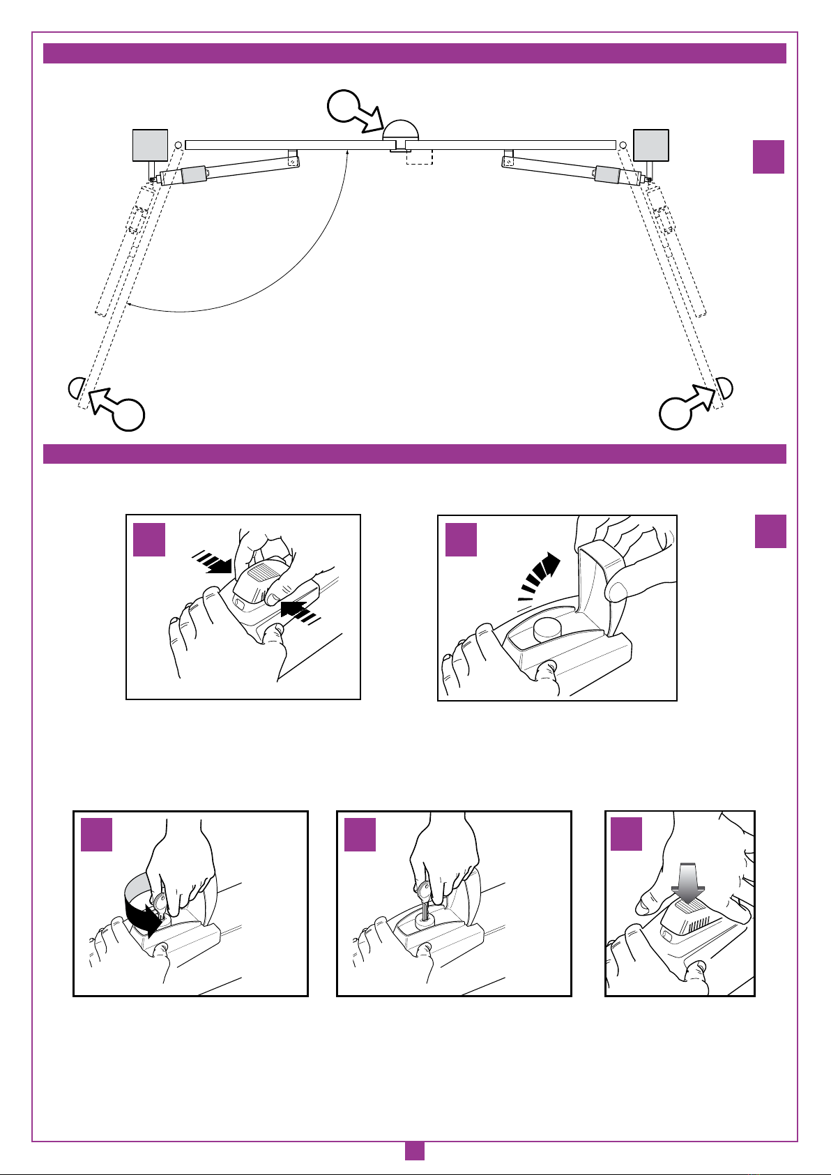
Manual release drawings Pag. 6
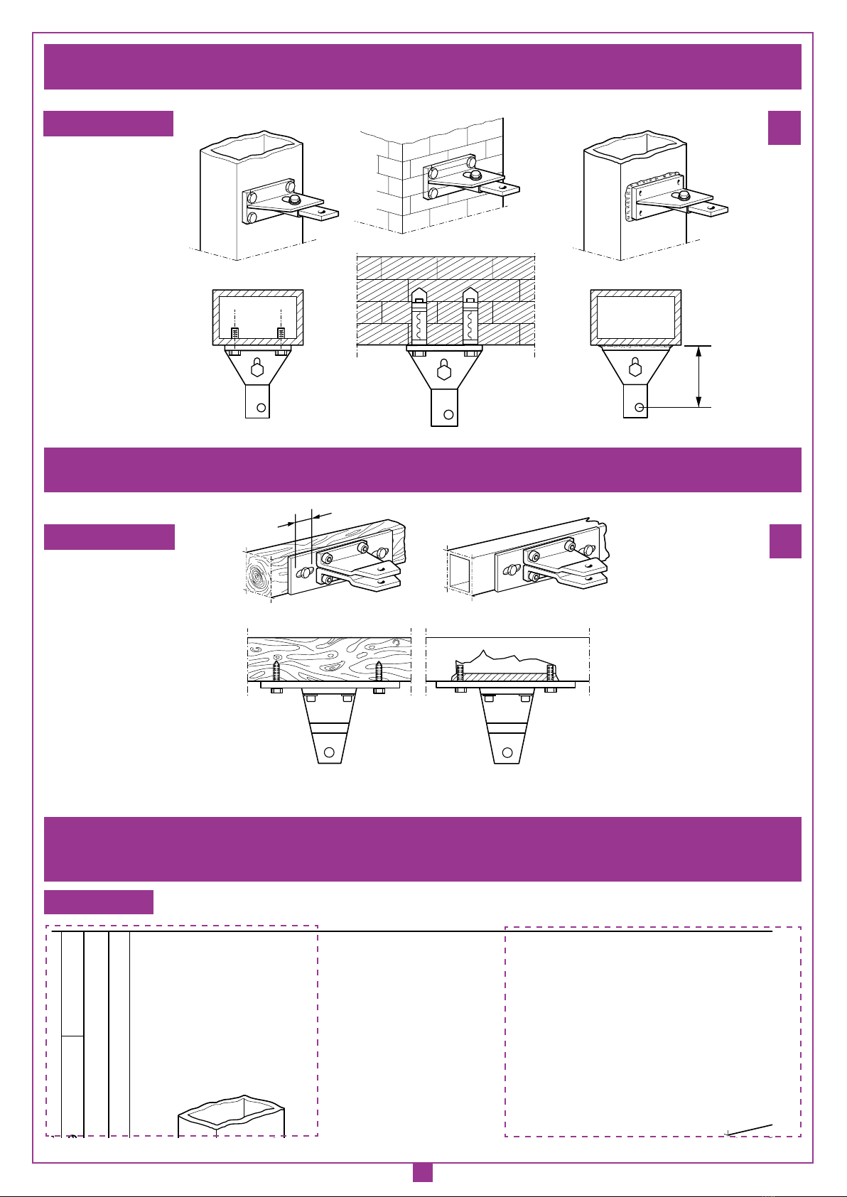
Fitting the holding brackets/electric lock Pag. 7-8
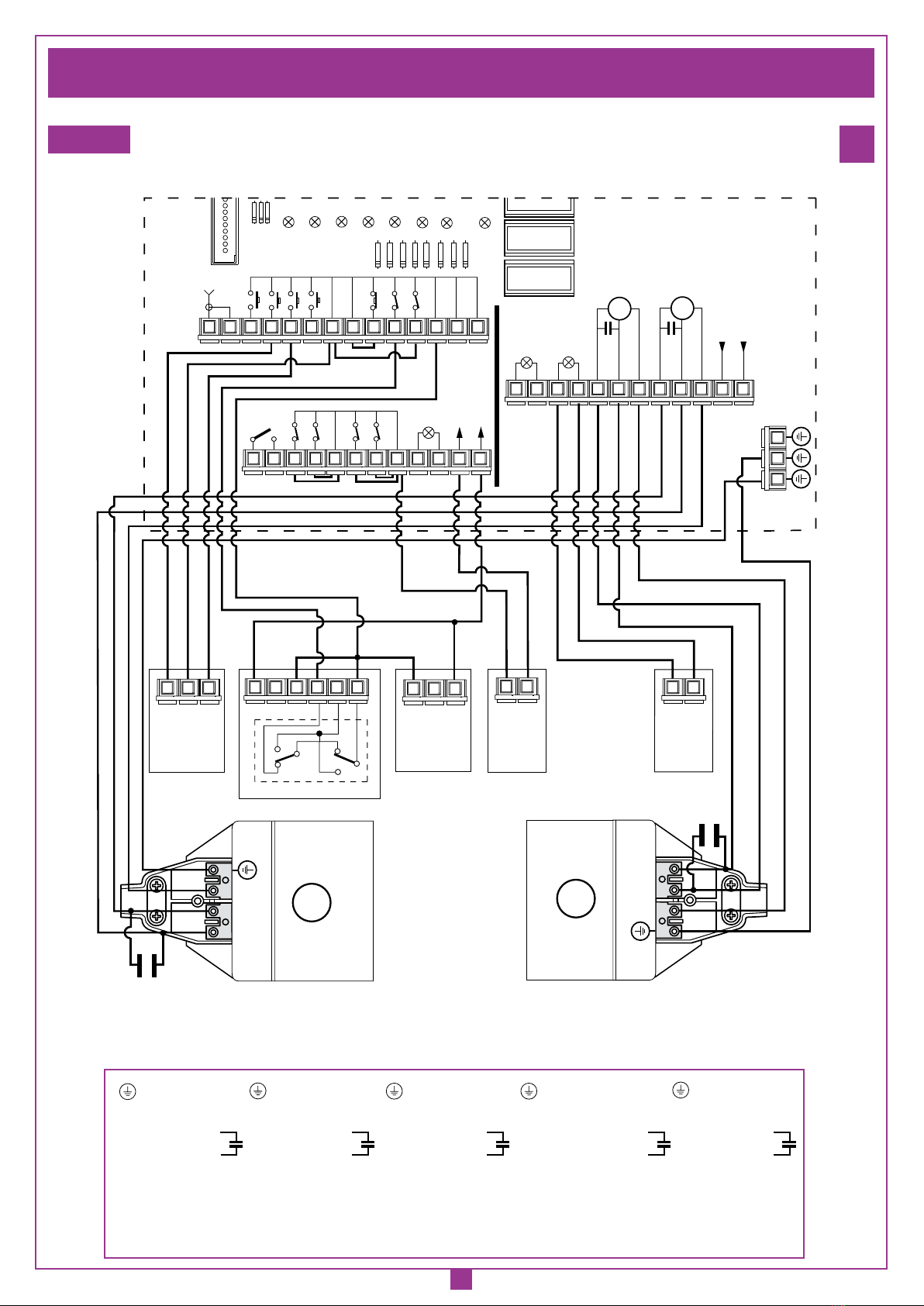
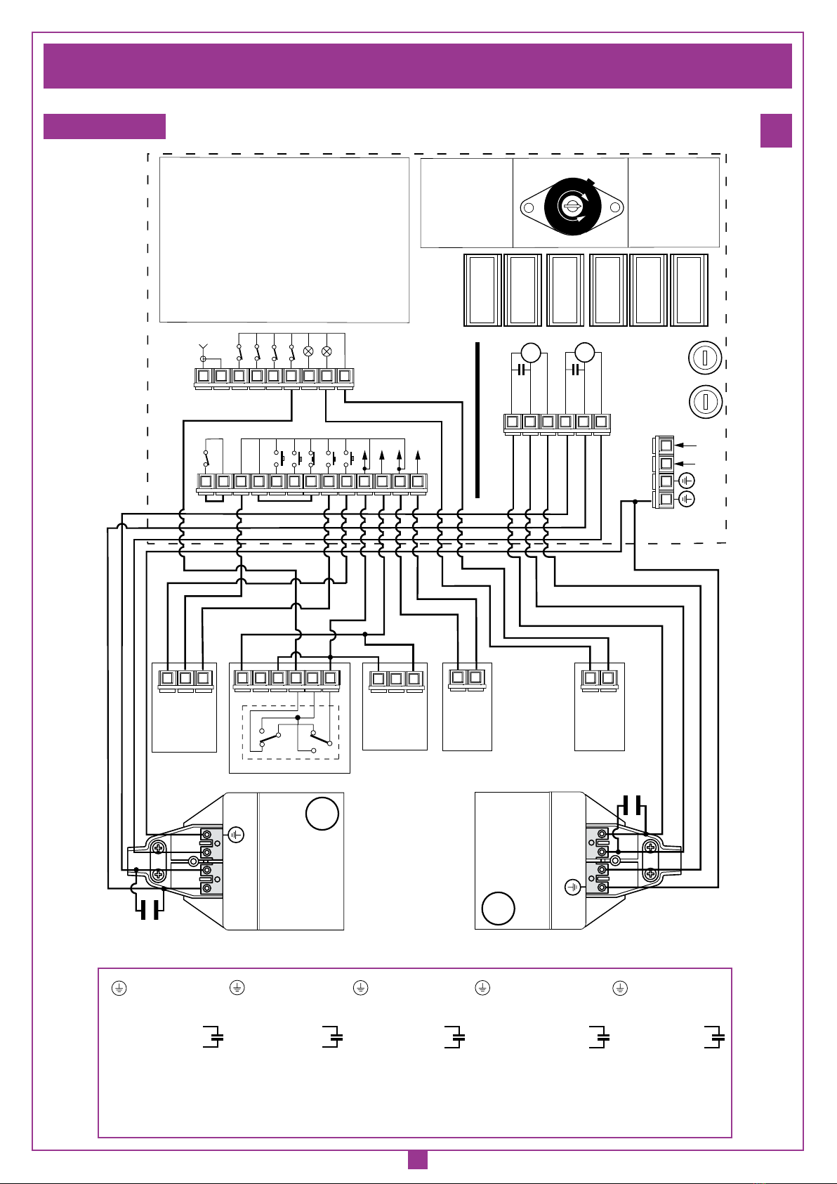
Wiring diagrams (installation examples) Pag. 9-11
Important remarks Pag. 15
User instructions Pag. 15
Installation instructions Pag. 16
Electrical connection Pag. 17
Manual release mechanism Pag. 17
Technical specifications Pag. 28
ATTENTION! Avant de commencer la pose, lire
attentivement les instructions!
Exemple d’installation Pag. 2
Montage Pag. 3-6
Dessins du déverrouillage Pag. 6
Fixation de la patte/serrure électrique Pag. 7-8
Schéma électrique (exemple d’installation) Pag. 9-11
Conseils importants Pag. 18
Domaine d'application Pag. 18
Instructions pour l’installation Pag. 19
Branchement électrique Pag. 20
Déverrouillage manuel Pag. 20
Caractéristiques techniques Pag. 28
ACHTUNG! Bevor mit der Installation begonnen wird,
sollte die Anleitung aufmerksam gelesen werden!
Anlagenart Seite 2
Montagegearbeiten Seite 3-6
Manuelle Entriegelungs Zeichenen Seite 6
Anbringung Halterbügel/Elektroverriegelung Seite 7-8
Elektrischer Schaltplan (Anlagenart) Seite 9-11
Wichtige Hinweise Seite 21
Betriebsanleitung Seite 21
Anleitungen zur Installation Seite 22
Elektrischer anschluss Seite 23
Manuelle Entriegelung Seite 23
Technische Daten Seite 28
AUTOMAZIONE PER CANCELLI A BATTENTE
AUTOMATION FOR HINGED GATES
AUTOMATISME POUR PORTAILS BATTANTS
DREHTORANTRIEBE
AUTOMATIZACION PARA CANCILLAS BATIENTES
ATTENZIONE! Prima di iniziare l'installazione leggere
le istruzioni attentamente!
Esempio d'installazione Pag. 2
Schema di montaggio Pag. 3-6
Disegni di sblocco Pag. 6
Fissaggio staffa/elettroserratura Pag. 7-8
Schema elettrico (impianto tipo) Pag. 9-11
Avvertenze importanti Pag. 12
Istruzioni per l’uso Pag. 12
Istruzione per l’installazione Pag. 13
Collegamento elettrico Pag. 14
Sblocco manuale Pag. 14
Caratteristiche tecniche Pag. 28
¡ATENCIÓN! Antes de iniciar la instalación del sistema,
leer atentamente las instrucciones.
Instalación estándar Pag. 2
Esquema de montaje Pag. 3-6
Dibujos del dispositivo de desbloqueo Pag. 6
Fijación del soporte/electrocerradura Pag. 7-8
Esquema eléctrico (instalación estándar) Pag. 9-11
Advertencias importantes Pag. 24
Instrucciones para el uso Pag. 24
Instrucciones para la instalación Pag. 25
Conexión eléctrica Pag. 26
Desbloqueo manual Pag. 26
Características técnicas Pag. 28
CARDIN ELETTRONICA spa
Via Raffaello, 36
31020 San Vendemiano (TV) Italy
Tel: +39/0438.404011-401818
Fax: +39/0438.401831
email (Europe): Sales.office@cardin.it
Http: www.cardin.it
ZVL240.06-Mod:30/10/2006
ITALIANO
ENGLISH ESPAÑOL
DEUTSCH
FRANÇAIS
Instruction manual Model
ZVL240.06
Series Date
20-07-2005
Questo prodotto è stato testato e collaudato nei laboratori della casa costruttrice, la quale ne ha verificato la
perfetta corrispondenza delle caratteristiche con quelle richieste dalla normativa vigente.
This product has been tried and tested in the manufacturer's laboratory who have verified that the product
conforms in every aspect to the safety standards in force.
Ce produit a été testé et essayé dans les laboratoires du fabriquant. Pour l'installer suivre attentivement
les instructions fournies.
Dieses Produkt wurde in den Werkstätten der Herstellerfirma auf die perfekte Übereinstimmung ihrer
Eigenschaften mit den von den geltenden Normen vorgeschriebenen getestet und geprüft.
Este producto ha sido probado y ensayado en los laboratorios del fabricante, que ha comprobado la perfecta
correspondencia de sus características con las contempladas por la normativa vigente.
BL
Automation
230Vac
Motors
230Vac
Motors 200/BL202
200/BL202L
200/BL202C
200/BL352
200/BL452

2
prodotti Technocity (lamp. fotocellule ecc.)
BL203
13-09-2006
DI0450 Description :
Product Code :
Date :
Drawing number :
P.J.Heath
CARDIN ELETTRONICA S.p.A - 31020 San Vendemiano (TV) Italy - via Raffaello, 36 Tel: 0438/401818 Fax: 0438/401831
Draft :
All rights reserved. Unauthorised copying or use of the information contained in this document is punishable by law
INSTALLAZIONE TIPO BL203
1
4
58
11
10
76
9
230V-50Hz
2
13
3
12
ESEMPIO D'INSTALLAZIONE - INSTALLATION EXAMPLE - EXEMPLE D'INSTALLATION - ANLAGENART - INSTALACIÓN ESTÁNDAR
1
LEGENDA
1 Motoriduttore (SX)
2 Motoriduttore (DX)
3 Fotocellula interna
4 Fotocellula esterna
5 Lampeggiatore
6 Selettore a chiave
7 Elettroserratura
8 Antenna esterna (Cavo coassiale RG58 Impedenza 50Ω)
9 Interruttore onnipolare con apertura contatti min. 3 mm
10 Cavo alimentazione principale
230 Vac
11 Canalatura per collegamenti motori
24 Vdc
12 Canalatura per collegamenti a bassa tensione
13 Programmatore elettronico
Attenzione: Lo schema rappresentato è puramente indicativo e
vienefornitocome base dilavoroalfine di consentireunascelta dei
componentielettroniciCardin da utilizzare.Dettoschemanon costi-
tuisce pertanto vincolo alcuno per l'esecuzione dell'impianto
LEGEND
1 Geared motor (SX - left)
2 Geared motor (DX - right)
3 Internal photocells
4 External photocells
5 Warning lights
6 Mechanical selector switch
7 Electric locking device
8 External antenna (RG58 coaxial cable - impedance 50Ω)
9 All-pole circuit breaker with a minimum of 3 mm between the
contacts
10 Mains cable
230 Vac
11 Channelling for the motor connection cable
24 Vdc
12 Channelling route for low voltage wires
13 Electronic programmer
Attention:The drawing is purelyindicativeandis supplied as work-
ing base from which to choose the Cardin electronic components
makingupthe installation. This drawing thereforedoesnot lay down
any obligations regarding the execution of the installation.
NOMENCLATURE
1 Motoréducteur (SX - gauche)
2 Motoréducteur (SX - droit)
3 Cellule photoélectrique intérieure
4 Cellule photoélectrique extérieure
5 Clignoteur
6 Sélecteur à clé
7 Serrure électrique
8 Antenne (Câble coaxial RG58 - Impédance 50Ω)
9 Interrupteur omnipolaire avec ouverture des contacts d'au
moins 3 mm.
10 Câble d’alimentation principale
230 Vac
11 Chemin de câble branchement moteurs
24 Vdc
12 Chemin pour branchement basse tension
13 Armoire électronique
Attention: le schéma, diffusé à titre purement indicatif, est destiné
à vous aider dans le choix des composants électroniques Cardin
à utiliser. Par conséquent, il n'a aucune valeur obligatoire quant
à la réalisation de l'installation.
ZEICHENERKLÄRUNG
1 Getriebemotor (SX - links)
2 Getriebemotor (DX - rechts)
3 Interne Lichtschranke
4 Externe Lichtschranke
5 Blinklicht
6 Schlüsselschalter
7 Elektroverriegelung
8 Antenne (Koaxialkabel RG58 Impedanz 50Ω)
9 Allpoliger Schalter mit Kontaktenabstand von mindestens 3 mm
10 Hauptversorgungskabel
230 Vac
11 Kanalverlauf für motorverbindungskabel
24 Vdc
12 Kanalverlauf für Anschluss auf Niederspannung
13 Elektronische Steuereinheit
Achtung: Bei dem dargestellten Plan handelt es sich nur um ungefähre
Angaben und er wird als Arbeitsgrundlage geliefert, um eine Auswahl der
zu benutzenden elektronischen Komponenten von Cardin zu erlauben. Der
besagte Plan ist daher für die Ausführung der Anlage nicht bindend.
LEYENDA
1 Motorreductor (SX - izquierda)
2 Motorreductor (SX - derecha)
3 Fotocélula interior
4 Fotocélula exterior
5 Relampagueador
6 Selector con llave
7 Electrocerradura
8 Antena exterior (Cable coaxial RG58 Impedancia 50Ω)
9 Interruptor omnipolar con apertura entre los contactos de 3 mm.
como mínimo.
10 Cable de alimentación principal
230 Vac
11 Canaleta para el cable del motor
24 Vdc
12 Canaleta para el conexionado a baja tensión
13 Centralita electrónica
Atención: La pantalla que se muestra es sólo indicativa y se suministra
como base de trabajo, con el fin de permitir una elección de los compo-
nentes electrónicos Cardin por utilizar; en consecuencia, dicho esquema
no constituye vínculo alguno para la ejecución del sistema.

3
SCALA: 1:2
Prodotti Technocity (sblocco nuovo)
BL202/L
07-07-2003
DI0290 Description :
Product Code :
Date:
Drawing number :
P.J.Heath
CARDIN ELETTRONICA S.p.A - 31020 San Vendemiano (TV) Italy - via Raffaello, 36 Tel: 0438/401818 Fax: 0438/401831
Draft :
All rights reserved. Unauthorised copying or use of the information contained in this document is punishable by law
SCHEMA DI MONTAGGIO BL202/L
12
3
4
5
7
8
6
9
10
2
Nota - Note - Hinweis - Remarque - Nota
SCALA: 1:2
Prodotti Technocity (Sblocco nuovo)
BL202C
07-07-2003
DI0291 Description :
Product Code :
Date :
Drawing number :
P.J.Heath
CARDIN ELETTRONICA S.p.A - 31020 San Vendemiano (TV) Italy - via Raffaello, 36 Tel: 0438/401818 Fax: 0438/401831
Draft :
All rights reserved. Unauthorised copying or use of the information contained in this document is punishable by law
SCHEMA DI MONTAGGIO BL202C
1
2
5
6
9
3
7
10
8
12
4
11
SCHEMA DI MONTAGGIO
ASSEMBLY
MONTAGE
MONTAGEGEARBEITEN
ESQUEMA DE MONTAJE
200/BL202 - 200/BL202L - 200/BL352 - 200/BL452
200/BL352 e 200/BL452 sono privi di sblocco "9"
200/BL352 and 200/BL452 do not feature manual release "9"
200/BL352 et 200/BL452 sont dépourvus de dispositif de déverrouillage "9"
200/BL352 und 200/BL452 besitzen keine Entriegelung «9"
200/BL352 y 200/BL452 están desprovistos de dispositivo de desbloqueo "9"
2
SCHEMA DI MONTAGGIO
ASSEMBLY
MONTAGE
MONTAGEGEARBEITEN
ESQUEMA DE MONTAJE
200/BL202C
3

4
SCALA: 1:2
Prodotti Technocity
BL203C-BL2124C
01-10-2003
DI0315 Description :
Product Code :
Date :
Drawing number :
P.J.Heath
CARDIN ELETTRONICA S.p.A - 31020 San Vendemiano (TV) Italy - via Raffaello, 36 Tel: 0438/401818 Fax: 0438/401831
Draft :
All rights reserved. Unauthorised copying or use of the information contained in this document is punishable by law
Vista pistone
832
390
75
12
120
80
745
80
90
C
SCALA: 1:2
Prodotti Technocity
BL203-BL2124
01-10-2003
DI0313 Description :
Product Code :
Date :
Drawing number :
P.J.Heath
CARDIN ELETTRONICA S.p.A - 31020 San Vendemiano (TV) Italy - via Raffaello, 36 Tel: 0438/401818 Fax: 0438/401831
Draft :
All rights reserved. Unauthorised copying or use of the information contained in this document is punishable by law
Vista pistone
1076
80
120
725
1005
80
12 59 90
A
SCALA: 1:2
Prodotti Technocity
BL203L -BL2124L
01-10-2003
DI0314 Description :
Product Code :
Date :
Drawing number :
P.J.Heath
CARDIN ELETTRONICA S.p.A - 31020 San Vendemiano (TV) Italy - via Raffaello, 36 Tel: 0438/401818 Fax: 0438/401831
Draft :
All rights reserved. Unauthorised copying or use of the information contained in this document is punishable by law
Vista pistone
1416
80
120
900
1350
80
12 54 90
B
DIMENSIONI D'INGOMBRO - EXTERNAL DIMENSIONS - DIMENSIONS D'ENCOMBREMENT - AUSSENABMESSUNGEN - DIMENSIONES MAXIMAS
SCALA: 1:2
Prodotti Technocity
BL352
16-11-98
DI0101 Description :
Product Code :
Date :
Drawing number :
P.J.Heath
CARDIN ELETTRONICA S.p.A - 31020 San Vendemiano (TV) Italy - via Raffaello, 36 Tel: 0438/401818 Fax: 0438/401831
Draft :
All rights reserved. Unauthorised copying or use of the information contained in this document is punishable by law
Vista pistone 352
1096
80
745
1025
80
12 59 90
A
CORSA UTILE "A" = 280 mm
TRAVEL DISTANCE "A" = 280 mm
COURSE UTILE "A" = 280 mm
ARBEITSHUB "A" = 280 mm
CARRERA UTIL "A" = 280 mm
200/BL202
4
200/BL352 - 200/BL452
5
200/BL202L
6
200/BL202C
7
CORSA UTILE "A" = 280 mm
TRAVEL DISTANCE "A" = 280 mm
COURSE UTILE "A" = 280 mm
ARBEITSHUB "A" = 280 mm
CARRERA UTIL "A" = 280 mm
CORSA UTILE "A" = 445 mm
TRAVEL DISTANCE "A" = 445 mm
COURSE UTILE "A" = 445 mm
ARBEITSHUB "A" = 445 mm
CARRERA UTIL "A" = 445 mm
CORSA UTILE "A" = 350 mm
TRAVEL DISTANCE "A" = 350 mm
COURSE UTILE "A" = 350 mm
ARBEITSHUB "A" = 350 mm
CARRERA UTIL "A" = 350 mm

5
SCALA: 1:2
Prodotti Technocity
BL202C
01-02-99
DI0123 Description :
Product Code :
Date :
Drawing number :
P.J.Heath
CARDIN ELETTRONICA S.p.A - 31020 San Vendemiano (TV) Italy - via Raffaello, 36 Tel: 0438/401818 Fax: 0438/401831
Draft :
All rights reserved. Unauthorised copying or use of the information contained in this document is punishable by law
limite d'impiego
α
743 max.
D
X
2
A
C
1
B
389 min
A B C D+X α=0° α=90° α=110° α max
F(Kg) M(Kgm) F(Kg) M(Kgm) F(Kg) M(Kgm)
130 160 0…80 90 43.2 25.6 59.6 35.3 35.8 24.8 110°
130 170 0…80 90 43.8 25.5 65 37.9 41.1 24 110°
180 160 0…80 105 58.3 34.9 57.4 33.7 90°
LIMITI D’IMPIEGO - LIMITS OF USE - CONTRAINTES D'UTILISATION - ANWENDUNGSGRENZEN - LIMITES DE EMPLEO
A
SCALA: 1:2
Prodotti Technocity
BL202
21-10-98
DI0121 Description :
Product Code :
Date :
Drawing number :
P.J.Heath
CARDIN ELETTRONICA S.p.A - 31020 San Vendemiano (TV) Italy - via Raffaello, 36 Tel: 0438/401818 Fax: 0438/401831
Draft :
All rights reserved. Unauthorised copying or use of the information contained in this document is punishable by law
limite d'impiego
B
C
D
α
1000 max. (BL203-2024)
A B C D α=0° α=90° α max
F(Kg) M(Kgm) F(Kg) M(Kgm)
130 120 0…80 90 29,3 26 28 24.8 90°
130 130 0…80 90 29.6 25.9 31 27.2 90°
140 120 0…80 90 31.6 27.7 31.1 27.3 90°
140 140 0…80 90 31.9 27.7 34.2 29.7 90°
150 130 0…80 90 33.6 29.5 31.2 27.3 90°
1
2
1020 max. (BL352-452)
750 min (BL352-452)
730 min (BL202-202M)
SCALA: 1:2
Prodotti Technocity
BL202L
29-01-99
DI0122 Description :
Product Code :
Date :
Drawing number :
P.J.Heath
CARDIN ELETTRONICA S.p.A - 31020 San Vendemiano (TV) Italy - via Raffaello, 36 Tel: 0438/401818 Fax: 0438/401831
Draft :
All rights reserved. Unauthorised copying or use of the information contained in this document is punishable by law
limite d'impiego
D
α
1350 max.
X2
A
C
1
B
905 min
A B C D+X α=0° α=90° α=110° α max
F(Kg) M(Kgm) F(Kg) M(Kgm) F(Kg) M(Kgm)
160 150 0…80 90+20 26,5 32 25.9 31.22 13 15.8 110°
160 180 0…80 90+20 27 31.8 32.5 38.3 19.2 22.6 110°
180 180 0…80 90+20 30 35.3 32.7 38.5 17.7 20.8 110°
180 210 0…80 90+20 30,6 35 39.9 45.7 24.4 28 110°
200 180 0…80 90+20 33 38.8 33 38.8 16 19 110°
X= Spessore da aggiungere a cura dell'installatore
X= Spacer to be added by the installer
X= Cale à ajouter par les soins de l'installateur
X= Vom Installateur hinzuzufügendes Distanzstück
X= Distanciador que el instalador debe añadir
X= Spessore da aggiungere a cura dell'installatore
X= Spacer to be added by the installer
X= Cale à ajouter par les soins de l'installateur
X= Vom Installateur hinzuzufügendes Distanzstück
X= Distanciador que el instalador debe añadir
Importante! Per un’installazione ottimale utilizzare i dati evidenziati in grigio.
Important! For an optimised installation use the values highlighted in grey.
Important! Pour optimiser l'installation, appliquer les données mises en évidence dans les cases en gris.
Wichtig! Für eine optimale Installation sind die grau markierten Zahlenwerte zu verwenden.
¡Importante! Para una instalación perfecta utilizar los datos evidenciados en gris.
200/BL202
200/BL352
200/BL452
8
200/BL202L 9
200/BL202C
10

6
SBLOCCO MANUALE - MANUAL RELEASE - DÉVERROUILLAGE MANUEL - MANUELLE ENTRIEGELUNG - DESBLOQUEO MANUAL
ESEMPIO D’INSTALLAZIONE-INSTALLATION EXAMPLE-EXEMPLE D'INSTALLATION-INSTALLATIONSART-EJEMPLO DE INSTALACIÓN
SCALA: 1:
Prodotti Technocity
BL202 (serie)
30-07-98
DI0091 Description :
Product Code :
Date :
Drawing number :
P.J.Heath
CARDIN ELETTRONICA S.p.A - 31020 San Vendemiano (TV) Italy - via Raffaello, 36 Tel: 0438/401818 Fax: 0438/401831
Draft :
All rights reserved. Unauthorised copying or use of the information contained in this document is punishable by law
Installazione tipo
α
2
1
3
11
12
Sblocco motore fig.1
02.07.03
DM0721 Description :
Product Code :
Date :
Drawing number :
P.J.Heath
CARDIN ELETTRONICA S.p.A - 31020 San Vendemiano (TV) Italy - via Raffaello, 36 Tel: 0438/401818 Fax: 0438/401831
Draft :
All rights reserved. Unauthorised copying or use of the information contained in this document is punishable by law
BL202
SBLOCCO BL
Sblocco motore fig.2
02.07.03
DM0722 Description :
Product Code :
Date :
Drawing number :
P.J.Heath
CARDIN ELETTRONICA S.p.A - 31020 San Vendemiano (TV) Italy - via Raffaello, 36 Tel: 0438/401818 Fax: 0438/401831
Draft :
All rights reserved. Unauthorised copying or use of the information contained in this document is punishable by law
BL202
SBLOCCO BL
Sblocco motore fig.3
02.07.03
DM0723 Description :
Product Code :
Date :
Drawing number :
P.J.Heath
CARDIN ELETTRONICA S.p.A - 31020 San Vendemiano (TV) Italy - via Raffaello, 36 Tel: 0438/401818 Fax: 0438/401831
Draft :
All rights reserved. Unauthorised copying or use of the information contained in this document is punishable by law
BL202
SBLOCCO BL
Sblocco motore fig.4
02.07.03
DM0724 Description :
Product Code :
Date :
Drawing number :
P.J.Heath
CARDIN ELETTRONICA S.p.A - 31020 San Vendemiano (TV) Italy - via Raffaello, 36 Tel: 0438/401818 Fax: 0438/401831
Draft :
All rights reserved. Unauthorised copying or use of the information contained in this document is punishable by law
BL202
SBLOCCO BL
A B
DE
Sblocco motore fig.3
02.07.03
DM0726 Description :
Product Code :
Date :
Drawing number :
P.J.Heath
CARDIN ELETTRONICA S.p.A - 31020 San Vendemiano (TV) Italy - via Raffaello, 36 Tel: 0438/401818 Fax: 0438/401831
Draft :
All rights reserved. Unauthorised copying or use of the information contained in this document is punishable by law
BL202
SBLOCCO BL
C

7
SCALA: 1:2
Prodotti Technocity
BL202 (SERIE)
29-07-98
DI0082 Description :
Product Code :
Date :
Drawing number :
P.J.Heath
CARDIN ELETTRONICA S.p.A - 31020 San Vendemiano (TV) Italy - via Raffaello, 36 Tel: 0438/401818 Fax: 0438/401831
Draft :
All rights reserved. Unauthorised copying or use of the information contained in this document is punishable by law
Staffa attacco pilastro
SCALA: 1:2
Prodotti Technocity
BL202 (SERIE)
29-07-98
DI0083 Description :
Product Code :
Date :
Drawing number :
P.J.Heath
CARDIN ELETTRONICA S.p.A - 31020 San Vendemiano (TV) Italy - via Raffaello, 36 Tel: 0438/401818 Fax: 0438/401831
Draft :
All rights reserved. Unauthorised copying or use of the information contained in this document is punishable by law
Staffa attacco cancello BL202/L
SCALA: 1:2
Prodotti Technocity
BL202 (SERIE)
29-07-98
DI0084 Description :
Product Code :
Date :
Drawing number :
P.J.Heath
CARDIN ELETTRONICA S.p.A - 31020 San Vendemiano (TV) Italy - via Raffaello, 36 Tel: 0438/401818 Fax: 0438/401831
Draft :
All rights reserved. Unauthorised copying or use of the information contained in this document is punishable by law
Staffa attacco cancello BL202C
FISSAGGIO STAFFA POSTERIORE (A PILASTRO) - FITTING THE REAR BRACKET (TO A COLUMN) - FIXATION DE LA PATTE POSTÉRIEURE
(AU PILIER) - ANBRINGUNG HALTEBÜGEL HINTEN (AN DER SÄULE) - FIJACIÓN DEL SOPORTE POSTERIOR (EN EL PILAR)
FISSAGGIO STAFFA ANTERIORE (A CANCELLO) - FITTING THE FRONT BRACKET (TO THE GATE) - FIXATION DE LA PATTE ANTÉRIEURE
(AU PORTAIL) - ANBRINGUNG HALTEBÜGEL VORNE (AM TOR) - FIJACIÓN DEL SOPORTE ANTERIOR (EN LA CANCILLA)
FISSAGGIO STAFFA ANTERIORE (A CANCELLO) - FITTING THE FRONT BRACKET (TO THE GATE) - FIXATION DE LA PATTE ANTÉRIEURE
(AU PORTAIL) - ANBRINGUNG HALTEBÜGEL VORNE (AM TOR) - FIJACIÓN DEL SOPORTE ANTERIOR (EN LA CANCILLA)
200/BL202
200/BL202L
200/BL202C
200/BL352
200/BL452
13
200/BL202
200/BL202L
200/BL352
200/BL452
14
200/BL202C
15

8
STAFFA POSTERIORE REGOLABILE (OPZIONALE) - FITTING THE ADJUSTABLE REAR BRACKET (OPTIONAL) - PATTE POSTÉRIEURE
RÉGLABLE (EN OPTION) - HINTERER, EINSTELLBARER HALTEBÜGEL (EXTRA) - SOPORTE POSTERIOR REGULABLE (OPCIONAL)
STAFFA ANTERIORE REGOLABILE (OPZIONALE) - FITTING THE ADJUSTABLE FRONT BRACKET (OPTIONAL) - PATTE ANTÉRIEURE
RÉGLABLE (EN OPTION) - VORNER, EINSTELLBARER HALTEBÜGEL (EXTRA) - SOPORTE ANTERIOR REGULABLE (OPCIONAL)
SCALA: 1:2
Prodotti Technocity
BL202 (SERIE)
07-10-98
DI0095 Description :
Product Code :
Date :
Drawing number :
P.J.Heath
CARDIN ELETTRONICA S.p.A - 31020 San Vendemiano (TV) Italy - via Raffaello, 36 Tel: 0438/401818 Fax: 0438/401831
Draft :
All rights reserved. Unauthorised copying or use of the information contained in this document is punishable by law
Staffa attacco pilastro regolabile
94 min
131 max
SCALA: 1:2
Prodotti Technocity
BL202 (SERIE)
12-10-98
DI0096 Description :
Product Code :
Date :
Drawing number :
P.J.Heath
CARDIN ELETTRONICA S.p.A - 31020 San Vendemiano (TV) Italy - via Raffaello, 36 Tel: 0438/401818 Fax: 0438/401831
Draft :
All rights reserved. Unauthorised copying or use of the information contained in this document is punishable by law
Staffa attacco cancello regolabile
20
206/BL201STAP
16
206/BL201SUAR
17
41 mm
41 mm
Description :
Product Code :
Date :
Drawing number :
P.J.Heath
CARDIN ELETTRONICA S.p.A - 31020 San Vendemiano (TV) Italy - via Raffaello, 36 Tel: 0438/401818 Fax: 0438/401831
Draft :
All rights reserved. Unauthorised copying or use of the information contained in this document is punishable by law
Installazione squadretta posteriore 41 mm
BL
29-10-2006
DI0461
STAFFA POSTERIORE - REAR BRACKET
PATTE POSTÉRIEURE - HINTERER HALTEBÜGEL
SOPORTE POSTERIOR
PREINSTALLAZIONE STAFFA POSTERIORE/ANTERIORE - PRE-INSTALLATION FRONT/REAR BRACKET
PRÉINSTALLATION PATTE POSTÉRIEURE/ANTÉRIEURE - VORMONTAGE HINTERER/VORNER HALTEBÜGEL
PREINSTALACIÓN SOPORTE POSTERIOR/ANTERIOR
STAFFA ANTERIORE - FRONT BRACKET
PATTE ANTÉRIEURE - VORNER HALTEBÜGEL
SOPORTE ANTERIOR
18
200/BL202C

9
SCHEMA ELETTRICO IMPIANTO TIPO - STANDARD WIRING DIAGRAM - SCHÉMA ÉLECTRIQUE DE L'EXEMPLE D'INSTALLATION
ELEKTRISCHER SCHALTPLAN ANLAGENART - ESQUEMA ELECTRICO INSTALACIÓN ESTANDAR
- Terra
N - Comune
2 - Apre
3 - Chiude
- Ground
N - Neutral
2 - Open
3 - Close
- Terre
N - Commun
2 - Ouvre
3 - Ferme
- Erdung
N - Gemeinsam
2 - Öffnen
3 - Schließen
- Tierra
N - Común
2 - Abre
3 - Cierra
Programmatore a microcontrollore per 2 motori
BL
28-03-2004
DI00333 Description :
Product Code :
Date :
Drawing number :
P.J.Heath
CARDIN ELETTRONICA S.p.A - 31020 San Vendemiano (TV) Italy - via Raffaello, 36 Tel: 0438/401818 Fax: 0438/401831
Draft :
All rights reserved. Unauthorised copying or use of the information contained in this document is punishable by law
COLLEGAMENTO SERIE BL203
C
LD1 LD2 LD3 LD4 LD6 LD7
LD5 LD8
TAL
CSER
262524232221201918171615
383736353433323130292827
TA
ANTENNA TC TD
FTC_S
FTC_I
NC NCNC
TB
COMUNE
COMUNE
COMUNE
COMUNE
COMUNE
1
141312111098765432
FCC_1
FCA_1
NC NC
COMUNE
FCC_2
FCA_2
NC NC
COMUNE
NAC
OUT CH2
LS
24V3W
ELS
12V15W
OUT
24V
NA NA NA NA
LC
110-230V~
LP
110-230V~
M2
CHIUSURA
COMUNE
APERTURA
C M1
CHIUSURA
COMUNE
APERTURA
N F
414039
SEL
24V
PONTICELLI
12V 0
C
1
65432
NA
NC NC
C
NA
FTC-RX
1
32
CLOSING
COMMON
OPENING
1
32
24V
12V
0
FTC-TX
N 2 3
M1
N 2 3
M2
PONTICELLI
1
2
C1
1
2
ELS LP
230V (EU)
C2
UTILIZZARE PER IL COLLEGAMENTO ELETTRICO CAVO MULTIPOLARE FLESSIBILE 3 x 1 + T
USE FLEXIBLE MULTIWIRE CABLES FOR THE ELECTRICAL CONNECTION 3 x 1 + EARTH WIRE
POUR LE BRANCHEMENT ÉLECTRIQUE, UTILISER UN CÂBLE MULTIPOLAIRE FLEXIBLE 3 X 1 + T
ZUM ANSCHLUSS EIN MEHRPOLIGES FLEXIBLES ELEKTROKABEL 3 X 1 + T VERWENDEN.
PARA LA CONEXIÓN ELECTRICA UTILIZAR UN CABLE MULTIPOLAR FLEXIBLE 3 x 1 + T
PRG811
19

10
11 12
C
TAL
Programmatore (PRG101LSOCE) per 1-2 motori
Serie BL203
04-03-2004
DI0134 Description :
Product Code :
Date :
Drawing number :
P.J.Heath
CARDIN ELETTRONICA S.p.A - 31020 San Vendemiano (TV) Italy - via Raffaello, 36 Tel: 0438/401818 Fax: 0438/401831
Draft :
All rights reserved. Unauthorised copying or use of the information contained in this document is punishable by law
COLLEGAMENTO SERIE BL230
(110V - 230V)
2322212019181716151413
1098765
TD
ANTENNA
TC TA
NC
TB
COMMON
FCA
FCC
COMMON
NO NO NO NO
M2
CLOSING
COMMON
OPENING
C M1
OPENING
COMMON
CLOSING
432
24V 12V 0
C
1
65432
NO
NC NC
C
NO
1
32
CLOSING
COMMON
OPENING
1
32
24V
12V
0
N 2 3
M1
N 2 3
M2
BRIDGE
1
2
C2
1
2
CLOSING M2
OPENING M2
CLOSING M1
OPENING M1
COMMON
TORQUE LIMIT
Max: 230 Vac
A: 195 Vac
B: 170 Vac
C: 145 Vac
MIN: 120 Vac
M
A
X
A
B
C
M
I
N
COMMON
24V AC
ELS
12V ~
24 25 26 27 28 29 30 31 32
NC NC
FTC_S
NC
FTC_I
NC
LS LP
24V
Neutral
Live
LEGEND
TA: OPENING BUTTON
TC: CLOSING BUTTON
TB: BLOCKING BUTTON (bridge if unused)
TD: DYNAMIC BUTTON (open-close)
TAL: LIMITED OPENING
FCC: CLOSING TRAVEL LIMIT (bridge if unused)
FCA: OPENING TRAVEL LIMIT (bridge if unused)
FTC_S: STOP PHOTOCELL (bridge if unused)
FTC_I: INVERTING PHOTOCELL(bridge if unused)
BSP: PASSIVE SAFETY INPUT (bridge if unused)
LP: FLASHING WARNING LIGHTS (24Vac)
LS: INDICATOR LAMP (24Vac)
ELS: ELECTRIC LOCKING DEVICE (12Vac)
NO: NORMALLY OPEN CONTACT
NC: NORMALLY CLOSED CONTACT
C
NO
NC
1
BRIDGE
BSP
NC
FUSE
5A (230V)
10A (110V)
C1
TORQUE LIMITER
Max: 110 Vac
A: 100 Vac
B: 90 Vac
C: 80 Vac
MIN: 70 Vac
230V 50Hz 110V 60Hz
FUSE
5A (230V)
10A (110V)
230V (EEC)
110V (USA)
EUROPE USA
SEL
FTC-RX
FTC-TX ELS LP
- Terra
N - Comune
2 - Apre
3 - Chiude
- Ground
N - Neutral
2 - Open
3 - Close
- Terre
N - Commun
2 - Ouvre
3 - Ferme
- Erdung
N - Gemeinsam
2 - Öffnen
3 - Schließen
- Tierra
N - Común
2 - Abre
3 - Cierra
UTILIZZARE PER IL COLLEGAMENTO ELETTRICO CAVO MULTIPOLARE FLESSIBILE 3 x 1 + T
USE FLEXIBLE MULTIWIRE CABLES FOR THE ELECTRICAL CONNECTION 3 x 1 + EARTH WIRE
POUR LE BRANCHEMENT ÉLECTRIQUE, UTILISER UN CÂBLE MULTIPOLAIRE FLEXIBLE 3 X 1 + T
ZUM ANSCHLUSS EIN MEHRPOLIGES FLEXIBLES ELEKTROKABEL 3 X 1 + T VERWENDEN.
PARA LA CONEXIÓN ELECTRICA UTILIZAR UN CABLE MULTIPOLAR FLEXIBLE 3 x 1 + T
SCHEMA ELETTRICO IMPIANTO TIPO - STANDARD WIRING DIAGRAM - SCHÉMA ÉLECTRIQUE DE L'EXEMPLE D'INSTALLATION
ELEKTRISCHER SCHALTPLAN ANLAGENART - ESQUEMA ELECTRICO INSTALACIÓN ESTANDAR
PRG101LSOCE
20

11
- Terra
N - Comune
2 - Apre
3 - Chiude
- Ground
N - Neutral
2 - Open
3 - Close
- Terre
N - Commun
2 - Ouvre
3 - Ferme
- Erdung
N - Gemeinsam
2 - Öffnen
3 - Schließen
- Tierra
N - Común
2 - Abre
3 - Cierra
C
TAL
Programmatore (PRG101LSO) senza BSP
Serie BL203
05-03-2004
DI0335 Description :
Product Code :
Date :
Drawing number :
P.J.Heath
CARDIN ELETTRONICA S.p.A - 31020 San Vendemiano (TV) Italy - via Raffaello, 36 Tel: 0438/401818 Fax: 0438/401831
Draft :
All rights reserved. Unauthorised copying or use of the information contained in this document is punishable by law
COLLEGAMENTO SERIE BL203
(110V - 230V)
2120
19
1817161514131211
56789
10
TD
ANTENNA
TC TA
NC
TB
COMMON
FCA
FCC
COMMON
NO NO NO NO
M2
CLOSING
COMMON
OPENING
C M1
OPENING
COMMON
CLOSING
12
24V 12V 0
C
1
65432
NO
NC NC
C
NO
1
32
CLOSING
COMMON
OPENING
1
32
24V
12V
0
N 2 3
M1
N 2 3
M2
BRIDGE
1
2
C2
1
2
CLOSING M2
OPENING M2
CLOSING M1
OPENING M1
COMMON
TORQUE LIMIT
Max: 230 Vac
A: 195 Vac
B: 170 Vac
C: 145 Vac
MIN: 120 Vac
M
A
X
A
B
C
M
I
N
COMMON
24V AC
ELS12V ~
22 23 24 25 26 27 28 29 30
NC NC
FTC_S
NC
FTC_I
NC
LS LP
24V
N.
Live
LEGEND
TA: OPENING BUTTON
TC: CLOSING BUTTON
TB: BLOCKING BUTTON (bridge if unused)
TD: DYNAMIC BUTTON (open-close)
TAL: LIMITED OPENING
FCC: CLOSING TRAVEL LIMIT (bridge if unused)
FCA: OPENING TRAVEL LIMIT (bridge if unused)
FTC_S: STOP PHOTOCELL (bridge if unused)
FTC_I: INVERTING PHOTOCELL(bridge if unused)
LP: FLASHING WARNING LIGHTS (24Vac)
LS: INDICATOR LAMP (24Vac)
ELS: ELECTRIC LOCKING DEVICE (12Vac)
NO: NORMALLY OPEN CONTACT
NC: NORMALLY CLOSED CONTACT
C
NO
NC
3
FUSE
5A (230V)
10A (110V)
C1
TORQUE LIMITER
Max: 110 Vac
A: 100 Vac
B: 90 Vac
C: 80 Vac
MIN: 70 Vac
230V 50Hz 110V 60Hz
230V (EEC)
110V (USA)
EUROPE USA
4
SEL
FTC RX
FTC TX ELS LP
UTILIZZARE PER IL COLLEGAMENTO ELETTRICO CAVO MULTIPOLARE FLESSIBILE 3 x 1 + T
USE FLEXIBLE MULTIWIRE CABLES FOR THE ELECTRICAL CONNECTION 3 x 1 + EARTH WIRE
POUR LE BRANCHEMENT ÉLECTRIQUE, UTILISER UN CÂBLE MULTIPOLAIRE FLEXIBLE 3 X 1 + T
ZUM ANSCHLUSS EIN MEHRPOLIGES FLEXIBLES ELEKTROKABEL 3 X 1 + T VERWENDEN.
PARA LA CONEXIÓN ELECTRICA UTILIZAR UN CABLE MULTIPOLAR FLEXIBLE 3 x 1 + T
SCHEMA ELETTRICO IMPIANTO TIPO - STANDARD WIRING DIAGRAM - SCHÉMA ÉLECTRIQUE DE L'EXEMPLE D'INSTALLATION
ELEKTRISCHER SCHALTPLAN ANLAGENART - ESQUEMA ELECTRICO INSTALACIÓN ESTANDAR
PRG101LSO
21

12
• Ilpresentemanualesirivolgeapersoneabilitateall'installazionedi
"APPARECCHIUTILIZZATORIDIENERGIAELETTRICA"erichiede
unabuonaconoscenzadellatecnica, esercitatainformaprofessionale
e della normativa vigente. I materiali usati devono essere certificati
e risultare idonei alle condizioni ambientali di installazione.
• Leoperazionidimanutenzionedevonoessereeseguitedapersonale
qualificato. Prima di eseguire qualsiasi operazione di pulizia o di
manutenzione,disinserirel'apparecchiaturadallaretedialimentazione
elettrica.
• Le apparecchiature qui descritte dovranno essere destinate solo
all'uso per il quale sono state espressamente concepite:
"La motorizzazione di cancelli a battente ad una o due ante".
Il dispositivo è adatto alla movimentazione di cancelli a battente,
ad una o due ante.
• L'applicazioneèpossibilesiaasx che a dx della luce passaggio.
• Questoprodottoèstatoprogettatoefabbricatointuttelesueparti
a cura della Cardin Elettronica la quale ne ha verificato la perfetta
corrispondenza delle caratteristiche con quelle richieste dalla nor-
mativa vigente.
L'utilizzo dei prodotti e la loro destinazione ad usi diversi da quelli
previsti e/o consigliati, non è stata sperimentata dal costruttore,
pertanto i lavori eseguiti sono sotto la completa responsabilità del-
l'installatore.
Il costruttore non risponde qualora l'impianto elettrico non risulti
conforme alle norme vigenti ed in particolare qualora il circuito di
protezione (terra) non sia efficiente.
È responsabilità dell’installatore verificare le seguenti condizioni di
sicurezza:
1) L’installazione deve essere sufficientemente lontana dalla strada in
modo da non costituire pericolo per la circolazione.
2) L’operatore deve essere installato all’interno della proprietà ed il
cancello non deve aprirsi verso l’area pubblica.
3) Il cancello motorizzato è principalmente adibito al passaggio di
vetture. Dove possibile installare per pedoni un ingresso separato.
4) Icomandidevono essereposti in vista,manonentroilraggio d’azione
del cancello. Inoltre quelli installati all’esterno devono essere protetti
da una sicurezza tale da prevenire l’uso non autorizzato.
5) È buona norma segnalare l’automazione con targhe di avvertenza
(similia quellain figura)che devonoesserefacilmente visibili.Qualora
l’automazionesiaadibita al solopassaggiodiveicoli dovrannoessere
poste due targhe di avvertenza di divieto di transito pedonale (una
all’interno, una all’esterno).
6) Rendere consapevole l’utente che bambini o animali domestici non
devono giocare o sostare nei pressi del cancello. Se necessario
indicarlo in targa.
7) Qualora l’anta completamente aperta vada ad avvicinarsi ad una
struttura fissa lasciando uno spazio di almeno 500 mm, tale spazio
deve essere protetto con una costa sensibile
antischiacciamento.
8) La bontà della connessione di terra dell’appa-
recchiaturaè fondamentaleai finidella sicurezza
elettrica.
9) Per qualsiasi dubbio a riguardo della sicurezza
dell’installazione, non procedere ma rivolgersi
al distributore del prodotto.
DESCRIZIONE TECNICA
200/BL202 Attuatore elettromeccanico autobloccante per ante
fino a 2 m, 150 kg di peso per anta.
200/BL202L Attuatore elettromeccanico autobloccante per ante
fino a 2 m, 150 kg di peso per anta. Se utilizzato con la max corsa
per aperture a 90° può essere utilizzato per ante fino a 4 m, 150
kg per anta con l'aggiunta di una elettroserratura per garantire il
blocco dell'anta in chiusura.
200/BL202C Attuatore elettromeccanico autobloccante per ante
fino a 1,8 m, 150 kg di peso per anta. Se utilizzato con la max
corsa per aperture a 90° può essere utilizzato per ante fino a 3 m,
150 kg per anta con l'aggiunta di una elettroserratura per garantire
il blocco dell'anta in chiusura.
200/BL352 Attuatore elettromeccanico reversibile per ante fino a
3,5 m, 300 kg di peso per anta.
200/BL452 Attuatore elettromeccanico reversibile per ante fino a
4,5 m, 300 kg di peso per anta.
- Motore monofase montato su calotte in alluminio pressofuso
con protezione termica incorporata.
- Carter di copertura in alluminio estruso.
- Particolari sblocco in plastica antiurto.
- Riduttore con ingranaggi in acciaio racchiusi in semigusci di
alluminio pressofuso (BL202-202L-202C).
- Riduttore epicicloidale ad alta silenziosità e vite senza fine in
acciaio con ricircolo di sfera (BL352-452).
- Staffe e particolari d'aggancio in acciaio zincato.
- Lubrificazione a grasso fluido permanente.
ACCESSORI
206/BL201STAP - Staffa posteriore a muro regolabile.
206/BL201SUAR - Piatto anteriore regolabile per staffa
attacco cancello.
980/XLSE11C - Elettroserrattura 12 Vac.
I comandi minimi che possono essere installati sono APERTURA-
STOP-CHIUSURA, tali comandi devono essere posti in un luogo
non accessibile a bambini o minori e fuori dal raggio d’azione del
cancello. Prima di procedere all'esecuzione dell'impianto verificare
che la struttura da automatizzare sia in perfetta efficienza nelle
sue parti fisse e mobili e realizzata in conformità alla normativa
vigente.
A tal fine accertarsi della sufficiente rigidità del telo cancello (se
necessario intervenire con rinforzi sulla struttura) e del buon fun-
zionamento dei perni (si consiglia comunque di lubrificare tutte
le parti in movimento usando lubrificanti che mantengano uguali
caratteristiche di attrito nel tempo e adatti a funzionare tra -20 e
+70°C).
• Controllareifranchidisicurezzatrapartisseepartimobili:
- lasciare uno spazio di 30 mm minimo tra il cancello ed il pilastro
di supporto per tutta l’altezza e per tutto l’arco di apertura del
cancello;
- assicurarsi che lo spazio tra il cancello ed il pavimento non
superi mai 30 mm per tutto l’arco di apertura del cancello.
• Lasupercie delle ante non devepresentareaperturetali da
permettere il passaggio della mano o del piede di persone.
• Controllarel'esattoposizionamentodiperniecerniere,illoro
buono stato di mantenimento e lubrificazione (è importante
che la cerniera superiore e quella inferiore siano a piombo tra
loro).
CONSIDERAZIONI GENERALI DI SICUREZZA
AVVERTENZE IMPORTANTI AVVERTENZE IMPORTANTI AVVERTENZE IMPORTANTI
PERRIDURREILRISCHIODIFERITEGRAVIOMORTE,LEGGEREATTENTAMENTELESEGUENTI
AVVERTENZEPRIMA DIPROCEDERE ALL’INSTALLAZIONE. PRESTARE PARTICOLAREATTEN-
ZIONE A TUTTE LE SEGNALAZIONI DISPOSTE NEL TESTO. IL MANCATO RISPETTO DI
QUESTE POTREBBE COMPROMETTERE IL BUON FUNZIONAMENTO DEL SISTEMA.
APERTURA AUTOMATICA
NON AVVICINARSI
NON PERMETTERE A BAMBINI O AD
ANIMALI DOMESTICI DI SOSTARE NEL
RAGGIO D'AZIONE DEL CANCELLO
ATTENZIONE
ISTRUZIONI PER L'INSTALLAZIONE

13
SCALA: 1:2
Prodotti Technocity
BL352
16-11-98
DI0103 Description :
Product Code :
Date :
Drawing number :
P.J.Heath
CARDIN ELETTRONICA S.p.A - 31020 San Vendemiano (TV) Italy - via Raffaello, 36 Tel: 0438/401818 Fax: 0438/401831
Draft :
All rights reserved. Unauthorised copying or use of the information contained in this document is punishable by law
S c a r i c o c o n d e n s a B L 3 5 2 / 4 5 2
A
ATTENZIONE! Installare sempre le battute di arresto mec-
canico dell’anta (pos 1,2,3 fig. 11).
• Prevedereilpercorsodeicavisecondolenecessitàdiapplica-
zione dei dispositivi di comando e sicurezza (ved. impianto tipo
fig. 1 pag. 2).
• Controllare che l’operatore sia proporzionato alle dimensioni
del cancello e alla frequenza d’uso (intermittenza di lavoro, pag.
28).
FISSAGGIO DEL DISPOSITIVO 200/BL202- BL202L
Il dispositivo può essere fissato sia alla sinistra che alla destra
luce passaggio.
Una corretta installazione deve rispettare la procedura indicata.
• Portarel'anta/einposizionedichiuso.
• Scegliereiltipodiinstallazione(g.8,9pag.5).
• Fissareapilastro(g.13pag.7)lastaffadicoda,rispettandole
quote "A" e "B", dopo aver verificato la posizione della cerniera
cancello rispetto al pilastro (quota "C" fig. 8, 9 pag. 5) e in base
al tipo di apertura d'anta da effettuare.
• Fissareconl'appositoperno"1" l'attuatore alla staffa di coda
"5" (fig. 2 pag. 3) e col perno "7" alla staffa di testa "6".
• Portarelostelo dell'attuatorein estensione no adarrivarea
5mm dal completamento della corsa.
ATTENZIONE! L’interasse tra lo snodo anteriore aggancio
staffa di testa "2" e lo snodo posteriore "1" aggancio staffa di
coda non deve superare mai la misura di 1000 mm per il BL202
e 1345 mm per il BL202L (vedi figure 8-9 a pagina 5).
• Appoggiarealcancellolastaffaditesta"6", contrassegnandone
poi la posizione.
N.B.: Posizionare l'operatore in perfetta orizzontalità, usando
una livella a bolla d'aria e fissare la staffa di fissaggio anteriore
(fig. 14 pag. 7).
• Lastaffavassataneiseguentipunti:
- nella struttura portante del cancello o nel fascione trasversale
del cancello;
- nel caso mancassero queste possibilità è preferibile fissare al
cancello una piastra aggiuntiva che servirà poi da piastra di
supporto.
• Sistemarel'attuatoresullastaffa"6", inserire l'apposito perno
"7" e bloccare con gli anelli elastici di sicurezza (fig. 2 pag. 3).
• Sistemareilcarterdiprotezionessandole4vitiposizionate
sul riduttore (pos. 2 fig. 2) e fissare il tappo in plastica (pos. 4
fig. 2).
• Sempreamotoresbloccatoportarel'antainaperturanoalla
battuta meccanica e verificare che lo stelo si trovi a circa 5 mm
dalla fine della sua corsa.
• Nelcasosiutilizziil200/BL202L per un'anta superiore a 2 m
fino a 4msarà necessaria l'applicazione di un'elettroserratura
di blocco per garantire il blocco dell'anta in chiusura.
FISSAGGIO DEL DISPOSITIVO 200/BL352 - 200/BL452
Il dispositivo può essere fissato sia alla sinistra che alla destra
luce passaggio.
Una corretta installazione deve rispettare la procedura indicata.
• Portarel'anta/einposizionedichiuso.
• Scegliereiltipodiinstallazione(g.8pag.5).
• Fissareapilastro(g.13pag.7)lastaffadicoda,rispettandole
quote "A" e "B", dopo aver verificato la posizione della cerniera
cancello rispetto al pilastro (quota "C" fig. 8 pag. 5) e in base al
tipo di apertura d'anta da effettuare.
ATTENZIONE! Il motore deve essere montato
sul cancello con i fori scarico condensa
"A" rivolti verso il basso (vedi figura)
• Fissareconl'appositoperno"1" l'attuatore alla staffa di coda
"5" (figura 2 a pagina 3) e col perno "7" alla staffa di testa "6".
• Portarelostelodell'attuatoreinestensionenoadarrivarea5
mm dal completamento della corsa.
ATTENZIONE! L’interasse tra lo snodo anteriore aggancio
staffa di testa "2" e lo snodo posteriore "1" aggancio staffa di
coda non deve superare mai la misura di 1020 per BL352 e
BL452 (vedi fig. 8, pag. 5).
• Appoggiarealcancellolastaffaditesta"6", contrassegnandone
poi la posizione.
N.B.: Posizionare l'operatore in perfetta orizzontalità, usando
una livella a bolla d'aria e fissare la staffa di fissaggio anteriore
(fig. 14 pag. 7).
• Lastaffavassataneiseguentipunti:
- nella struttura portante del cancello o nel fascione trasversale
del cancello
- nel caso mancassero queste possibilità è preferibile fissare al
cancello una piastra aggiuntiva che servirà poi da piastra di
supporto.
• Sistemarel'attuatoresullastaffa"6", inserire l'apposito perno
"7" e bloccare con gli anelli elastici di sicurezza (fig. 2 pag. 3).
• Sistemareilcarterdiprotezionessandole4vitiposizionate
sul riduttore (pos. 2 fig. 2) e fissare il tappo in plastica (pos. 4
fig. 2).
• Portarel’antainaperturanoallabattutameccanicaevericare
che lo stelo si trovi a circa 5 mm dalla fine della sua corsa.
• Montarel’elettroserraturapergarantireilbloccodell’anta.
FISSAGGIO DEL DISPOSITIVO 200/BL202C
Il dispositivo può essere fissato sia alla sinistra che alla destra
luce passaggio.
• Portarel'anta/einposizionedichiuso.
• Scegliereiltipodiinstallazione(g.10pag.5).
• Fissareapilastro(g.13pag.7)lastaffadicoda,rispettandole
quote "A" e "B", dopo aver verificato la posizione della cerniera
cancello rispetto al pilastro (quota "C" fig. 10 pag. 5) e in base
al tipo di apertura d'anta da effettuare.
Nota: in caso di preinstallazione delle staffe (posteriore ed
anteriore) senza la presenza del pistone, consultare anche le
indicazioni in figura 18.
• Sistemare il carter di protezione "3" (con la rigatura rivolta
verso il cancello) fissando le 4 viti "2" posizionate sul riduttore
( serrare a fondo) e fissare il tappo in plastica "5" con le 4 viti
in dotazione (fig. 2 pag. 3)
• Fartraslarela chioccioladell'attuatore(part. 4g.3)noad
arrivare a 15 mm. dal completamento della corsa in chiusura.
• Fissareconl'appositoperno"1" l'attuatore alla staffa di coda
"6" (fig. 3 pag. 3)
• Portarel'attuatorenellanormale posizione difunzionamento
appoggiando al cancello la staffa di testa, contrassegnandone
poi la posizione.
N.B.: Posizionare l'operatore in perfetta orizzontalità, usando
una livella a bolla d'aria.
- Fissare la staffa di fissaggio anteriore (fig. 14 pag. 7).
• Lastaffavassataneiseguentipunti:
- nella struttura portante del cancello o nel fascione trasversale
del cancello;
- nel caso mancassero queste possibilità è preferibile fissare al
cancello una piastra aggiuntiva che servirà poi da piastra di
supporto.
• Inserire il perno della chiocciola "4" nell'apposito foro della
staffa "9" e bloccare con la vite e rondella "8" (fig. 3 pag. 3).
• Sbloccare l'attuatore e portare l'anta in apertura e vericare
l'esatto funzionamento di tutti gli elementi.
• Nelcasosiutilizziil200/BL202C per un'anta superiore a 1,8 m
fino a 3msarà necessaria l'applicazione di un'elettroserratura
di blocco per garantire il blocco dell'anta in chiusura.

14
REGOLAZIONE DEL FINECORSA MECCANICO 200/BL202C
(fig. 3 pag. 3)
Il modello 200/BL202C è provvisto di fine-corsa meccanici
registrabili "7" e "10". Allentare le viti di fissaggio e portare gli
anelli "7" e "10" ogniuno nel punto più opportuno di apertura e di
chiusura, quindi bloccare ciascun anello con la propria vite.
L'operazione di sblocco va fatta solamente a motore fermo, per
mancanza di energia elettrica.
Per sbloccare l'anta del cancello munirsi della chiave in dotazione
all'apparecchiatura. Essa deve essere conservata in luogo di facile
reperimento, in casa, o sull'apparecchiatura stessa, utilizzando
l'apposita sede per chiave.
Per sbloccare:
- alzare la copertura del nottolino, premendo le pareti laterali (fig
12a-12b);
- inserire la chiave di sblocco e girarla di circa 30 gradi (fig. 12c).
Il sistema si sgancia ed il nottolino sale;
- nel caso si voglia mantenere sbloccato il motore, riportare la
copertura a protezione del nottolino, in posizione di chiusura
(fig. 12e).
Per ribloccare:
- togliere la chiave (fig. 12d), riportare la copertura in posizione e
premere con il palmo della mano fino ad ottenere il riaggancio
dello sblocco;
- Conservare la chiave in un luogo sicuro.
Note: Per facilitare l'operazione se necessario muovere legger-
mente l'anta cancello.
Non forzare, se si dovessero trovare punti duri spostare
leggermente il cancello dalla posizione in modo da
facilitare l'operazione di riaggancio, dei denti delle ruote
dentate all'interno del riduttore.
Durante la manovra si deve controllare il movimento del cancello
e azionare il dispositivo di arresto immediato (STOP) in caso di
pericolo.
In caso di mancanza di energia elettrica il cancello può essere
sbloccato manualmente utilizzando l'apposita chiave di sblocco
in dotazione (vedi sblocco manuale).
Controllare periodicamente lo stato di usura dei perni ed even-
tualmente ingrassare le parti in moto in particolare la vite pos. 11
fig. 3 (mod. 200/BL202C), usando lubrificanti che mantengano
uguali caratteristiche di attrito nel tempo e adatti a funzionare tra
-20 e +70°C.
In caso di guasto o anomalie di funzionamento staccare l'ali-
mentazione elettrica a monte dell'apparecchiatura e chiamare
l'assistenza tecnica.
Verificare periodicamente il funzionamento delle sicurezze
(fotocellule ecc.)
Le eventuali riparazioni devono essere eseguite da personale
specializzato usando materiali originali e certificati.
L'uso dell'automazione non è idoneo all'azionamento in continuo,
bensì deve essere regolato in base ai vari modelli (vedi caratteri-
stiche tecniche pagina 28).
Assicurarsi prima di allacciare l'apparecchiatura che la tensione
e la frequenza di rete corrisponda ai valori riportati nella targhetta
caratteristiche.
• L'apparecchiaturafunzionacontensionemonofase230 V 50
Hz (vedi schema elettrico)
• Ilmotoriduttoredeveesserecollegatoadunefcaceimpianto
di messa a terra, pertanto utilizzare il morsetto contrassegnato
con il simbolo che si trova sulla scatola porta morsettiera.
• Nonutilizzarecavoconconduttoriinalluminio;nonstagnare
l’estremità dei cavi da inserire in morsettiera; utilizzare cavo con
marcatura T min 85°C resistente agli agenti atmosferici.
•Ilcavodialimentazionedelmotoredevefareunpercorsoampio
tale da non risultare teso in alcun punto.
•Ilcavonondeveesserearrotolatointornoasupporti,nondeve
essere cementato nel muro.
Tra la centralina di comando e la rete deve essere inter-
posto un interruttore onnipolare con distanza di apertura tra i
contatti di almeno 3 mm.
•Collegaretralefasi2e3delmotoriduttore(g.19-21pag.9-11)
il condensatore fornito di serie.
Gommino protezione ingresso cavo di alimentazione
1)Inserire il gommino nel cavo di ali-
mentazione e farlo scorrere quanto
basta per poter collegare il cavo
alla morsettiera.
2)Fissare il cavo con l’apposito
pressacavi.
3)Chiudere il coperchio ed
incappucciare l’imboccatura del
cavo con il gommino stesso.
Questo è indispensabile per garantire
un grado di protezione IP44.
IMPORTANTE! Il motoriduttore è sprovvisto di limitatore di
coppia, pertanto utilizzare una centralina a limitazione della
coppia impostando una spinta massima in punta d'anta
pari a 150 N .
REGOLAZIONE COPPIA MOTORE (vedi programmatore)
Per la realizzazione dell'impianto si consiglia di utilizzare pro-
grammatori Cardin provvisti di regolazione della coppia.
I programmatori Cardin, ottimizzano il buon funzionamento della
"macchina" (portone motorizzato), garantendo allo spunto (inizio
della manovra, apertura - chiusura) sempre la coppia massima
erogabile.
Durante tutta la manovra il programmatore garantisce al sistema la
coppia selezionata dall'installatore sull'apparecchiatura. La selezione
dei diversi valori viene operata in base alla dimensione, al peso del-
l'anta e a diverse variabili ambientali valutate in loco.
Si ricorda che la normativa vigente richiede tassativamente una
coppia adeguatamente regolata sull'impianto in funzione.
Una coppia regolata correttamente garantisce la massima sicurezza
e allunga la vita di tutti gli organi meccanici.
COLLEGAMENTO ELETTRICO (fig. 19-21 pag. 9-11)
SBLOCCO MANUALE (fig. 12 pag. 6)
SCALA: 1:2
Prodotti Technocity
BL202
01-07-99
DI0131 Description :
Product Code :
Date :
Drawing number :
P.J.Heath
CARDIN ELETTRONICA S.p.A - 31020 San Vendemiano (TV) Italy - via Raffaello, 36 Tel: 0438/401818 Fax: 0438/401831
Draft :
All rights reserved. Unauthorised copying or use of the information contained in this document is punishable by law
Collegamento gommino protezione
1 2 3 1 2 3 1 2 3
ISTRUZIONI PER L'USO

15
TECHNICAL DESCRIPTION
200/BL202 Self-locking electromechanical operator suitable for
hinged gates up to 2,0 metres in length and 150 Kg in weight
(per gate leaf).
200/BL202L Self-locking electromechanical operator suitable for
hinged gates up to 2metres in length and 150 kg in weight (per
gate leaf).
If used with the maximum travel distance an opening angle of 90°
and the addition of an electric locking device, it can be used for
gates up to 4metres in length and 150 kg in weight.
200/BL202C Self-locking electromechanical operator suitable
for hinged gates up to 1,8 metres in length and 150 kg in weight
(per gate leaf).
If used with the maximum travel distance an opening angle of 90°
and the addition of an electric locking device, it can be used for
gates up to 3metres in length and 150 kg in weight.
200/BL352 Reversible electromechanical operator suitable for
hinged gates up to 3,5 m in length and 300 kg in weight (per
gate leaf).
200/BL452 Reversible electromechanical operator suitable for
hinged gates up to 4,5 m in length and 300 kg in weight (per
gate leaf).
- Single phase motor housed in a cast aluminium case with incor-
porated overload protector .
- External carter in extruded aluminium.
- Release mechanism components in shockproof plastic.
- Geared motor with steel gears enclosed in a die cast two-piece
aluminium shell (BL202-202L-202C).
- Silent running epicycloid reduction motor with a never ending
universal ball screw in steel (BL352-452).
- Brackets and accessories in zinc-plated steel.
- Lubrication using permanently fluid grease.
ACCESSORIES
206/BL201STAP - Adjustable rear bracket for fitting to a wall
206/BL201SUAR - Adjustable rear plate for fitting to a gate
980/XLSE11C - Electric locking device 12 Vac
The minimum controls which may be installed are OPEN-STOP-
CLOSE,these controls must beinstalled in alocation not accessible
to children. Before starting the installation of the system check that
the structure which is to be automated is in good working order
and respects the local standards and regulations in force.
To this end make sure that the gate is sufficiently rigid (if necessary
reinforce the structure) and that the runner guides slide easily.
You are advised to grease all the moving parts using lubricants
which maintain unaltered friction characteristics over a period of
time and are suitable for temperatures of -20 to +70°C.
• Check the safety measures between the xed and moving
parts:
- a minimum space of 30 mm must always be left along the entire
distance between the gate and the support column measured
throughout the entire opening angle of the gate.
- make sure that the space between the bottom of the gate
and the pavement never exceeds 30 mm throughout the entire
opening angle of the gate.
• Thesurfaceofthegatemustnotfeatureopeningswhichallow
a person’s hand or foot to pass through.
• Checktheexactpositioningofthepivots,andtheirgoodwork-
ing order (the upper and lower hinges/pivots must be aligned
on the same axis).
IMPORTANT REMARKS IMPORTANT REMARKS IMPORTANT REMARKS
IMPORTANT SAFETY INSTRUCTIONS
• Theseinstructionsareaimedatprofessionallyqualied"INSTALL-
ERS OF ELECTRICAL EQUIPMENT" and must respect the local
standards and regulations in force. All materials used must be
approved and must suit the environment in which the installation
is situated.
• Allmaintenanceoperationsmustbecarriedoutbyprofessionally
qualified technicians. Before carrying out any cleaning or main-
tenance operations make sure the power is disconnected at the
mains.
• Thisappliancemustbeusedexclusivelyforthepurposeforwhich
it has been made. "i.e. for the automation of one or two hinged
gates".
The appliance may be used to operate hinged gates, with one
or two gate leaves.
• Theunitmaybettedbothtothe right and to the left of the pas-
sageway.
• Thisproductandallitsrelativecomponentshasbeendesigned
and manufactured by Cardin Elettronica who have verified that
the product conforms in every aspect to the safety standards in
force.
Any non authorised modifications are to be considered improper
and therefore dangerous.
The manufacturer accepts no liability for situations arising from
the use of an electrical installation which does not conform to the
local standards and regulations in force and in particular when
the earthing circuit is not efficient.
It is the responsibility of the installer to make sure that the following
public safety conditions are satisfied:
1) Ensure that the gate operating installation is far enough away
from the main road to eliminate possible traffic disruptions.
2) The operator must be installed on the inside of the property and
not on the public side of the gate. The gates must not swing
outwards onto a public area.
3) The gate operator is designed for use on gates through which vehi-
cles are passing. Pedestrians should use a separate entrance.
4) The gate must be in full view when it is operating therefore controls
must be situated in a position where the operator can see the
gate at all times.
5) At least two warning signs (similar to the example on the right)
should be placed, where they can be easily seen by the public,
in the area of the system of automatic operation. One inside the
property and one on the public side of the installation.
These signs must be indelible and not hidden by any objects (such
as tree branches, decorative fencing etc.).
6) Make sure that the end-user is aware that children and/or pets
must not be allowed to play within the area of a gate installation.
If possible include this in the warning signs.
7) Whenever a fully open gate leaf comes within at least 500 mm of
a fixed structure the space must be protected
by an anticrush buffer.
8) A correct earth connection is fundamental in
order to guarantee the electrical safety of the
machine
9) If you have any questions about the safety of
the gate operating system, do not install the
operator. Contact your dealer for assistance.
TO REDUCE THE RISK OF SEVERE INJURY OR DEATH READ THE FOLLOWING REMARKS
CAREFULLY BEFORE PROCEEDING WITH THE INSTALLATION. PAY PARTICULAR ATTENTION
TOALL THE PARAGRAPHSMARKEDWITH THESYMBOL
.NOT READING THESEIMPORTANT
INSTRUCTIONS COULD COMPROMISE THE CORRECT WORKING ORDER OF THE SYSTEM.
AUTOMATIC OPENING
KEEP CLEAR
CHILDREN OR PETS MUST NOT
BE ALLOWED TO PLAY ON OR
NEAR THE INSTALLATION
WARNING
INSTALLATION INSTRUCTIONS

16
SCALA: 1:2
Prodotti Technocity
BL352
16-11-98
DI0103 Description :
Product Code :
Date :
Drawing number :
P.J.Heath
CARDIN ELETTRONICA S.p.A - 31020 San Vendemiano (TV) Italy - via Raffaello, 36 Tel: 0438/401818 Fax: 0438/401831
Draft :
All rights reserved. Unauthorised copying or use of the information contained in this document is punishable by law
S c a r i c o c o n d e n s a B L 3 5 2 / 4 5 2
A
ATTENTION! A mechanical stop buffer must be installed
in both the opening and closing positions ( position 1,2,3 fig.
11).
• Workouttherunofthecablesaccordingtothecommandand
control devices fitted and make sure the system conforms to the
local standard and regulations in force (see installation example
fig. 1 pag. 2).
• Checkthattheapplianceissuitableforthesize,weightandduty
cycle of the gate to which it is to be applied (see duty cycle on
page 28)
FITTING THE UNITS 200/BL202- BL202L
The unit may be positioned either to the right or to the left of the
passageway. To install the unit correctly carry out the following
procedure carefully.
• Movethegate/stotheclosedposition.
• Selectthetypeofopeningrequired(g.8,9pag.5).
• Fasten the rear mooring bracket to the column (g. 13 pag.
7), taking into account the measurements "A" and "B", after
having checked the position of the gate hinge with respect to
the column (measurement "C" fig. 8, 9 page 5) according to the
type of opening required.
• Fixthearmtotherearmooringbracket"5" using the retaining
pin "1" (fig. 2 pag. 3) and the front bracket "6" using the pin
"7".
• Extendthearmmanuallyuntilitreaches5 mm from the end of
the travel distance.
ATTENTION! The centre distance between the front moor-
ing bracket "2" and the rear mooring bracket "1" must never
exceed 1000 mm for the BL202 and 1345 mm for the BL202L
(see figures 8-9 on page 5)
• Movethearmtoitsnormaloperatingposition,restthehead
against the gate and mark the position of the front bracket
"6".
Note: Make sure the operator is perfectly level (using a spirit
level) and then fix the front bracket to the gate (fig. 14 pag.
7).
• Thefrontbracketmaybexedinthefollowingpositions:
- on the gate frame or on a horizontal cross beam,
- if this is not possible, fix a reinforcing plate to the gate structure
and then fasten the front bracket onto the reinforcing plate.
• Insertthearminthefrontbracket"6", insert the retaining pin
"7" and fasten down using the supplied C-clips (fig. 2 pag. 3).
• Installthe protectivecarter byfastening the 4 screws onthe
geared motor (pos. 2 fig. 2) and position the plastic protective
cap (pos. 4 fig. 2).
• Withthemotorreleasedmoveitmanuallytothefullyopenposi-
tion and check that all the components work correctly.
• Ifyouareusing200/BL202L with a gate from 2to 4 metres in
width an electric locking device must be fitted to ensure that
the gate is blocked when it is closed.
FITTING THE UNITS 200/BL352 - 200/BL452
The unit may be positioned either to the right or to the left of the
passageway. To install the unit correctly carry out the following
procedure carefully.
• Movethegate/stotheclosedposition.
• Selectthetypeofopeningrequired(g.8pag.5).
• Fasten the rear mooring bracket to the column (g. 13 pag.
7), taking into account the measurements "A" and "B", after
having checked the position of the gate hinge with respect to
the column (measurement "C" fig. 8 page 5) according to the
type of opening required.
ATTENTION! The motor must be installed on the
gate with the humidity drain holes "A" facing
downwards (see drawing)
• Fixthearmtotherearmooringbracket"5" using the retaining
pin "1" (fig. 2 pag. 3) and the front bracket "6" using the pin
"7".
• Extendthearmmanuallyuntilitreaches5mm from the end of
the travel distance.
ATTENTION! The centre distance between the front
mooring bracket "2" and the rear mooring bracket "1" must
never exceed 1020 mm for the BL352 and BL452 (see figure
8 on page 5)
• Movethearmtoitsnormal operatingposition,restthehead
against the gate and mark the position of the front bracket
"6".
Note: Make sure the operator is perfectly level (using a spirit
level) and then fix the front bracket to the gate (fig. 14 pag.
7).
• Thefrontbracketmaybexedinthefollowingpositions:
- on the gate frame or on a horizontal cross beam;
- if this is not possible, fix a reinforcing plate to the gate structure
and then fasten the front bracket onto the reinforcing plate.
• Insertthearminthefrontbracket"6", insert the retaining pin
"7" and fasten down using the supplied C-clips (fig. 2 pag. 3).
• Installthe protectivecarterby fasteningthe 4screwson the
geared motor (pos. 2 fig. 2) and position the plastic protective
cap (pos. 4 fig. 2).
• Extendthearmmanuallyuntilitreaches5mm from the end of
the travel distance.
• Mounttheelectriclockingdevice(locksthegateintheclosed
position).
FITTING THE UNIT 200/BL202C
The unit may be positioned either to the right or to the left of the
passageway.
• Movethegate/stotheclosedposition.
• Selectthetypeofopeningrequired(g.10pag.5).
• Fastentherearmooringbracketto thecolumn(g.13 pag.
7), taking into account the measurements "A" and "B", after
having checked the position of the gate hinge with respect to
the column (measurement "C" fig. 10 page 5) according to the
type of opening required.
Note: if the gate brackets are to be pre-installed (front and
rear) without the presence of the piston, you must also consult
the indications in figure 18.
• Positiontheprotectivecarter"3" (with the scoring facing the
gate), fasten the 4 screws "2" positioned on the geared motor
(tighten them well down) and insert the plastic end cap "5"
using the four supplied screws (fig. 2 pag. 3).
• Rotatetheneverendingscrew(part.4g.3)untilitreaches15
mm from the end of the closing direction travel distance.
• Fixthearmtotherearmooringbracket"6" using the retaining
pin "1" (fig. 3 pag. 3).
• Movethearmtoitsnormaloperatingposition,restthehead
against the gate and mark the position of the front bracket
"6".
Note: Make sure the operator is perfectly level (using a spirit
level).
- position the front holding bracket (fig. 14 pag. 7)
• Thefrontbracketmaybexedinthefollowingpositions:
- on the gate frame or on a horizontal cross beam,
- if this is not possible, fix a reinforcing plate to the gate structure
and then fasten the front bracket onto the reinforcing plate.
• Inserttheretainingpinoftheneverendingscrew"4" into the
front bracket "9" and fasten down using the supplied screw
and washer "8" (fig. 3 pag. 3).
• With the motor released move it manually to the fully open
position and check that all the components work correctly.
• Ifyouareusingthe200/BL202C with a gate from 1,8 to 3min
width an electric locking device must be fitted to ensure that
the gate is blocked when it is closed.

17
SCALA: 1:2
Prodotti Technocity
BL202
01-07-99
DI0131 Description :
Product Code :
Date :
Drawing number :
P.J.Heath
CARDIN ELETTRONICA S.p.A - 31020 San Vendemiano (TV) Italy - via Raffaello, 36 Tel: 0438/401818 Fax: 0438/401831
Draft :
All rights reserved. Unauthorised copying or use of the information contained in this document is punishable by law
Collegamento gommino protezione
1 2 3 1 2 3 1 2 3
SETTING THE MECHANICAL TRAVEL LIMIT (fig. 3 pag. 3)
The model 200/BL202C is fitted with adjustable mechanical travel
limits "7" and "10". Loosen the fastening screws and move the
rings "7" and "10" to the desired opening and closing positions
then tighten them carefully.
Releasing the gate should only be carried out when the motor
has stopped because of blackouts.
To release the gate use the plastic key supplied with the appliance.
It should be stored in an easily accessible place, at home or on
the appliance itself using the key slot (pos. 5 fig. 12).
To release the gears
- open the lock mechanism cover by pressing on the sides (fig
12a-12b);
- insert the release key and turn it through about 30 degree
(fig. 12c). The gears will be released and the lock cylinder will
rise;
- if you wish leave the gears released, just close the lock cylinder
cover (fig. 12e).
To lock the gears
- remove the key (fig. 12d), close the cover and press down with
the palm of your hand until the gears are locked;
- keep the key in a safe place.
Note: To make the operation easier the gate can be moved slightly
if required.
Don't force the locking mechanism, if you encounter
resistance move the gate slightly to allow the cogs to slot
together more easily within the geared motor.
During the opening/closing manoeuvre check for correct operation
and activate the emergency stop button in case of danger.
During blackouts the gate can be released and manually manoeu-
vred using the supplied release key (see manual release).
Periodically check the moving parts for wear and tear and grease
if required, paying particular attention to the never ending screw
pos. 11 fig. 3 (200/BL202C), using lubricants which maintain
their friction levels unaltered throughout time and are suitable for
temperatures of -20 to +70°C.
In case of failure or operational anomalies switch off the power at
the mains do not attempt to repair the appliance yourself.
Periodically check the correct operation of all safety devices
(photoelectric cells etc.).
Eventual repair work must be carried out by specialised personnel
using original spare parts.
The appliance is not suitable for continuous operation and must
be adjusted according to the model (see technical data on page
28).
Before connecting the appliance make sure that the voltage and
frequency rated on the data plate conform to those of the mains
supply.
• Theappliance worksoffa singlephase230 V 50 Hz power
supply (see wiring diagram).
• Thegearedmotormustbeearthed,tothisendusethebinding
post marked which can be found on the wiring box.
• Donotusecableswithaluminiumconductors;donotsolderthe
ends of cables which are to be inserted into the binding posts;
use cables which are marked T min 85°C and are resistant to
atmospheric agents.
• Thepowercablemusthaveenoughslacktomakesureitisnot
pulled tight during normal operation.
• Thepowercablemustnotbewoundaroundanyoftheappli-
ances components and must not be cemented into the wall.
An double pole circuit breaker with a minimum of 3 mm
between the contacts must be installed between the electronic
programmer and the mains supply.
• Connectthesuppliedcapacitorbetweenthelivewires2and
3 of the geared motor (fig. 19-21 pag. 9-11).
Power cable rubber sealing cap
1)Fit the sealing cap on to the power
cable and slide it down enough to
allow you to connect the cable to the
terminal board.
2)Fasten down the cable using the cable
clamp.
3)Close the cover and slide the sealing
cap up over the cable entry opening.
This action is extremely important and will
guarantee a protection grade of IP44.
IMPORTANT! The geared motor is not fitted with a torque
limiter. Only use an electronic programmer which has a torque
limiter with maximum force at the head of the gate equal to
150 N (local standards and regulations in force).
SETTING THE MOTOR TORQUE (see electronic programmer)
When carrying out the installation you are advised to use a Cardin
electronic programmer fitted with a torque limiter.
The Cardin programmers optimise the correct working order of the
"machine" (motorised gates/doors) and guarantee full power maxi-
mum thrust at the start of the opening/closing manoeuvre).
The programmer also guarantees that the effective torque fed to
the system will be that selected by the operator in the electronic
programmer. The choice of settings depends on the weight and
size of the gate leaf/door and the different environmental conditions
on-site.
You are reminded that the standards and regulations in force
unequivocally require that the torque be set to a level suitable
for the system.
Correctly choosing the torque will guarantee maximum security
and long life for the mechanical components.
ELECTRICAL CONNECTION (fig. 19-21 page 9-11)
MANUAL RELEASE MECHANISM (fig. 12, page 6)
USER INSTRUCTIONS

18
DESCRIPTION TECHNIQUE
200/BL202 Opérateur électromécanique autobloquant pour portails
battants allant jusqu'à 2mpar vantail d'un poids maximum de 150
kg.
200/BL202L Opérateur électromécanique autobloquant pour portails
battants allant jusqu'à 2mpar vantail d'un poids maximum de 150
kg. En cas d'utilisation avec la course maxi. pour ouvertures à 90°, il
peut être appliqué sur portails allant jusqu'à 4mpar vantail d'un poids
maximum de 150 kg en ajoutant la serrure électrique pour garantir le
verrouillage du portail.
200/BL202C Opérateur électromécanique autobloquant pour portails
battants allant jusqu'à 1,8 m par vantail d'un poids maximum de 150
kg. En cas d'utilisation avec la course maxi. pour ouvertures à 90°, il
peut être appliqué sur portails allant jusqu'à 3mpar vantail d'un poids
maximum de 150 kg en ajoutant la serrure électrique pour garantir le
verrouillage du portail.
200/BL352 Opérateur électromécanique réversible pour portails
battants allant jusqu'à 3,5 m par vantail d'un poids maximum de
300 kg.
200/BL452 Opérateur électromécanique réversible pour portails
battants allant jusqu'à 4,5 m par vantail d'un poids maximum de
300 kg.
- Moteur monophasé monté sur calottes en aluminium moulé sous
pression avec protection thermique incorporée.
- Carter de protection en aluminium extrudé.
- Parties du système de déverrouillage en matière plastique anti-
choc.
- Réducteur avec engrenages en acier sous boîtier constitué de deux
demi-coques en aluminium moulé sous pression (BL202-202L-
202C).
- Réducteur épicycloïdal très silencieux et vis en acier à billes de
transport (BL352-452).
- Pattes et éléments d'ancrage en acier galvanisé.
- Lubrification permanente par graisse fluide.
ACCESSOIRES
206/BL201STAP - Patte postérieure réglable, fixation murale.
206/BL201SUAR - Méplat réglable pour patte antérieure,
fixation au portail
980/XLSE11C-1 - Serrure électrique 12 Vac.
L'organe de commande minimum requis est une boîte à boutons
OUVERTURE-STOP-FERMETURE; celle-ci devra être installée impé-
rativement hors de portée de mineurs, notamment des enfants, et hors
du rayon d'action du portail. Avant de réaliser l'installation, s'assurer
de l'efficacité des parties fixes et mobiles de la structure à automatiser
et de la conformité de celle-ci aux normes en vigueur.
Dans cet objectif, s'assurer de la rigidité du tablier du portail (si néces-
saire renforcer la structure) et du bon fonctionnement des pivots (il est
conseillé de graisser toutes les parties mobiles avec un lubrifiant qui
maintient au fil des années les caractéristiques de friction et qui est
adapté à des températures oscillant entre -20° et +70°C).
• Contrôlerlesespacesdesécuritéentrelespartiesxesetmobi-
les:
- laisser un espace de 30 mm au moins, entre le vantail et le pilier
de support, sur toute la hauteur et sur tout l’arc d’ouverture du
portail;
- contrôler que l’espace entre le portail et le sol ne soit jamais
supérieur à 30 mm sur tout l’arc d’ouverture du portail.
• Surlasurfacedesvantauxilnedoitpasyavoird'ouverturesqui
permettent le passage de la main ou du pied.
• Contrôlerl'emplacementcorrectdespivotsetdesgonds,leurbon
état et leur lubrification (le gond du haut et celui du bas doivent être
parfaitement alignés).
CONSIGNES GÉNÉRALES DE SÉCURITÉ
• Celivretestdestinéàdespersonnestitulairesd'uncerticatd'apti-
tude professionnelle pour l'installation des "APPAREILS ÉLECTRI-
QUES" et requiert une bonne connaissance de la technique appliquée
professionnellement, ainsi que des normes en vigueur. Les matériels
utilisés doivent être certifiés et être adaptés aux conditions atmos-
phériques du lieu d'implantation.
• Lestravauxdemaintenancenedoiventêtreeffectuésque parun
personnel qualifié. Avant une quelconque opération de nettoyage
ou de maintenance, mettre l'appareil hors tension.
• Les appareils décrits dans ce livret ne doivent être destinés qu’à
l’utilisation pour laquelle ils ont été expressément conçus à savoir:
"La motorisation de portails battants à un ou deux vantaux". Le
dispositif est indiqué pour la motorisation de portails battants à un
ou deux vantaux.
• Touslesmodèlessontapplicablesaussibienàdroitequ’àgauche
du passage.
• Ceproduitaétéétudiéet construitentièrementparlaStéCardin
Elettronica qui a pris soin de vérifier la conformité de ses caractéris-
tiques avec les exigences des normes en vigueur.
Une diverse utilisation des produits ou leur destination à un usage
différent de celui prévu et/ou conseillé n'a pas été expérimentée par le
Constructeur. Par conséquent, les travaux effectués sont entièrement
sous la responsabilité de l'installateur.
Le Constructeur décline toute responsabilité en cas d'installation
électrique non conforme aux normes en vigueur, notamment en cas
de circuit de protection (mise à terre) inefficace.
Il appartient à l’installateur de vérifier les conditions de sécurité ci-
dessous:
1) L’installation doit se trouver suffisamment loin de la route pour ne
pas constituer de risque pour la circulation;
2) L’opérateur doit être installé à l’intérieur de la propriété et le portail
ne doit pas s’ouvrir sur le domaine public;
3) Le portail automatisé est affecté principalement au passage de
véhicules. Si possible, prévoir une entrée séparée pour les piétons;
4) Les organes de commande doivent être placés de façon qu’ils soient
bien en vue et hors du rayon d’action du portail. En outre, ceux placés
à l’extérieur doivent être protégés contre les actes de vandalisme;
5) Il est conseillé de signaler l’automatisation du portail par des panneaux
de signalisation (comme celui indiqué en figure) placés bien en vue.
Dans l’hypothèse où l’automatisme serait affecté exclusivement au
passage de véhicules, il faudra prévoir deux panneaux d’interdiction
de passage aux piétons (l’un à l’intérieur et l’autre à l’extérieur);
6) Faire prendre conscience à l’utilisateur du fait que les enfants et les
animaux domestiques ne doivent pas jouer ou stationner à proximité
du portail. Si nécessaire, l’indiquer sur le panneau;
7) Si le vantail, une fois qu’il est complètement ouvert, se trouve très
proche d’une structure fixe, laisser un espace de au moins 500 mm
dans la zone d’action du bras articulé; tel espace devra être protégé
par un bord de sécurité anti-coincement.
8) Pour garantir la sécurité électrique, il est impéra-
tif de brancher l’appareil à la prise de terre.
9) En cas d’un quelconque doute sur la sécurité de
l’installation, interrompre la pose et contacter le
distributeur du matériel.
CONSIGNES IMPORTANTES! CONSIGNES IMPORTANTES! CONSIGNES IMPORTANTES!
POUR RÉDUIRE LES RISQUES DE BLESSURES GRAVES OU DE MORT, LIRE ATTENTIVEMENT
LES CONSIGNES SUIVANTES AVANT DE PROCÉDER À LA POSE. PRÊTER GRANDE ATTENTION
À TOUTES LES SIGNALISATIONS QUI SE TROUVENT DANS LE TEXTE. LE NON RESPECT
DE CES CONSIGNES POURRAIT COMPROMETTRE LE BON FONCTIONNEMENT DU SYSTÈME.
FERMETURE AUTOMATISÉE
NE PAS S'APPROCHER
NE PAS PERMETTRE AUX ENFANTS ET AUX
ANIMAUX DOMESTIQUES DE STATIONNER
DANS LE RAYON D'ACTION DU PORTAIL
ATTENTION
INSTRUCTIONS POUR L’INSTALLATION

19
SCALA: 1:2
Prodotti Technocity
BL352
16-11-98
DI0103 Description :
Product Code :
Date :
Drawing number :
P.J.Heath
CARDIN ELETTRONICA S.p.A - 31020 San Vendemiano (TV) Italy - via Raffaello, 36 Tel: 0438/401818 Fax: 0438/401831
Draft :
All rights reserved. Unauthorised copying or use of the information contained in this document is punishable by law
S c a r i c o c o n d e n s a B L 3 5 2 / 4 5 2
A
ATTENTION ! Il est impératif d'installer des butées d'arrêt du
vantail (pos. 1, 2, 3 fig. 11).
• Prévoirleparcoursdescâblesenfonctiondesdispositifsdecom-
mande et de sécurité imposés par les normes de sécurité en vigueur
(voir exemple d'installation fig. 1 page 2).
• Contrôlerquel'opérateursoitadaptéauxdimensionsduportailet
à la fréquence d'utilisation (intermittence de travail, page 28).
FIXATION DU DISPOSITIF 200/BL202- BL202L
Le dispositif peut être fixé aussi bien à droite qu'à gauche du pas-
sage. Pour une installation correcte, observer scrupuleusement les
instructions ci-dessous.
• Fermerle(s)vantail(aux).
• Choisirletyped'installation(g.8,9page5).
• Fixerlapatte postérieureaupilier (g.13 page7) enrespectant
les cotes "A" et "B",aprèsavoircontrôlélapositiondugondpar
rapport au pilier (cote "C" fig. 8, 9 page 5) et en fonction du type
d'ouverture à réaliser.
• Assemblerl'opérateuràlapattepostérieure "5" au moyen de l'axe
"1" (fig. 2 page 3) et à la patte antérieure "6" au moyen de l'axe
"7".
•Fairesortirlatigedel'opérateurjusqu'àcequ'ellearriveà5mm de
la fin de la course.
ATTENTION ! L'écartement entre l'articulation de la patte
antérieure "2" et l'articulation de la patte postérieure "1" ne doit
en aucun cas être supérieur à 1000 mm pour le BL202 et à 1345
mm pour le BL202L (voir figures 8-9 page 5).
•Poserlapatteantérieure "6" contre le portail et marquer ensuite
sa position.
N.B.: à l'aide d'un niveau à bulle, positionner l'opérateur horizontale-
ment et fixer la patte de fixation antérieure (fig. 14 page 7).
• Lapattedoitêtrexéeauxpointssuivants:
- à la structure portante du portail ou à la traverse du portail;
- si la fixation aux éléments susmentionnés n'est pas possible, il
est préférable de fixer au portail une plaque qui servira ensuite de
support.
• Assemblerensuitel'opérateuràlapatte "6" par l'intermédiaire de
l'axe "7" et bloquer au moyen des circlips (fig. 2 page 3).
• Procéderàlamiseenplaceducarterdeprotectionenvissantles
4 vis qui se trouvent sur le réducteur (pos. 2 fig. 2) et fixer le capot
d'extrémité en plastique (pos. 4 fig. 2).
• Toujoursavecmoteurdéverrouillé,ouvrirlevantailjusqu'àlabutée
etcontrôlerquelatige setrouveà environ5mm de la fin de sa
course.
• Encasd'applicationdu 200/BL202L sur un vantail d'une longueur
supérieure à 2 m, jusqu'à un maximum de 4 m, l'installation d'une
serrure électrique s'impose pour garantir le verrouillage du portail.
FIXATION DU DISPOSITIF 200/BL352 - 200/BL452
Le dispositif peut être fixé aussi bien à droite qu'à gauche du pas-
sage. Pour une installation correcte, observer scrupuleusement les
instructions ci-dessous.
• Fermerle(s)vantail(aux).
• Choisirletyped'installation(g.8page5).
• Fixerlapattepostérieureaupilier(g.13page7)enrespectantles
cotes "A"et "B",aprèsavoircontrôlélapositiondugondparrapport
au pilier (cote "C" fig. 8 page 5) et en fonction du type d'ouverture
à réaliser.
ATTENTION ! Le moteur doit être monté sur le portail
en veillant à ce que les trous d'évacuation "A" des
condensats soient dirigés vers
le bas (voir figure).
• Assemblerl'opérateuràlapattepostérieure "5" au moyen de l'axe
"1" (fig. 2 page 3) et à la patte antérieure "6" au moyen de l'axe
"7".
• Fairesortirlatigedel'opérateurjusqu'àcequ'ellearriveà5mm de
la fin de la course.
ATTENTION ! L'écartement entre l'articulation de la patte
antérieure "2" et l'articulation de la patte postérieure "1" ne doit
en aucun cas être supérieur à 1020 mm pour le BL352 et le BL452
(voir figure 8 page 5).
• Poserlapatteantérieure "6" contre le portail et marquer ensuite sa
position.
N.B.: à l'aide d'un niveau à bulle, positionner l'opérateur horizon-
talement et fixer la patte de fixation antérieure (fig. 14 page 7).
• Lapattedoitêtrexéeauxpointssuivants:
- à la structure portante du portail ou à la traverse du portail;
- si la fixation aux éléments susmentionnés n'est pas possible, il
est préférable de fixer au portail une plaque qui servira ensuite de
support.
• Assemblerensuitel'opérateuràlapatte "6" par l'intermédiaire de
l'axe "7" et bloquer au moyen des circlips (fig. 2 page 3).
• Procéderàlamiseenplaceducarterdeprotectionenvissantles
4 vis qui se trouvent sur le réducteur (pos. 2 fig. 2) et fixer le capot
d'extrémité en plastique (pos. 4 fig. 2).
• Ouvrirlevantailjusqu'àlabutéeetcontrôlerquelatigesetrouve
à environ 5mm de la fin de sa course.
FIXATION DU DISPOSITIF 200/BL202C
Le dispositif peut être fixé aussi bien à droite qu'à gauche du pas-
sage.
• Fermerle(s)vantail(aux).
• Choisirletyped'installation(g.10page5).
• Fixerlapattepostérieureaupilier (g.13page7) enrespectant
les cotes "A" et "B",aprèsavoircontrôlélapositiondugondpar
rapport au pilier (cote "C" fig. 10 page 5) et en fonction du type
d'ouverture à réaliser.
Nota: en cas de pré-montage des pattes (postérieure et anté-
rieure) sans la présence du piston, voir également les indications
en figure 18.
• Procéderàlamiseenplaceducarterdeprotection"3" (avec rainures
dirigées vers le portail) en serrant les 4 vis "2" qui se trouvent sur
le réducteur (serrer à fond) et fixer le capot d'extrémité en plastique
"5" au moyen des 4 vis fournies en dotation (fig. 2 page 3).
• Fairedéplacerlanoixdel'opérateur(dét.4g.3)defaçonqu'elle
arrive à 15 mm de la fin de la course en fermeture.
• Assemblerl'opérateuràlapattepostérieure "6" au moyen de l'axe
"1" (fig. 3 page 3).
• Placerl'opérateurenpositionnormaledefonctionnementetposer
la patte antérieure contre le portail. Marquer ensuite sa position.
N.B.: à l'aide d'un niveau à bulle, positionner l'opérateur horizon-
talement.
- Fixer la patte de fixation antérieure (fig. 14 page 7).
• Lapattedoitêtrexéeauxpointssuivants:
- à la structure portante du portail ou à la traverse du portail;
- si la fixation aux éléments susmentionnés n'est pas possible, il
est préférable de fixer au portail une plaque qui servira ensuite de
support.
• Engagerensuitelepivotdelanoix "4" dans le trou prévu à cet effet
sur la patte "9" et bloquer au moyen du vis "8" (fig. 3 page 3).
• Déverrouillerl'opérateur,ouvrirlevantailets'assurerdubonfonc-
tionnement de tous les éléments.
• Encasd'applicationdu200/BL202C sur un vantail d'une longueur
supérieure à 1,8 m, jusqu'à un maximum de 3 m, l'installation
d'une serrure électrique s'impose pour garantir le verrouillage du
portail.

20
SCALA: 1:2
Prodotti Technocity
BL202
01-07-99
DI0131 Description :
Product Code :
Date :
Drawing number :
P.J.Heath
CARDIN ELETTRONICA S.p.A - 31020 San Vendemiano (TV) Italy - via Raffaello, 36 Tel: 0438/401818 Fax: 0438/401831
Draft :
All rights reserved. Unauthorised copying or use of the information contained in this document is punishable by law
Collegamento gommino protezione
1 2 3 1 2 3 1 2 3
Avantdeprocéderaubranchementélectrique,contrôlerquelatension
et la fréquence du réseau d'alimentation correspondent aux données
de la plaquette signalétique.
• L'appareilfonctionneàunetensionmonophasée 230 V 50 Hz (voir
schéma électrique).
• Lemotoréducteurdoitêtrebranchéàuneinstallationefcacede
mise à terre. Utiliser impérativement la borne marquée du symbole
qui se trouve sur le boîtier du bornier.
• Nepasutiliserdecâbleavecconducteursenaluminium;nepas
étamer l'extrémité des fils à brancher sur le bornier; utiliser un câble
marqué T min. 85°C et résistant aux agents atmosphériques.
• Lecâbled'alimentationdumoteurdoitêtresufsammentlongde
façon à ce qu'il ne soit tendu en aucun point.
• Lecâblenedoitpasêtreenrouléautourdesupportsetnedoitpas
être noyé dans le mur.
Il est impératif d'installer entre l'armoire de commande et le
réseau un interrupteur omnipolaire ayant une distance d'ouverture
des contacts d'au moins 3 mm.
•Brancherentrelesphases2et3dumotoréducteur(g.19-21pages
9-11) le condensateur fourni en standard.
Capuchon en caoutchouc pour la protection de l'entrée du
câble d'alimentation.
1)Enfilerle câble d'alimentationàtravers
lecapuchonencaoutchouc et remon-
tercederniercequ'ilfaut pour pouvoir
brancher le câble au bornier.
2) Fixer le câble au moyen du presse-
étoupe prévu à cet effet.
3) Remettre le couvercle à sa place et
appliquer le capuchon de telle façon
à couvrir l'entrée du câble.
Ceci est indispensable pour garantir un
indice de protection IP44.
IMPORTANT ! Considéré que le motoréducteur est dépourvu de
limiteur de couple, utiliser une armoire à limitation électronique
du couple avec poussée maximum en bout de vantail de l’ordre
de 150 N (normes de sécurité en vigueur).
RÉGLAGE DU COUPLE MOTEUR (voir programmateur)
Pour réaliser l’installation, il est conseillé d’utiliser un des program-
mateurs Cardin dotés de réglage du couple.
Les programmateurs Cardin optimisent le fonctionnement de la
«machine» (porte motorisée) en garantissant toujours, au lancement
(début des manœuvres d’ouverture et de fermeture), le couple maximum.
Pendant toute la manœuvre, le programmateur garantit, au système,
le couple sélectionné par l’installateur sur l’appareil. La sélection des
différentes valeurs devra être effectuée selon la dimension et le poids
du vantail, ainsi qu’en fonction des conditions environnementales à
évaluer sur place.
Gardez à l’esprit que les normes en vigueur imposent que le couple
soit réglé d’une façon adéquate selon la spécificité de l’installa-
tion.
Un couple réglé adéquatement confère une sécurité maximum et aug-
mente la durée de vie de tous les organes mécaniques.
RÉGLAGE DU FIN DE COURSE MÉCANIQUE 200/BL202C (fig.
3 page 3)
Le modèle 200/BL202C est équipé de fins de course mécaniques
réglables "7" et "10". Desserrer les vis de fixation et placer chacun
des anneaux "7" et "10" aux points d'ouverture et de fermeture plus
appropriés. Ensuite, bloquer chaque anneau avec sa vis.
Le déverrouillage se fait seulement avec moteur arrêté par suite d'une
coupure de courant.
Pour déverrouiller le vantail du portail, se servir de la clé fournie en
dotation avec l'appareil. Celle-ci doit être gardée à un endroit aisément
accessible, dans l'habitation, ou bien sur l'appareil et précisément
dans le logement prévu à cet effet.
Pour déverrouiller:
- lever le couvercle de protection du loquet en exerçant une pression
sur les parties latérales (fig.12a-12b),
- introduire la clé de déverrouillage et la tourner d’environ 30° (fig.
12c).
Le système se débraye et le loquet remonte;
- pour maintenir le moteur déverrouillé, refermer le couvercle de
protection du loquet (fig. 12e).
Pour verrouiller:
-enlever laclé (fig.12d), refermerlecouvercle et appuyer avec lapaume
de la main jusqu’à enclenchement du système de verrouillage,
- conserver la clé à un endroit sûr.
Nota: pour faciliter l’opération, bouger légèrement le vantail du
portail.
Ne pas forcer. En cas de résistance, déplacer légèrement
le portail de façon à faciliter la mise en prise des dents des
roues à l'intérieur du réducteur.
Durantlamanœuvre,contrôlerlemouvementdeportailetactionner,
en cas de danger, le dispositif d'arrêt d'urgence (STOP).
En cas de coupure de courant, le portail peut être déverrouillé manuel-
lement au moyen de la clé de déverrouillage expressément conçue à
cet effet et fournie en dotation (voir déverrouillage manuel).
Il est conseillé de graisser toutes les parties mobiles, notamment la
vis sans fin position 11 figure 3 (200/BL202C ), avec un lubrifiant qui
maintient au fil des années ses qualités lubrifiantes et qui est adapté
à des températures oscillant entre -20° et +70°C.
Encasde panne oumauvais fonctionnement,mettrel'appareilimmédia-
tement hors tension et contacter le service d'assistance technique.
Contrôlerrégulièrementlefonctionnementdesdispositifsdesécurité
(cellules photoélectriques, etc ...).
Les éventuelles réparations devront être effectuées par un personnel
spécialisé qui devra prendre soin de monter exclusivement des pièces
détachées d'origine et certifiées. L'automatisme n'est pas adapté à
une activation continue; l'actionnement doit être conformé au modèle
installé (voir caractéristiques technique page 28).
DÉVERROUILLAGE MANUEL (fig. 12 page 6)
BRANCHEMENT ÉLECTRIQUE (fig. 19-21 pages 9-11)
INSTRUCTIONS POUR L’UTILISATION
This manual suits for next models
4
Table of contents
Other CARDIN ELETTRONIC Gate Opener manuals