10
Assicurarsi prima di allacciare l'apparecchiatura che la tensione cor-
risponda al valore riportato nella targhetta caratteristiche.
• L'apparecchiatura funziona alla tensione di 24Vdc in corrente con-
tinua (vedi schema elettrico)
• Non utilizzare cavo con conduttori in alluminio; non stagnare l’estre-
mità dei cavi da inserire in morsettiera.
• I conduttori dovranno essere adeguatamente fissati in prossimità
della morsettiera in modo che tale fissaggio serri sia l’isolamento
che il conduttore, utilizzando il pressacavo in dotazione.
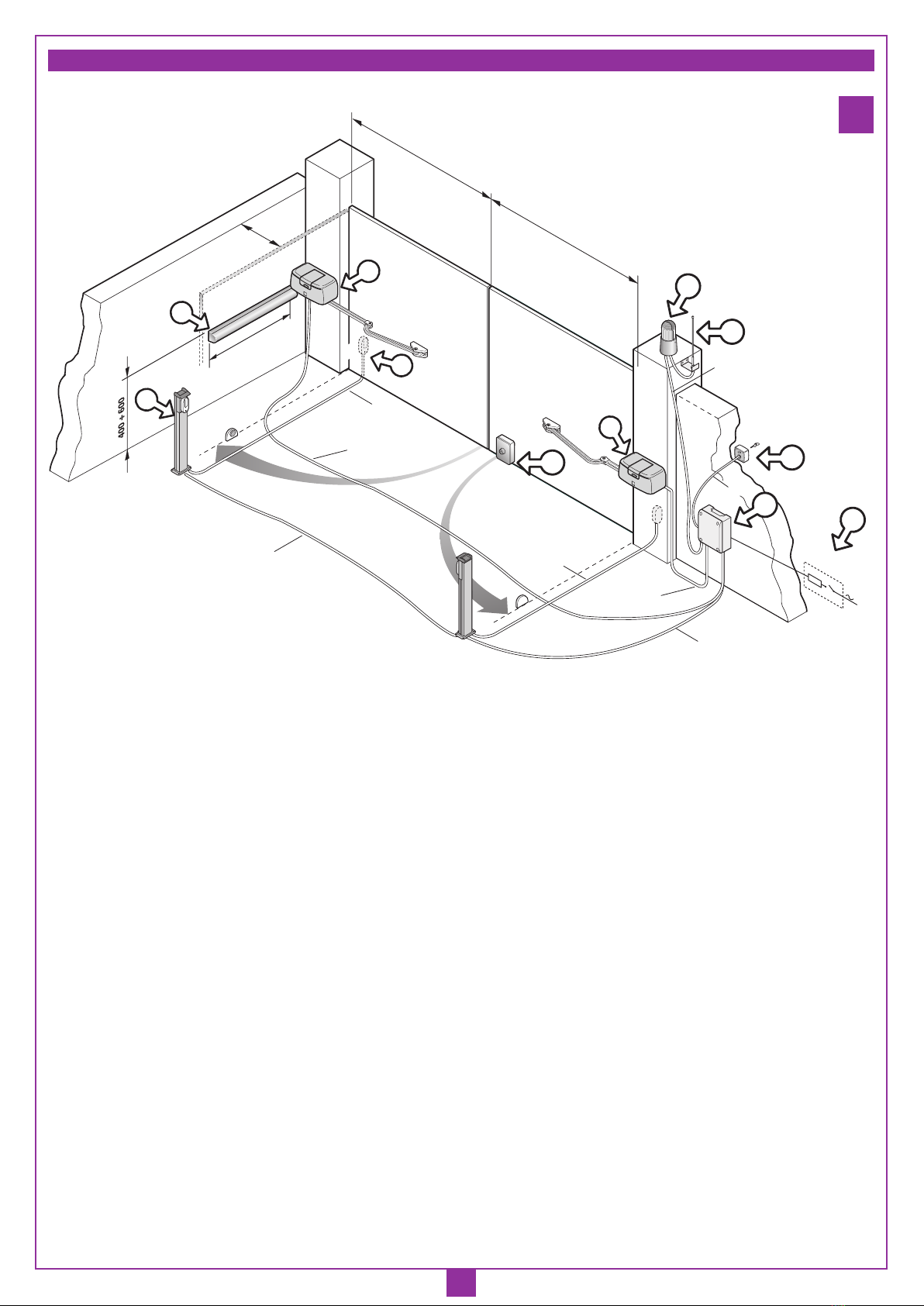
• Per il collegamento dei cavi elettrici all’apparecchiatura sono dispo-
nibili due ingressi:
- quello a muro "O" (fig.9);
- quello da esterno "P" (fig.9) tramite pressatubo, dopo aver sfondato
la parte in plastica che occlude il foro.
Per il buon funzionamento dell’apparecchiatura si racco-
manda di utilizzare esclusivamente programmatori elettronici
Cardin in corrente continua della serie PRG8511CC (con
batterie e senza caricabatterie) o PRG85110C (senza batterie
e senza caricabatterie) adatti all’azionamento di un motore
o due motori in parallelo.
L'operazione di sblocco va fatta solamente a motore fermo, per man-
canza di energia elettrica.
Per sbloccare l'anta del cancello munirsi della chiave in dotazione
all'apparecchiatura. Essa deve essere conservata in luogo di facile
reperimento.
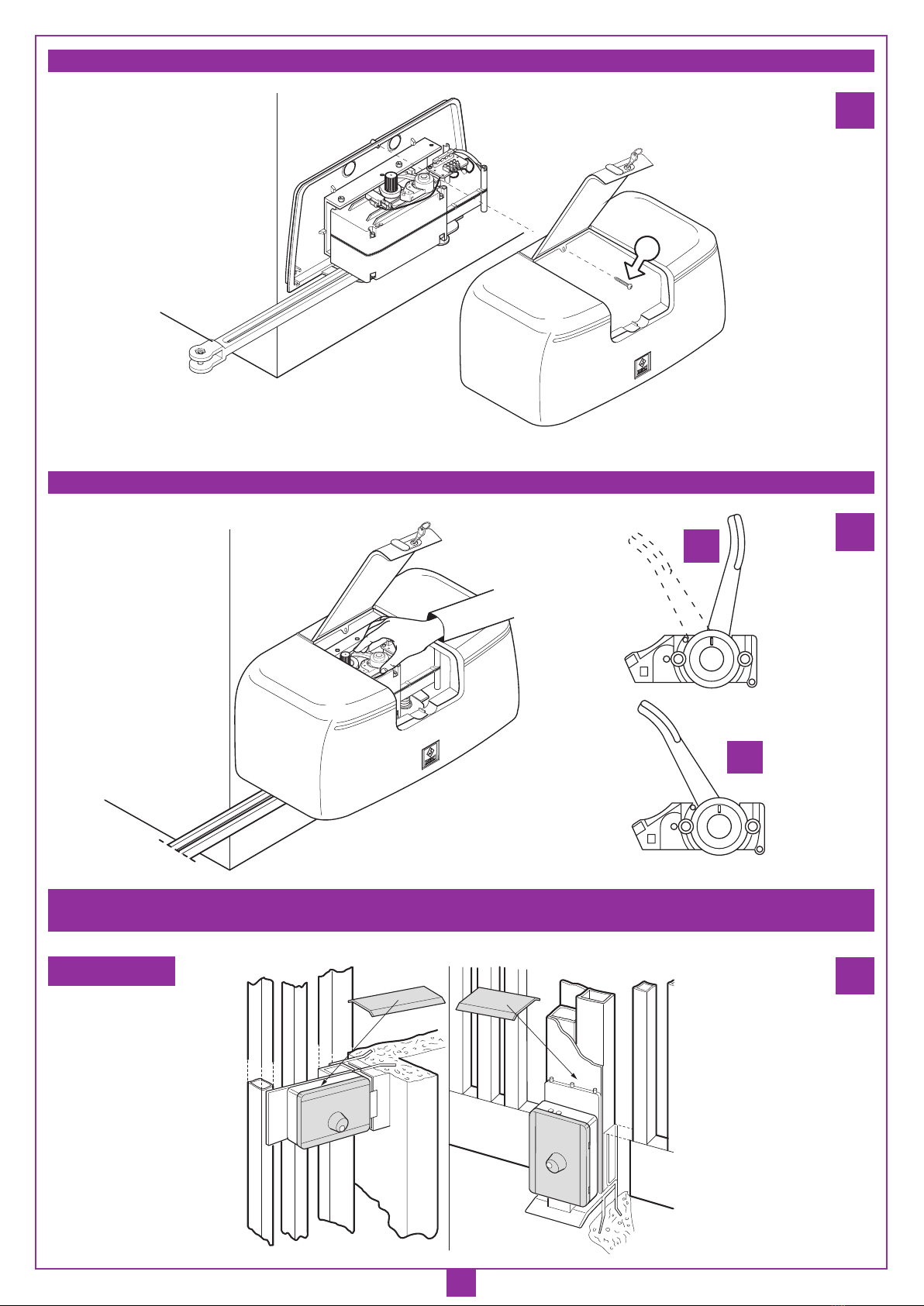
Per sbloccare
Aprire il portello e ruotare la leva in senso antiorario come indicato in
dett. "A" (fig. 12) fino a raggiungere la posizione di sblocco "B", dove
resterò agganciate grazie ad un fermo antiritorno. In questo modo si
rende folle l'ingranaggeria dell'attuatore e il cancello si potrà aprire e
chiudere con una leggera spinta a mano.
Per ribloccare
Forzare leggermente la leva dalla posizione di sblocco pos."B" in
cui si trova per vincere il fermo antiritorno che la mantiene in quella
posizione, nel verso opposto a quello di prima. Il ritorno alla posizione
bloccato "A" avviene automaticamente per effetto di una molla. Il
riaggancio dei denti dell’ingranaggeria all’interno del motoriduttore
può non essere immediato però può essere ottenuto o manualmente
spingendo sull’anta o alla riattivazione del motoriduttore.
Durante la manovra si deve controllare il movimento del cancello e
azionare il dispositivo di arresto immediato (STOP) in caso di pericolo.
In caso di emergenza il cancello può essere sbloccato manualmente
utilizzando l'apposita chiave di sblocco in dotazione (vedi sblocco
manuale).
Controllare periodicamente lo stato di usura dei perni ed eventual-
mente ingrassare le parti in moto, usando lubrificanti che mantengano
uguali caratteristiche di attrito nel tempo e adatti a funzionare tra -20
e +70°C.
In caso di guasto o anomalie di funzionamento staccare l'alimenta-
zione elettrica a monte dell'apparecchiatura e chiamare l'assistenza
tecnica.
Verificare periodicamente il funzionamento delle sicurezze (fotocellule
ecc.). Le eventuali riparazioni devono essere eseguite da personale
specializzato usando materiali originali e certificati.
FISSAGGIO DEL DISPOSITIVO
Il dispositivo può essere fissato sia alla sinistra che alla destra della
luce passaggio:
- nel caso di kit per due ante i motoriduttori sono già predisposti per
l'installazione a destra e a sinistra (vedi le etichette "SX" - "DX" sui
motori);
- nel caso di applicazioni su singola anta, la fornitura può essere
indifferentemente fatta con motoriduttori predisposti per applica-
zione a destra o a sinistra quindi controllare l'etichetta applicato sul
motore "SX" o "DX";
- nel caso che venga fornito un motore destro, mentre l'applicazione
verrà fatta a sinistra o viceversa, sarà necessario sfilare le camme
e reinserirle rovesciate (vedi fig. "9b" - "10b")
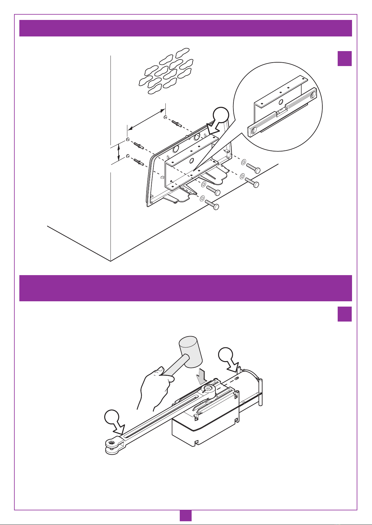
• Portare l'anta in posizione di chiuso.
• Scegliere la quota "A" in base all'angolo di apertura da ottenere
(fig. 4) e definire in base alle caratteristiche strutturali del cancello a
quale altezza andrà fissata la staffa anteriore al cancello. Una volta
individuata la posizione, fissare la base motore con 4 viti M8 e 4
tasselli in acciaio Ø14 avendo cura di mettere in bolla la staffa in
acciaio zincato "D" (fig. 7).
• Inserire il braccio dritto "E" nell'albero motore, come indicato in
figura 8, e fissarlo con la vite senza testa "F" avvitata a fondo.
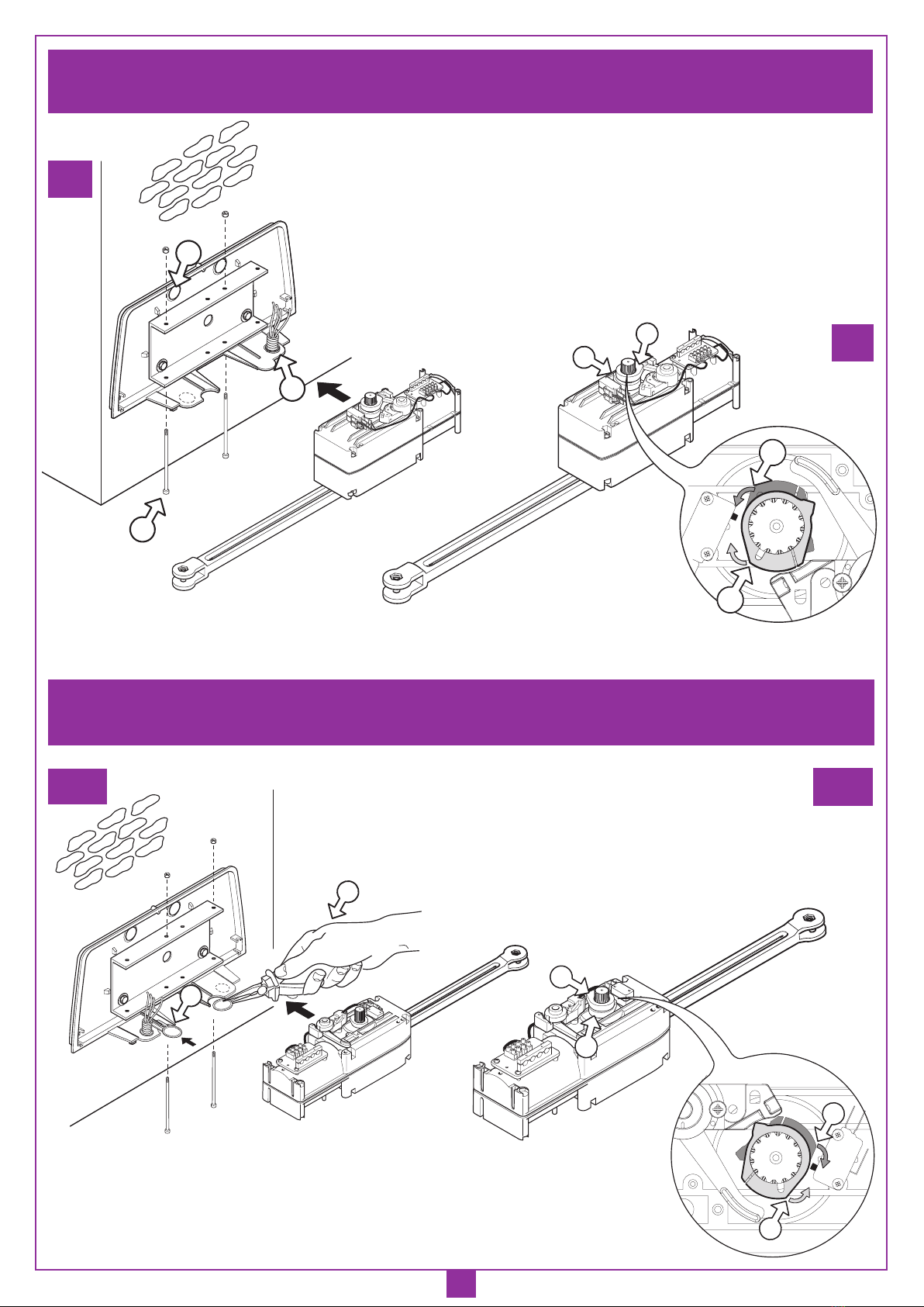
• Fissare il motoriduttore alla piastra base con le due viti "G" e rispettivi
dadi autobloccanti, rispettando lo schema di montaggio a destra
(fig.9) ed a sinistra (fig.10). Il motoriduttore viene fornito dalla fabbrica
previsto per il montaggio a destra del cancello (vista interna), per il
montaggio a sinistra si deve staccare la parte in plastica "H" (fig. 10)
che occlude il foro di passaggio dell'albero motore con l'ausilio di
una pinza ed otturare con il dischetto ad aggancio "L", in dotazione,
il foro rimasto inutilizzato.
• Procedere quindi con il montaggio del braccio articolato completo
di staffa di attacco al cancello (fig.2):
- inserire le boccole in plastica "11" nei fori del braccio curvo "7",
collegare il braccio curvo "7" al braccio dritto "6" e alla staffa "8"
entrambi con la vite "9" e dado autobloccante "12" dopo aver inserito
il distanziale zincato "10" all’interno della boccola "11".
• Sbloccare il motore (fig. 12).
• Fissare la staffa al cancello con 2 viti M8, 39 mm al di sotto della base
(dett.1 fig.6). La posizione della staffa viene determinata portando
il braccio alla massima estensione, con anta in battuta meccanica
di chiusura e punti 1,2,3 allineati (fig.4) sulla stessa retta, quindi
facendo arretrare il punto 2 di 100 mm dal punto di allineamento in
cui si trovava. Il braccio va tenuto in bolla "M" (fig.6).
Fare la seguente verifica:
- la staffa appoggiata al cancello, durante la rotazione del cancello
stesso dalla posizione chiuso alla posizione aperto, non deve subire
forzature lungo l'asse "L" (fig. 6) né verso l’alto né verso il basso
perchè in questo caso o il cancello, o il motoriduttore non sarebbero
stati montati correttamente e ciò potrebbe danneggiare in poco
tempo l'apparecchiatura. Una volta verificato che è ok, fissare la
staffa al cancello.
• Regolare il microinterruttore di finecorsa in chiusura (camma supe-
riore "A" fig. 9b-10b) e in apertura (camma inferiore "B" fig. 9b-10b):
per far ciò portare l'anta in apertura/chiusura fino alla posizione
desiderata, quindi far ruotare manualmente la camma fino allo scatto
del microinterruttore e quindi fissarla:
- i corretti punti di lavoro delle camme "A1"-"B1", per una
installazione a destra, sono indicati nel figura "9b".
- i corretti punti di lavoro delle camme "A1"-"B1", per una
installazione a sinistra, sono indicati nel figura "10b".
• Dopo aver effettuato le descritte operazioni di montaggio e dopo aver
effettuato il collegamento elettrico si può procedere alla chiusura
dell'apparecchiatura con l'applicazione del carter (fig.11). Esso va
fissato con la vite autofilettante "N" dopo aver controllato l'aggancio
dei due dentini inferiori di ritegno sulla base in plastica.
• È consigliato l’uso di un’elettroserratura (vedi impianto tipo fig.1)
COLLEGAMENTO ELETTRICO
(fig. 14)
SBLOCCO MANUALE (fig.12)
ISTRUZIONI PER L'USO