Cardin SL Series User manual

1
ITALIANO
ENGLISH
FRANÇAIS
DEUTSCH
ESPAÑOL
Preliminary checks/wiring diagram Pages 2-5
Important remarks Page 14
Installation instructions Page 14-15
Manual manoeuvre Page 16
Electrical connection Pages 16-17
Programming procedure Pages 18-20
Automatic repositioning Page 20
Remote control Page 20
Function modes Page 21
Battery powered operation Page 21
Technical specications Page 56
Contrôles avant le montage/schéma électrique Pages 2-5
Consignes importantes Page 22
Instructions pour l’installation Pages 22-23
Manœuvre manuelle Page 24
Branchement électrique Pages 24-25
Procédé de programmation Pages 26-28
Repositionnement Page 28
Commande par radio Page 28
Modes de fonctionnement Page 28
Fonctionnement à batterie Page 29
Caractéristiques techniques Page 56
Vorkontrollen/elektrischer Schaltplan Seiten 2-5
Wichtige Hinweise Seite 30
Installationsanleitung Seiten 30-31
Manuelle Betätigung Seite 32
Elektrischer Anschluss Seiten 32-33
Programmierverfahren Seiten 34-36
Neupositionierung Seite 36
Fernbedienung Seite 36
Betriebsart Seite 37
Batteriebetrieb Seite 37
Technische Eigenschaften Seite 56
Pruebas previas/esquema eléctrico Páginas 2-5
Advertencias importantes Página 38
Instrucciones para la instalación Páginas 38-39
Maniobra manual Página 40
Conexionado eléctrico Páginas 40-41
Procedimiento para la programación Páginas 42-44
Reposicionamiento Página 44
Mando vía radio Página 44
Modalidad de funcionamiento Página 45
Funcionamiento por batería Página 45
Características técnica Página 56
ZVL538.01 - Mod: 27-10-2016
AUTOMAZIONE PER CANCELLI SCORREVOLI CON MOTORE IN CORRENTE CONTINUA
AUTOMATION FOR SLIDING GATES WITH A DC POWERED MOTOR
AUTOMATISME POUR PORTAILS COULISSANTS AVEC MOTEUR À COURANT CONTINU
AUTOMATISIERUNG FÜR SCHIEBETORE MIT GLEICHSTROMMOTOR
AUTOMATIZACIÓN PARA CANCILLAS CORREDERAS CON MOTOR DE CORRIENTE CONTINUA
AUTOMATISERING VOOR SCHUIFPOORTEN MET EEN GELIJKSPANNINGSMOTOR
Veriche preliminari/schema elettrico Pagine 2-5
Avvertenze importanti Pagina 6
Istruzioni per l'installazione Pagina 6-7
Manovra manuale Pagina 8
Collegamento elettrico Pagine 8-9
Procedura di programmazione Pagina 10-12
Riposizionamento Pagina 12
Comando via radio Pagina 12
Modalità di funzionamento Pagina 13
Funzionamento a batteria Pagina 13
Caratteristiche tecniche Pagina 56
24Vdc
Motors
100/SLX324 V1.01
Questo prodotto è stato testato e collaudato nei laboratori della casa costruttrice, la quale ne ha verificato la
perfetta corrispondenza delle caratteristiche con quelle richieste dalla normativa vigente. This product has been
tried and tested in the manufacturer's laboratory who have verified that the product conforms in every aspect to
the safety standards in force. Ce produit a été testé et essayé dans les laboratoires du fabricant. Pour l'installer
suivre attentivement les instructions fournies. Dieses Produkt wurde in den Werkstätten der Herstellerfirma
auf die perfekte Übereinstimmung seiner Eigenschaften mit den von den geltenden Normen vorgeschriebenen
getestet und geprüft. Este producto ha sido probado y ensayado en los laboratorios del fabricante, que ha
comprobado la perfecta correspondencia de sus características con las contempladas
por la normativa vigente.
SL
24Vdc
Motors
Model Date
Instruction manual Series
SLX 324 12-06-2013
ZVL538.01
NEDERLANDS
Installatievoorbeeld/bedradingschema Pag. 2-5
Belangrijke opmerkingen Pag. 46
Installatie-instructies Pag. 46-47
Handmatige beweging Pag. 48
Elektrische aansluiting Pag. 48-49
Programmeerprocedure Pag. 50-52
Herpositionering Pag. 52
Afstandsbediening Pag. 52
Werkingsmodi Pag. 53
Bedrijf op batterijvoeding Pag. 53
Technische specicaties Pag. 56
CARDIN ELETTRONICA spa
Via del lavoro, 73 – Z.I. Cimavilla
31013 Codognè (TV) Italy
Tel: +39/0438.404011
Fax: +39/0438.401831
Http: www.cardin.it
S
4
4
9
-
-
-
S
4
8
6
-
-
-
S
5
0
8
-
-
-
S
5
0
4
-
-
-
Multi
Decoding

2
SL 24 Vdc
26-02-2013
DCE085
xxxxxxxxxxxxxxxxxxxxxxxxxxxxxxxxxxxxxxxxxxxxxxxxxxxxxxxxxx
xxxxxxxxxxxxxxxxxxxxxxxxxxxxxxxxxxxxxxxxxxxxxxxxxxxxxxxxx
xxxxxxxxxxxxxxxxxxxxxxxxxxxxxxxxxxxxxxxxxxxxxxxxxxxxxxxxxx
CARDIN ELETTRONICA spa
Via del lavoro, 73 – Z.I. Cimavilla
31013 Codognè (TV) Italy
Tel: +39/0438.404011
Fax: +39/0438.401831
Http: www.cardin.it
Il costruttore: CARDIN ELETTRONICA S.p.A.
DICHIARA CHE L'APPARECCHIATURA DESTINATA AD ESSERE INSERITA IN
MACCHINE E NON FUNZIONANTE IN MODO INDIPENDENTE
:
Nome dell'apparato Motoriduttore per cancelli scorrevoli
Tipo di apparato Automazione a 24 Vdc per cancelli scorrevoli fino a kg 3000
Modello SLX324 - SLX3024
Marchio Cardin Elettronica
Anno di prima fabbricazione -
MODELLO DATACODICE SERIE
Dichiarazione di Incorporazione
(Direttiva Macchine 2006/42/EC, All. IIB)
e sono state applicate le seguenti norme e/o specifiche tecniche:
- EN 55014-1 : 2006 + A1 + A2
- EN 55014-2 : 1997 + A1 :2001 + A2 :2008
- EN 61000-3-2 : 2006 + A1 + A2
- EN 61000-3-3 : 2013
- EN 301489-1 : V1.9.2
- EN 301489-3 : V1.6.1
- EN 60335-1 : 2011
- EN 60335-2 : 2003 + A11 2009
- EN 62233 : 2008
è conforme alle disposizioni delle seguenti direttive comunitarie:
- Direttiva 2014/30/EU (Compatibilità Elettromagnetica)
- Direttiva 2014/35/EU (Bassa Tensione)
- Direttiva 2014/53/EU (R&TTE)
DICHIARA CHE L'APPARECCHIATURA È IDEATA PER ESSERE INCORPORATA IN UNA MACCHINA O PER ESSERE ASSEMBLATA CON ALTRI
MACCHINARI PER COSTITUIRE UNA MACCHINA CONSIDERATA DALLA DIRETTIVA 2006/42/CE E SUCCESSIVI EMENDAMENTI.
INOLTRE DICHIARA CHE NON È CONSENTITO METTERE IN SERVIZIO L' APPARECCHIATURA FINO A CHE LA MACCHINA NELLA QUALE
SARÀ INCORPORATA E DELLA QUALE DIVENTERÀ COMPONENTE NON SIA STATA IDENTIFICATA E DICHIARATA LA CONFORMITÀ ALLE DI-
SPOSIZIONI DELLA DIRETTIVA 2006/42/CEE E SUCCESSIVI EMENDAMENTI.
Cardin Elettronica si impegna a trasmettere, in risposta a una richiesta adeguatamente motivata delle autorità nazionali, informazioni pertinenti sulla
quasi-macchina in oggetto.
Codognè il 22/03/2016
Persona autorizzata a costituire la documentazione tecnica
Ing. A. Fiorotto (Responsabile tecnico
R&D Laboratory)
Rappresentante legale dell'azienda
Dott. Cristiano Cardin (Amministratore delegato
)
La dichiarazione di conformità CE per i prodotti Cardin è disponibile in lingua originale nel sito www.cardin.it nella sezione "norme e certicazione" attraverso il link:
The CE conformity declaration for Cardin products is available in original language from the site www.cardin.it under the section "Standards and Certication" via the link:
Les déclarations de conformité CE des produits Cardin sont disponibles dans la langue originale sur le site www.cardin.it dans la section "normes et certicats" par le lien:
Die CE-Konformitätserklärungen für die Cardin-Produkte stehen in der Originalsprache auf der Homepage www.cardin.it im Bereich "Normen und Zertizierung" zur Verfügung unter dem Link:
Las declaraciones de conformidad CE de los productos Cardin se encuentran disponibles en el idioma original en el sitio www.cardin.it en la secci—n "normas y certicaciones” en el enlace:
http://www.cardin.it/Attachment/dce085.pdf

3
SCALA:
Prodotti Technocity
SL
24-05-99
DI0128 Description :
Product Code :
Date :
Drawing number :
P.J.Heath
CARDIN ELETTRONICA S.p.A - 31020 San Vendemiano (TV) Italy - via Raffaello, 36 Tel: 0438/401818 Fax: 0438/401831
Draft :
All rights reserved. Unauthorised copying or use of the information contained in this document is punishable by law
IMPIANTO A NORME STRUTTURA SL
H
I
L
M
B
F
D
B
N
P
A
C
G
O
A
G
Q
O
C
D
E
30-40 mm
VERIFICHE PRELIMINARI - PRELIMINARY CHECKS - CONTRÔLES À EFFECTUER AVANT LE MONTAGE
VORKONTROLLEN - PRUEBAS PREVIAS -CONTROLES VOORAF
LEGENDA
A Supercie anta cancello
B Distanza tra parti sse e mobili
C Guida di scorrimento
D Distanza di sicurezza
E Arresto meccanico in chiusura
F Elemento elastico deformabile
G Recinzione
H Distanza tra recinzione e cancello
I Rete o griglia
L Traforato metallico
M Sfera di prova passaggio
N Livella a bolla
O Pattini o rulli guida
P Corsa cancello
Q Arresto meccanico in apertura
LEGEND
A Gate surface
B Distance between the xed and moving parts
C Castor guide
D Safety distance
E Closing mechanical travel limit
F Rubber anticrush buffer
G Fencing
H Distance between the fence and the gate
I Wire mesh
L Punched metal plate
M Test sphere
N Spirit level
O Runner guide
P Gate travel distance
Q Opening mechanical travel limit
NOMENCLATURE
A Surface du portail
B Distance entre parties xes et mobiles
C Rail de guidage
D Distance de sécurité
E Butée en fermeture
F Élément élastique déformable
G Clôture
H Distance entre clôture et portail
I Grillage ou grille
L Panneau métallique perforé
M Bille d'essai de passage
N Niveau à bulle
O Patins ou galets de guidage
P Course portail
Q Butée en ouverture
ZEICHENERKLÄRUNG
A Torügeloberäche
B Abstand zwischen festen und beweglichen Teilen
C Gleitschiene
D Sicherheitsabstand
E Mechanischer Anschlag bei Schließung
F Verformbares elastisches Element
G Gitter
H Abstand zwischen Gitter und Torügel
I Drahtgeecht oder Gitterwerk
L Lochblech
M Prüfkugel
N Wasserwaage
O Gleitschuhe oder Führungsrollen
P Torügellaufstrecke
Q Mechanischer Endanschlag bei Öffnung
LEYENDA
A Supercie cancilla
B Distancia entre piezas jas y móviles
C Guía de deslizamiento
D Distancia de seguridad
E Tope mecánico en fase de cierre
F Elemento elástico deformable
G Cercado
H Distancia entre cercado y cancilla
I Red de alambre o cancilla
L Elemento metálico agujereado
M Bola de prueba paso
N Nivel de burbuja
O Patines o rodillos de guía
P Carrera cancilla
Q Tope mecánico en fase de apertura
1
LEGENDE
A Poortoppervlak
B Afstand tussen het vaste deel en de bewegende delen
C Loopwielgeleiding
D Veiligheidsafstand
E Mechanische sluitbewegingsbegrenzing
F Rubberen persoonsbeveiligingsbuffer
G Hekwerk
H Afstand tussen het hek en de poort
I Gaas mat
L Geperforeerde metalen plaat
M Testkogel
N Waterpas
O Geleideportaal
P Poortbewegingsafstand
Q Mechanische openingsbewegingsbegrenzing

4
prodotti Technocity (lamp. fotocellule ecc.)
04-09-2006
DI0449 Description :
Product Code :
Date :
Drawing number :
P.J.Heath
CARDIN ELETTRONICA S.p.A - 31020 San Vendemiano (TV) Italy - via Raffaello, 36 Tel: 0438/401818 Fax: 0438/401831
Draft :
All rights reserved. Unauthorised copying or use of the information contained in this document is punishable by law
INSTALLAZIONE TIPO SL1524
TX
RX
7
5
230V - 50 HZ
6
1
3
4
8
9
10
2
SL1524
ESEMPIO D'INSTALLAZIONE - INSTALLATION EXAMPLE - EXEMPLE D'INSTALLATION
ANLAGENART - INSTALACIÓN ESTÁNDAR - INSTALLATIEVOORBEELD
2
LEGENDA
1 Motoriduttore
2 Fotocellula interna
3 Fotocellula esterna
4 Costa sensibile
5 Lampeggiatore
6 Selettore a chiave
7 Antenna esterna (cavo coassiale RG58 Impedenza 50Ω)
8 Cavo alimentazione principale 230 Vac
9 Interruttore onnipolare con apertura contatti min. 3 mm
10 Canalatura per collegamenti a bassa tensione
Attenzione: Lo schema rappresentato è puramente indicativo e
viene fornito come base di lavoro al ne di consentire una scelta
dei componenti elettronici Cardin da utilizzare. Detto schema non
costituisce pertanto vincolo alcuno per l'esecuzione dell'impianto
LEGEND
1 Geared motor
2 Internal photocells
3 External photocells
4 Contact safety edge
5 Warning lights
6 Mechanical selector switch
7 External antenna (RG58 coaxial cable - impedance 50Ω)
8 Mains cable 230 Vac
9 All pole circuit breaker (3 mm min. between the contacts)
10 Channelling route for low voltage wires
Attention: The drawing is purely indicative and is supplied as
working base from which to choose the Cardin electronic compo-
nents making up the installation. This drawing therefore does not
lay down any obligations regarding the execution of the installation.
NOMENCLATURE
1 Motoréducteur
2 Cellule photoélectrique intérieure
3 Cellule photoélectrique extérieure
4 Bord de sécurité
5 Clignoteur
6 Contact à clé
7 Antenne externe (câble coaxial RG58 impédance 50Ω)
8 Câble d’alimentation principale 230 Vac
9 Interrupteur omnipolaire (ouverture contacts d'au moins 3 mm)
10 Chemin pour branchement basse tension
Attention: ce schéma, diffusé à titre purement indicatif, est destiné
à vous aider dans le choix des composants électroniques Cardin à
utiliser. Par conséquent, il n'a aucune valeur obligatoire quant à la
réalisation de l'installation.
ZEICHENERKLÄRUNG
1 Getriebemotor
2 Interne Lichtschranke
3 Externe Lichtschranke
4 Kontaktleiste
5 Blinklicht
6 Schlüsselschalter
7 Außenantenne (Koaxialkabel RG58 Impedanz 50Ω)
8 Hauptversorgungskabel 230 Vac
9 Allpoliger Schalter (Kontaktabstand von mindestens 3 mm)
10 Kanalverlauf für Anschluss auf Niederspannung
Achtung: Bei dem dargestellten Plan handelt es sich nur um
ungefähre Angaben und er wird als Arbeitsgrundlage geliefert, um
eine Auswahl der zu benutzenden elektronischen Komponenten von
Cardin zu erlauben. Der besagte Plan ist daher für die Ausführung
der Anlage nicht bindend.
LEYENDA
1 Motorreductor
2 Fotocélula interior
3 Fotocélula exterior
4 Banda sensible
5 Relampagueador
6 Selector con llave
7 Antena exterior (Cable coaxial RG58 Impedancia 50Ω)
8 Cable de alimentación principal 230 Vac
9 Interruptor omnipolar (apertura entre los contactos de mín. 3 mm)
10 Canaleta para el conexionado a baja tensión
Atención: La pantalla que se muestra es sólo indicativa y se suministra
como base de trabajo, con el n de permitir una elección de los compo-
nentes electrónicos Cardin por utilizar; en consecuencia, dicho esquema
no constituye vínculo alguno para la ejecución del sistema.
LEGENDE
1 Tandwielmotor
2 Inwendige fotocellen
3 Uitwendige fotocellen
4 Persoonsbeveiligingsproel
5 Waarschuwingslampen
6 Mechanische keuzeschakelaar
7 Externe antenne (RG58 coaxkabel - impedantie 50Ω)
8 Netsnoer 230 Vac
9 Alpolige uitschakelaar met minimaal 3 mm tussen de contacten
10 Goot voor laagspanningsbedrading
Let op: Deze tekening dient puur als globale referentie voor het selecteren van de elektronische componenten van Cardin waaruit de
installatiewordtsamengesteld. Deze tekening legt derhalve geen verplichtingen op met betrekking tot de uitvoering van de installatie.

5
Collegamenti scheda base
CC1524
31.01.12
DI0592 Description :
Product Code :
Date :
Drawing number :
P.J.Heath
CARDIN ELETTRONICA S.p.A - 31020 San Vendemiano (TV) Italy - via Raffaello, 36 Tel: 0438/401818 Fax: 0438/401831
Draft :
All rights reserved. Unauthorised copying or use of the information contained in this document is punishable by law
CENTRALINA 1 MOTORE CC CON ENCODER
SEL
1
32
24V 12V 0
C
1
65432
NA
NC NC
C
NA
FTC-RX
1
32
24V
12V
0
FTC-TX
2
1
TB
2
1
LP
1
2
LS
2
1
CSP
CTRL 24Vdc
CMN
CMN
TD (N.O)
CMN
TC (N.O)
TAL (N.O)
LP
LS
OUT 24Vdc
9 10 11 12 13 14 15 16 17 18 19 20 21 22 23 24 25 26
LC/CH2
L2
31
30
29
CMN
EMRG 1
EMRG 2
8
1 4 5 6 7
ENCODER
CMN
CMN
TA (N.O)
F1
10
10
4A
4A
F3
F2
10
10
F4
4A
4A
J2
J1
R1 MM
27 28
CS 1392A
DC 0449
L1
P1 P2 P3
ANS400
MM
24LC16
FI (N.C/8.2 kΩ)
TB (N.C/8.2 kΩ)
FS (N.C/8.2 kΩ)
CP (N.C/8.2 kΩ)
B1
BC
J3
Enable
Disable
123
J3
Pos.1 Pos.2
123
BkRd
MOT
PROGRAM
00.000.007
07-06-13 15.35
TB
FI
FS
CP
TA
TD
TC
TAL
2 3
+ -
SCHEMA ELETTRICO - STANDARD WIRING - SCHÉMA ÉLECTRIQUE - ELEKTRISCHER SCHALTPLAN
ESQUEMA ELÉCTRICO - BEDRADINGSCHEMA
3
Collegamento alimentazione generale 230 Vac
Mains power supply connection 230 Vac
Branchement alimentation générale 230 Vac
Anschluss allgemeine Stromversorgung 230 Vac
Conexión alimentación general 230 Vac
Netvoeding 230 Vac
N
L
Fissaggio placca inferiore
06-03-95
DI0286 Description :
Product Code :
Date :
Drawing number :
P.J.Heath
CARDIN ELETTRONICA S.p.A - 31020 San Vendemiano (TV) Italy - via Raffaello, 36 Tel: 0438/401818 Fax: 0438/401831
Draft :
All rights reserved. Unauthorised copying or use of the information contained in this document is punishable by law
Collegamento motore

6
• Il presente manuale si rivolge a persone abilitate all'installazione di "apparecchi
utilizzatori di energia elettrica" e richiede una buona conoscenza della tecnica,
esercitata in forma professionale e della normativa vigente.
I materiali usati devono essere certicati e risultare idonei alle condizioni ambientali
di installazione e operazioni di manutenzione devono essere eseguite da personale
qualicato.
• Le apparecchiature qui descritte dovranno essere destinate solo all'uso per il quale
sono state espressamente concepite: "La motorizzazione di cancelli scorrevoli"
no a 3000 kg peso anta.
Attenzione! È assolutamente obbligatoria la presenza delle
battute antideragliamento.
• Questo apparecchio non deve essere utilizzato da persone (bambini compresi) con ri-
dotte capacità siche, sensoriali o mentali, oppure mancanza di esperienza o di conos-
cenza, a meno che esse abbiano potuto beneciare, attraverso l’intermediazione di una
persona responsabile della loro sicurezza, di una sorveglianza o di istruzioni riguardanti
l’utilizzo dell’apparecchio.
• Prima dell’installazione, vericare che la parte guidata sia in buone condizioni, bilanciata
correttamente e che la chiusura e l’apertura avvengano in modo corretto.
• Evitare il rischio di intrappolamento tra la parte guidata e le parti sse circostanti durante
i movimenti di apertura e chiusura.
• Il cavo di alimentazione del motore deve essere in policloroprene conforme alla desig-
nazione 60245 IEC 57.
È responsabilità dell’installatore vericare le seguenti condizioni di sicurezza:
1) L’installazione deveessere sufcientemente lontanadalla stradain modo danon costituire
pericolo per la circolazione.
2) L’operatore deve essere installato all’interno della proprietà ed il cancello non deve aprirsi
verso l’area pubblica.
3) Il cancello motorizzato è principalmente adibito al passaggio di
vetture e non deve essere utilizzata con una porta pedonale.
4) Icomandi(compresiquellidiemergenza)devonoesserepostiinvista,
ad un'altezza compresa tra 1,5 m e 1,8 m, ma non entro il raggio
d’azionedelcancello.Inoltrequelliinstallatiall’esternodevonoessere
protetti da una sicurezza tale da prevenire l’uso non autorizzato.
5) Non permettere ai bambini di giocare con l'apparecchiatura o con
i comandi dell'automazione.
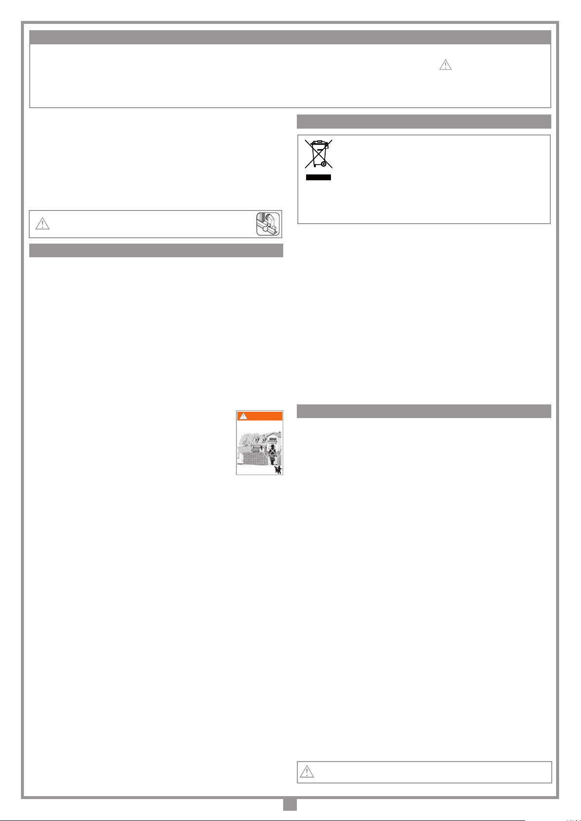
6) È buona norma segnalare l’automazione con targhe di avvertenza (simili a quella in gura)
che devono essere facilmente visibili. Qualora l’automazione sia adibita al solo passaggio
di veicoli dovranno essere poste due targhe di avvertenza di divieto di transito pedonale
(una all’interno, una all’esterno).
7) A monte dell'automazione deve essere installato un dispositivo di sezionamento che
assicuri la disconnessione onnipolare dalla rete di alimentazione, con un a distanza di
apertura dei contatti che consente la disconnessione completa nella condizioni della
sovratensione (categoria III), conformemente alle regole di installazione nazionale.
8) La bontà della connessione di terra dell’apparecchiatura è fondamentale ai ni della
sicurezza elettrica.
9) Per qualsiasi dubbio a riguardo della sicurezza dell’installazione, non procedere ma
rivolgersi al distributore del prodotto.
DESCRIZIONE TECNICA
- Alimentazione generale 230 Vac
-Motore alimentato con tensione max 37 Vdc.
- Carter superiore in materiale plastico antiurto ad alta resistenza.
- Cassa del riduttore in alluminio pressofuso. All'interno opera un sistema di riduzione a
vite senza ne a doppia riduzione con lubricazione a grasso uido permanente.
- Sistema di riduzione irreversibile con sblocco manuale a chiave.
- Programmatore elettronico incorporato completo di parte di potenza, logica di controllo,
carica batterie e sistema radio ricevente.
L’alimentazionevienefornita alla schedadauntrasformatoretoroidaleseparato,alloggiato
nello stesso contenitore e collegato alla scheda tramite Faston.
- Il sistema è dotato di controllo elettronico in frenata, riducendo al minimo gli urti di arresto
dovuti all'inerzia del cancello.
Accessori
106/CRENY - Cremagliera in bra di vetro 20 mm x 30 mm con asole sopra (1 m)
106/CRENY1 - Cremagliera in bra di vetro 20 mm x 30 mm con asole sotto (1 m)
106/SLOAC - Cremagliera in acciaio zincato 20 mm x 22 mm a saldare (2 m)
106/SLOAC2 - Cremagliera in acciaio zincato 12 mm x 30 mm con asole (1 m)
950/NC8K2L - Costa meccanica sensibile, lunghezza da 1,6 a 3,0 m x h 61 mm.
Q
Attenzione! Solo per clienti dell’EU - Marcatura WEEE.
Il simbolo indica che il prodotto alla ne della propria vita utile deve essere raccolto
separatamente dagli altri riuti. L’utente dovrà pertanto conferire l’apparecchiatura
agli idonei centri di raccolta differenziata dei riuti elettronici ed elettrici, oppure
riconsegnarla al rivenditore al momento dell’acquisto di una nuova apparecchiatura
di tipo equivalente, in ragione di uno a uno.
L’adeguata raccolta differenziata per l’avvio al riciclaggio, al trattamento e allo smaltimento
ambientalmente compatibile contribuisce ad evitare possibili effetti negativi sull’ambiente e
sulla salute e favorisce il riciclo dei materiali. Lo smaltimento abusivo del prodotto da parte del
detentore comporta l’applicazione delle sanzioni amministrative previste dalla normativa vigente
nello Stato Comunitario di appartenenza.
Durante la manovra si deve controllare il movimento e azionare il dispositivo di arresto
immediato (STOP) in caso di pericolo.
Attenzione! Pericolo di Intarppolamento. Nell’uso del dispositivo si consiglia di aspettare
la completa apertura del cancello prima di attraversarlo e di prestare la massima attenzione
al pericolo di intrappolamento tra cremagliera e le parti sse del installazione.
In caso di mancanza di energia elettrica e con la batteria scarica il cancello può essere
sbloccato manualmente utilizzando l'apposita chiave di sblocco in dotazione (vedi sblocco
manuale g. 8).
Manutenzione periodica
Prima di eseguire qualsiasi operazione di pulizia o di manutenzione, disinserire l'appa-
recchiatura dalla rete di alimentazione elettrica, staccare l'alimentazione del motore e
scollegare le batterie.
Controllare periodicamente lo stato di usura dei perni ed eventualmente ingrassare le parti
in moto (perni, cremagliera ecc), usando lubricanti che mantengano uguali caratteristiche
di attrito nel tempo e adatti a funzionare tra -20 e + 70°C.
Le eventuali riparazioni devono essere eseguite da personale specializzato usando materiali
originali e certicati.
L'uso dell'automazione non è idoneo all'azionamento in continuo, bensì deve essere
contenuto al 70%.
Prima di procedere all'esecuzione dell'impianto vericare che la struttura da automatizzare sia in
perfetta efcienza nelle sue parti sse e mobili e realizzata in conformità alla normativa vigente.
A tal ne accertarsi che:
- La supercie dell’anta scorrevole "A" sia liscia e senza sporgenze, no all’altezza di 2.5 m dal
suolo. Possono intendersi liscie anche sporgenze dalla supercie no a 3 mm purché con bordi
arrotondati. Se la supercie dell’anta non è liscia, tutta la sua altezza, no al limite di 2.5 m dal
suolo, dovrà essere protetta con i seguenti dispositivi:
a) fotocellule
b) costa sensibile
- lo spazio "B" tra parti fisse e parti scorrevoli non deve essere maggiore di 15 mm.
- la guida di scorrimento "C", preferibilmente di sezione tonda, deve essere ssata al suolo in
modo stabile e indeformabile, completamente esposta e priva di imperfezioni che possano
ostacolare il movimento del cancello.
- a cancello chiuso deve restare uno spazio libero "D", per tutta l’altezza della parte anteriore
del cancello, di almeno 50 mm mentre la battuta meccanica "E" di ne corsa in chiusura deve
essere posta sulla parte superiore del cancello.
- lo spazio libero "D" può essere ricoperto da un elemento elastico deformabile "F" o meglio da
una costa di sicurezza.
- se durante il movimento di apertura, il cancello scorre vicino ad una cancellata "G" ad elementi
verticali o con luci libere provvedere all’installazione di una protezione adeguata secondo il
caso:
1. Distanza "H" maggiore di 500 mm: nessuna protezione;
2. Distanza "H" compresa tra 500 e 300 mm: applicazione di una rete "I" o di un traforato
metallico "L" avente aperture che non permettano il passaggio di una sfera "M" del diametro
di 25 mm;
3. Distanza "H" minore di 300 mm: applicazione di una rete "I" o di un traforato metallico "L"
aventi aperture che non permettano il passaggio di una sfera "M" del diametro di 12 mm.
I li delle reti "I" non devono avere sezione minore di 2,5 mm2e i traforati metallici "L" non
devono avere spessore minore di 1,2 mm. Oltre il limite di 2,5 m dal suolo per il tratto "P"
di scorrimento del cancello tali protezioni non sono necessarie.
- vericare lo stato di usura di eventuali parti vecchie, consumate del cancello e se necessario
provvedere alla loro sostituzione e lubricazione.
- vericare la messa in bolla "N" della guida.
- i pattini o rulli di guida superiori "O" devono presentare un giusto gioco allo scorrimento dell’anta
e in nessun caso ostacolare la sua corsa.
- verificare l’esistenza, assolutamente necessaria, di una battuta di arresto "Q" mecca-
nico in apertura in corrispondenza della massima corsa "P", tale da garantire la stabi-
lità del cancello e quindi di evitare il pericolo di sgancio dai rulli di guida superiori "O".
Attenzione! È comunque cura dell’installatore vericare i punti critici, di pericolo, e prendere
gli opportuni provvedimenti ai ni della sicurezza e dell’incolumità personale (analisi dei rischi).
ATTENZIONE! IMPORTANTI ISTRUZIONI DI SICUREZZA
CONSIDERAZIONI GENERALI DI SICUREZZA
VERIFICHE PRELIMINARI (fig. 1, pag. 2)
APERTURA AUTOMATICA
NON AVVICINARSI
NON PERMETTERE A BAMBINI O AD
ANIMALI DOMESTICI DI SOSTARE NEL
RAGGIO D'AZIONE DEL CANCELLO
ATTENZIONE
È IMPORTANTE PER LA SICUREZZA DELLE PERSONE SEGUIRE QUESTE ISTRUZIONI: LEGGERE ATTENTAMENTE LE SEGUENTI AVVERTENZE
PRIMA DI PROCEDERE ALL’INSTALLAZIONE. PRESTARE PARTICOLARE ATTENZIONE A TUTTE LE SEGNALAZIONI DISPOSTE NEL TESTO DI
QUESTO LIBRETTO D'ISTRUZIONI ORIGINALE. IL MANCATO RISPETTO DI QUESTE POTREBBE COMPROMETTERE IL BUON FUNZIONAMENTO
DEL SISTEMA E CREARE SITUAZIONI DI PERICOLO GRAVE PER L'OPERATORE E GLI UTILIZZATORI DEL SISTEMA STESSO. CONSERVARE QUESTE
ISTRUZIONI PER OGNI FUTURO RIFERIMENTO.
AVVERTENZE PER L'UTENTE

7
Dimensioni d'ingombro e posizionamento del gruppo
• Il motoriduttore deve essere installato rispettando il corretto posizionamento: perpendicolare al terreno, in piedi su supercie piana.
ISTRUZIONI PER L’INSTALLAZIONE
4
7
SCALA: 1:2
SL1524
23.04.2009
DI0532 Description :
Product Code :
Date :
Drawing number :
P.J.Heath
CARDIN ELETTRONICA S.p.A - 31020 San Vendemiano (TV) Italy - via Raffaello, 36 Tel: 0438/401818 Fax: 0438/401831
Draft :
All rights reserved. Unauthorised copying or use of the information contained in this document is punishable by law
6934
157
Vista in pianta e di fianco senza motore
25
110
104,5
50325
SCALA: 1:2
Prodotti Technocity
SL1524
08-02-2002
DI0240 Description :
Product Code :
Date :
Drawing number :
P.J.Heath
CARDIN ELETTRONICA S.p.A - 31020 San Vendemiano (TV) Italy - via Raffaello, 36 Tel: 0438/401818 Fax: 0438/401831
Draft :
All rights reserved. Unauthorised copying or use of the information contained in this document is punishable by law
VISTA DI FIANCO CON MOTORE
25 15
2 mm
325
ANCORAGGIO
visuale in pianta
ANCORAGGIO
visuale laterale
Ancoraggio del motoriduttore (g. 6, 7)
Importante! Vericare la posizione di ancoraggio rispetto alla linea di scorrimento del cancello.
• Preparare tubi e cavi di collegamento portandoli al punto d'installazione motore (vedi g. 2).
• Avvitare le quattro zanche di ancoraggio alla piastra "A" con 50 mm sporgenti e serrare i bulloni M12.
• Preparare una piazzola di cemento con una profondità di 350 mm (25 mm sporgente per evitare che accumuli
d'acqua possano danneggiare l’apparecchiatura) nel punto esatto dove è previsto il posizionamento del motore.
• Inserire la piastra di base avendo cura che:
- i cavi di collegamento passino attraverso il foro "B";
- le zanche "C" anneghino nella piazzola lasciando tutto perfettamente in bolla;
- i quattro gambi lettati sporgenti 50 mm siano perfettamente perpendicolari;
- la supercie della piastra sia pulita e senza residui di cemento.
Se la guida di scorrimento è già esistente, la piazzola di cemento deve essere ricavata in parte anche nel getto di
fondazione della guida stessa. Tale accorgimento elimina la possibilità che le due strutture cedano in modo diverso.
• Svitare i quattro dadi M12 sui quattro gambi lettati (precedentemente utilizzati per bloccare le zanche) dalla
piastra di base.
• Posizionare il motoriduttore sui quattro gambi lettati e farlo appoggiare sulla contropiastra.
• Renderlo quindi solidale alla base utilizzando quattro rondelle e altrettanti dadi in dotazione, curando che il
gruppo rimanga in bolla e sia perfettamente stabile.
• Regolare l'altezza del gruppo utilizzando i quattro grani presenti sul motore.
Questo accorgimento permetterà tutte le regolazioni successive alla posa.
Montaggio cremagliera
• Sbloccareilmotoriduttore(g. 8),appoggiare
il primo elemento di cremagliera sul pignone
e ssarlo all'anta.
Poi spostando l'anta procedere così con
gli altri elementi di cremagliera per tutta la
lunghezza dell'anta.
• Ultimato il fissaggio della cremagliera,
regolare il gioco pignone-cremagliera (1-2
mm) agendo sui grani posti alla base del
motoriduttore; in modo che il peso dell’anta
non vada a gravare sul motoriduttore, cosa
che non deve mai succedere.
256
56
30
118
170 170
SCALA: 1:2
Prodotti Cardin
SLX324
06-02-2002
DI0546 Description :
Product Code :
Date :
Drawing number :
P.J.Heath
CARDIN ELETTRONICA S.p.A - 31020 San Vendemiano (TV) Italy - via Raffaello, 36 Tel: 0438/401818 Fax: 0438/401831
Draft :
All rights reserved. Unauthorised copying or use of the information contained in this document is punishable by law
Dimensioni d'ingombro
360
340
SCALA: 1:2
Prodotti Technocity
SL324
14-02-2005
DI0365 Description :
Product Code :
Date :
Drawing number :
P.J.Heath
CARDIN ELETTRONICA S.p.A - 31020 San Vendemiano (TV) Italy - via Raffaello, 36 Tel: 0438/401818 Fax: 0438/401831
Draft :
All rights reserved. Unauthorised copying or use of the information contained in this document is punishable by law
VISTA INTERNA CANCELLO SL1524
5
Cancello
Piastra
Cremagliera
perpendicolare al terreno
SCALA: 1:2
Prodotti Technocity
SL1524M
30-01-2002
DI0237 Description :
Product Code :
Date :
Drawing number :
P.J.Heath
CARDIN ELETTRONICA S.p.A - 31020 San Vendemiano (TV) Italy - via Raffaello, 36 Tel: 0438/401818 Fax: 0438/401831
Draft :
All rights reserved. Unauthorised copying or use of the information contained in this document is punishable by law
CONTROPIASTRA SL1524M
M12
50 mm
312
31
54 34
157
69
43
A
B
C
Grindkant - Strana vrat - Grindsida
portail
279
6
- Il motoriduttore è assemblato in fabbrica per essere installato a
SINISTRA del cancello (visto dall’interno). Per l'installazione a destra
impostare il parametro installazione motore (pagina 10).

8
L'operazione di sblocco va fatta a motore fermo. Per sbloccare l'anta del cancello
munirsi della chiave in dotazione all'apparecchiatura. Essa deve essere conservata
in luogo di facile reperimento.
SBLOCCO A VITE
Operazione di sblocco (fig. 8)
1. Ruotare il copri serratura, inserire la chiave, ruotarla di mezzo giro in
senso antiorario ed alzare la protezione sblocco. La manopola è libera
di sbloccare.
2. Ruotare la manopola in senso orario, compiendo più giri, no alla ne
della sua corsa. Il riduttore è sbloccato ed il cancello è libero di scorrere
manualmente.
Attenzione! Non forzare la manopola oltre il necorsa.
Ribloccaggio (fig. 8)
1. Ruotare la manopola “D” in senso antiorario no a bloccarlo completa-
mente.
Attenzione! Non forzare la manopola oltre il necorsa.
2.
Chiudere la protezione sblocco, ruotare la chiave in senso orario e ruotare
il copri serratura.
Il riduttore è bloccato ed il cancello è pronto per l'uso.
A sistema ripristinato riporre la chiave in un luogo sicuro.
Attenzione! Non usare lo sblocco durante il normale funzionamento del
cancello. Lo spostamento manuale del cancello causa la perdita della
posizione da parte dell'encoder. Per ripristinare il controllo, dopo aver
ribloccato l'anta, sarà necessario dare 3 o più comandi di moto afnchè
l'anta, trovando la battuta più volte, possa posizionarsi correttamente.
Accesso al quadro di comando
Attenzione! Prima di accedere al quadro
di comando assicurarsi di aver disinserito
l’interruttore generale a monte dell’appa-
recchiatura.
Per accedere al motore allentare le due viti
"A" poste alle estremità laterali del coperchio
come indicato in gura 9.
Programmatore per motore in corrente continua con ricevente incorporata, che per-
mette la memorizzazione di 300 / 1000 codici utente (vedere "comando via radio", a
pag. 11). La decodica è di tipo 'rolling code', e la frequenza di funzionamento è di
433.92 MHz (868 MHz su richiesta).
La velocità di rotazione del motore è controllata elettronicamente, con partenza lenta
e successivo incremento; la velocità viene ridotta con anticipo rispetto all'arrivo in
battuta, in modo da ottenere un arresto controllato.
La programmazione, eseguibile mediante un solo pulsante, permette la congurazione
del sistema, del sensore di sforzo e della corsa totale dell'anta.
La logica esegue un controllo di posizione tramite encoder.
L’intervento del sensore antischiacciamento/anticonvogliamento causa una breve
(10 cm) inversione del moto e poi il blocco.
Attenzione! In nessun punto della scheda del programmatore è presente
la tensione a 230 Vac: si ha solamente la bassissima tensione di sicu-
rezza. Per la conformità alla normativa sulla sicurezza elettrica, è proibito
collegare i morsetti 9e 10 direttamente ad un circuito dove sia applicata
una tensione superiore a 30 Vac/dc.
Attenzione!Perilcorrettofunzionamentodelprogrammatore ènecessario
che le batterie incorporate siano in buono stato: in assenza di tensione
di rete, se le batterie sono scariche, si verica la perdita del controllo
della posizione dell'anta con conseguente segnalazione di allarme.
Controllare quindi l'efcienza delle batterie ogni sei mesi. (vedi pagina 11
"Verifica delle batterie").
• Dopoaver installatoil dispositivo,e primadi daretensionealla centra-
lina, vericare che il movimento del cancello eseguito in modo manuale
(con motore sbloccato) non abbia punti di resistenza particolarmente
marcata.
• L’uscita per l’alimentazione dei carichi controllati (morsetto 15) è pen-
sata per ridurre il consumo della batteria in assenza di tensione di rete;
collegare pertanto le fotocellule ed i dispositivi di sicurezza.
• Quando arriva un comando radio (o via lo) il programmatore dà tensi-
one all’uscita CTRL 24 Vdc, e se le sicurezze risultano a riposo attiva
il motore.
• La connessione all’uscita per i "carichi controllati" permette anche di
eseguirel’autotest (abilitabilemediante "TESTFI" e"TEST FS"nel menù
"OPZIONI") per la verica del corretto funzionamento dei dispositivi di
sicurezza.
• La presenza del sensore di corrente non elimina l’obbligo di installare
le fotocellule o altri dispositivi di sicurezza previsti dalle normative
vigenti.
• Accertarsi, prima di eseguire il collegamento elettrico, che la tensione
e la frequenza riportate sulla targhetta caratteristiche corrispondano a
quelle dell'impianto di alimentazione.
• Il cavo di alimentazione deve essere in gomma e del tipo 60245 IEC 57
(es. 3 x 1.5 mm2 H05RN-F).
• La sostituzione del cavo d'alimentazione deve essere eseguita da
personale qualicato.
• Tra la centralina di comando e la rete deve essere interposto un inter-
ruttore onnipolare, con distanza di apertura tra i contatti di almeno 3
mm.
• Non utilizzare cavo con conduttori in alluminio; non stagnare l’estremità
dei cavi da inserire in morsettiera; utilizzare cavo con marcatura T min
85°C resistente agli agenti atmosferici.
• I conduttori dovranno essere adeguatamente ssati in prossimità
della morsettiera in modo che tale ssaggio serri sia l’isolamento che
il conduttore.
COLLEGAMENTO ALIMENTAZIONE 230 Vac
• Collegare i li di comando e quelli provenienti dalle sicurezze.
• Portare l'alimentazione generale alla morsettiera separata a tre vie passando
prima attraverso il pressacavo posizionato in basso a destra rispetto al circuito
principale:
- collegare il neutro al morsetto N
- collegare la terra al morsetto
- collegare la fase al morsetto L
N
L
Fissaggio placca inferiore
06-03-95
DI0286 Description :
Product Code :
Date :
Drawing number :
P.J.Heath
CARDIN ELETTRONICA S.p.A - 31020 San Vendemiano (TV) Italy - via Raffaello, 36 Tel: 0438/401818 Fax: 0438/401831
Draft :
All rights reserved. Unauthorised copying or use of the information contained in this document is punishable by law
Collegamento motore
MANOVRA MANUALE CON MOTORE SBLOCCATO
PROGRAMMATORE ELETTRONICO
AVVERTENZE IMPORTANTI
SCALA: 1:2
Prodotti Technocity
SL324
14-02-2005
DI0361 Description :
Product Code :
Date :
Drawing number :
P.J.Heath
CARDIN ELETTRONICA S.p.A - 31020 San Vendemiano (TV) Italy - via Raffaello, 36 Tel: 0438/401818 Fax: 0438/401831
Draft :
All rights reserved. Unauthorised copying or use of the information contained in this document is punishable by law
Sblocco carter
A
9
8
SCALA: 1:2
Prodotti Technocity
SL324
07-02-2002
DI0363 Description :
Product Code :
Date :
Drawing number :
P.J.Heath
CARDIN ELETTRONICA S.p.A - 31020 San Vendemiano (TV) Italy - via Raffaello, 36 Tel: 0438/401818 Fax: 0438/401831
Draft :
All rights reserved. Unauthorised copying or use of the information contained in this document is punishable by law
Sblocco motore

9
Collegamenti morsettiera
1-2 MOT alimentazione motore
(per cambiare il senso di rotazione invertire i cavi 1 e 2
3-4 ENCODER ingressi Bl-Gr per segnali encoder
5-6 ENCODER ingressi Gy-Yw per segnali encoder
7 LCK non collegato
8 CMN comune per tutti gli ingressi/uscite
9-10 LC-CH2 uscita (contatto puro, N.A.) per attivazione luce di cortesia (alimentata
a parte, Vmax = 30 Vac/dc: Imax = 1A) oppure per secondo canale radio. La
selezione viene effettuata mediante menu sul display LCD1.
11 CMN Comune per tutti gli ingressi/uscite
12 LP uscita lampeggiante 24 Vdc 25 W con attivazione intermittente (50%), 12,5
Wcon attivazione fissa
13 LS uscita lampada spia 24 Vdc 3W
14 CMN comune per tutti gli ingressi/uscite
15 Uscita carichi esterni controllati 24 Vdc(1)
16 CMN comune per tutti gli ingressi/uscite
17 Uscita carichi esterni 24 Vdc(1)
18 TA (N.A.) ingresso pulsante di apertura
19 TC (N.A.) ingresso pulsante di chiusura
20 TAL (N.A.) ingresso pulsante di apertura limitata
21 TD (N.A.) ingresso pulsante comando sequenziale
22 CMN comune per tutti gli ingressi/uscite
23 TB(N.C./8.2kΩ)ingressopulsantediblocco(all’aperturadelcontattosiinterrompe
il ciclo di lavoro fino ad un nuovo comando di moto) (2)
24 CP (N.C./8.2 kΩ)ingresso per costa sensibile. L'apertura del contatto inverte il
moto di qualche centimetro sia nella fase di chiusura che nella fase di apertura(2)
25 FS(N.C./8.2kΩ)ingressoperdispositividisicurezza(fotocelluladistop).L'apertura
del contatto blocca il moto; al ritorno nella condizione di riposo, dopo il tempo di
pausa il moto riprenderà in chiusura (solo con richiusura automatica abilitata)(2)
26 FI (N.C./8.2 kΩ) ingresso per dispositivi di sicurezza (fotocellula di inversione in
chiusura). L’apertura del contatto, conseguente all’intervento dei dispositivi di
sicurezza, durante la fase di chiusura, attuerà l’inversione del moto(2)
27 Centraleantennaricevitoreradio(nelcasosiutilizziun’antenna esterna collegarla
con cavo coassiale RG58 imp. 50Ω)
28 Massa antenna ricevitore radio
29 CMN comune per i pulsanti di emergenza
30 EMRG1 (N.A.) ingresso pulsante per manovra di emergenza 1
31 EMRG2 (N.A.) ingresso pulsante per manovra di emergenza 2
B1 Buzzer segnalazione modalità "via radio"
BC Scheda carica batteria
LCD1 Display
F1 Fusibile a lama(4) 15A (protezione alimentazione motore)
F2 Fusibile a lama(4) 4A (protezione circuito 24V)
F3 Fusibile a lama(4) 15A (protezione motore modalità batteria)
F4 Fusibile a lama(4) 4A (protezione circuito 24V modalità batteria)
Nota (4) I fusibili a lama sono di tipo automotive (tensione max. 58V)
J1 Connessione batteria
J2 Connessione secondario trasformatore
J3 Jumper abilitazione manovra di emergenza
MM Modulo di memoria codici TX
P1 Tasto di navigazione sul menu ( )
P2 Tasto di programmazione e conferma (PROG./OK)
P3 Tasto di navigazione sul menu ( )
R1 Modulo RF, 433 MHz per trasmettitore S4XX / S500
TUTTI I CONTATTI N.C. NON UTILIZZATI VANNO PONTICELLATI
Di conseguenza i test sulle sicurezze corrispondenti (FI, FS) devono essere disabilitati.
Se si vuole attivare il test sulle FI, FS sia la parte trasmittente che la parte ricevente
di tali sicurezze vanno collegate ai carichi controllati (CTRL24Vdc).
Si tenga presente che nel caso sia abilitato il test, tra la ricezione del comando e il
moto del cancello passa circa 1 secondo.
• Alimentare il circuito e vericare che lo
stato dei LED di segnalazione sia il seguente:
- L1 Alimentazione scheda acceso
- L2 Errata connessione batteria spento
(3)
Segnalazione sul display a riposo attivato
- S1 Segnalazione tasto blocco
TB
(4)
TB
- S2 Segnalazione fotocellule d'inversione
FI
(4)
FI
- S3 Segnalazione fotocellule di stop
FS
(4)
FS
- S4 Segnalazione costa sensibile
CP
(4)
CP
- S5 Segnalazione tasto di apertura
TA
TA
- S6 Segnalazione tasto di chiusura
TC
TC
- S7 Segnalazione comando sequenziale
TD
TD
- S8 Segnalazione tasto di apertura limitata
TAL
TAL
Nel caso in cui il LED verde di alimentazione "L1" non si accenda vericare lo stato
dei fusibili ed il collegamento del cavo di alimentazione al primario del trasformatore.
Nel caso in cui uno o più segnalazioni di sicurezza "S1, S2, S3, S4" lampeggino
vericareche i contatti delle sicurezzenon utilizzate siano ponticellati sulla
morsettiera.
Lesegnalazioni"S5,S6,S7,S8"cambianostato sul display quandoilrelativocomando
viene attivato, es. premendo il tasto "TA" il campo sul display passa da 'riposo' a
'attivo'
(scritta bianco sul fondo nero).
Nota (1) La somma delle due uscite per carichi esterni non deve superare 10W.
Nota (2) La selezione (N.C./8.2 kΩ)viene effettuata mediante menu sul display LCD1.
Nota
(3)
Nel caso sia acceso invertire immediatamente la connessione della batteria.
Nota
(4)
Le segnalazioni sul display sono a riposo (scritta bianco sul fondo nero) se
la relativa sicurezza non è attivata. Vericare che l'attivazione delle sicurezze
porti al inversione del campo relativo (scritta nero sul fondo bianco).
Collegamenti scheda base
CCi924
01.03.13
DI0537 Description :
Product Code :
Date :
Drawing number :
P.J.Heath
CARDIN ELETTRONICA S.p.A - 31020 San Vendemiano (TV) Italy - via Raffaello, 36 Tel: 0438/401818 Fax: 0438/401831
Draft :
All rights reserved. Unauthorised copying or use of the information contained in this document is punishable by law
CENTRALINA 1 MOTORE CC CON ENCODER
CTRL 24Vdc
CMN
CMN
TD (N.O)
CMN
TC (N.O)
TAL (N.O)
LP
LS
OUT 24Vdc
9 10 11 12 13 14 15 16 17 18 19 20 21 22 23 24 25 26
LC/CH2
L2
31
30
29
CMN
EMRG 1
EMRG 2
8
CMN
CMN
TA (N.O)
F1
10
10
4A
4A
F3
F2
10
10
F4
4A
4A
J2
J1
R1 MM
27 28
CS 1392A
DC 0449
L1
P1 P2 P3
MM
24LC16
FI (N.C/8.2 kΩ)
TB (N.C/8.2 kΩ)
FS (N.C/8.2 kΩ)
CP (N.C/8.2 kΩ)
B1
BC
J3
Enable
Disable
123
J3
Pos.1 Pos.2
123
PROGRAM
00.000.007
TB
FI
FS
CP
TA
TD
TC
TAL
LCD1
07-06-13 15.35
1 4 5 6 7
ENCODER
BkRd
MOT
2 3
+ -
00.000.007
TB
FI
FS
CP
TA
TD
TC
TAL
07-06-13 15.35
S5
S6
S1
S3
S7
S8
S2
S4

10
“PROG/OK”
per confermare PREMERE sul
trasmettitore
il canale da
memorizzare
PREMERE sul
trasmettitore
lo stesso canale
per
memorizzare
SELEZIONE MOTORE
SLX1524/SLX324
SENSORE CORRENTE
LIVELLO 1...5
APERTURA LIMITATA
SETTAGGIO 1...9
Premere una freccia
per accedere
al menu principale
“PROG/OK”
per confermare
“PROG/OK”
per confermare
“PROG/OK”
per ritornare al
menu opzioni
OPZIONI
SICUREZZA
MOTO
DISPLAY
DATARIO
CODICI RADIO
PROGRAM
TB
FI
FS
CP
TA
TD
TC
TAL
00.000.007
07-06-13 15.35
OPZIONI
SICUREZZA
MOTO
DISPLAY
DATARIO
CODICI RADIO
Freccia
per scorrere
TASTO DINAMICO
APRE-CHIUDE/
APRE-STOP-CH
RICH. AUTOMATICA
ON/OFF
PRELAMPEGGIO
ON/OFF
OPZIONI
SICUREZZA
MOTO
DISPLAY
DATARIO
CODICI RADIO
Freccia
per scorrere
OPZIONI
SICUREZZA
MOTO
DISPLAY
DATARIO
CODICI RADIO
Freccia
per scorrere
TASTO DINAMICO
APRE-CHIUDE/
APRE-STOP-CH
RICH. AUTOMATICA
ON/OFF
PRELAMPEGGIO
ON/OFF
TASTO DINAMICO
APRE-CHIUDE/
APRE-STOP-CH
RICH. AUTOMATICA
ON/OFF
PRELAMPEGGIO
ON/OFF
RICH. AUTOMATICA
ON/OFF
PRELAMPEGGIO
ON/OFF
LAMPEGGIANTE
FISSA/
INTERMITTENTE
LAMPEGGIANTE
FISSO/
INTERMITTENTE
LAMPADA SPIA
FISSA/
INTERMITTENTE
FOTOCELLULE INV.
IN CHIUSURA/
ANCHE IN STOP
LAMPADA SPIA
FISSA/
INTERMITTENTE
FOTOCELLULE INV.
IN CHIUSURA/
ANCHE IN STOP
TEST FI
ON/OFF
FOTOCELLULE INV.
IN CHIUSURA/
ANCHE IN STOP
TEST FI
ON/OFF
TEST FS
ON/OFF
TEST FS
ON/OFF
INSTALL. MOTORE
SINISTRA/DESTRA
UOMO PRESENTE
ON/OFF
TEST FI
ON/OFF
TEST FS
ON/OFF
INSTALL. MOTORE
SINISTRA
INSTALL. MOTORE
SINISTRA/DESTRA
UOMO PRESENTE
ON/OFF
MEMORADIO
ON/OFF
UOMO PRESENTE
ON/OFF
MEMORADIO
ON/OFF
USCITA LC/CH2
CANALE RADIO/
LUCE DI CORTESIA
“PROG/OK”
per confermare
“PROG/OK”
per cambiare
il valore
“PROG/OK”
per cambiare
il valore
“PROG/OK”
per cambiare
il valore
“PROG/OK”
per cambiare
il valore
“PROG/OK”
per cambiare
il valore
MEMORADIO
ON/OFF
USCITA LC/CH2
CANALE RADIO/
LUCE DI CORTESIA
USCITA
CONTATTO TB
NC/8K2
CONTATTO FI
NC/8K2
CONTATTO FS
NC/8K2
CONTATTO TB
NC/8K2
CONTATTO FI
NC/8K2
CONTATTO FS
NC/8K2
“PROG/OK”
per confermare
“PROG/OK”
per cambiare
il valore
“PROG/OK”
per cambiare
il valore
CONTATTO TB
NC/8K2
CONTATTO FI
NC/8K2
CONTATTO FS
NC/8K2
“PROG/OK”
per cambiare
il valore
CONTATTO FI
NC/8K2
CONTATTO FS
NC/8K2
CONTATTO CP
NC/8K2
“PROG/OK”
per cambiare
il valore
CONTATTO FS
NC/8K2
CONTATTO CP
NC/8K2
USCITA
“PROG/OK”
per ritornare al
menu sicurezza
“PROG/OK”
per confermare
CONTRASTO
da 0....63
RETROILLUMINAZIONE
SEMPRE ON/ 60/30 SEC.
USCITA
“PROG/OK”
per confermare
CONTRASTO
da 0....63
RETROILLUMINAZIONE
SEMPRE ON/ 60/30 SEC.
USCITA
“PROG/OK”
per cambiare
il valore
CONTRASTO
da 0....63
RETROILLUMINAZIONE
SEMPRE ON/ 60/30 SEC.
USCITA
“PROG/OK”
per ritornare al
menu display
Freccia
per scorrere
CODIFICA: S4XX
MEMORIZZAZIONE
CANCELLAZIONE
CANCEL. TOTALE
FUNZIONE CANALI
USCITA
“PROG/OK”
per confermare
OPZIONI
SICUREZZA
MOTO
DISPLAY
DATARIO
CODICI RADIO
Il numero delle
manovre dell’
attuatore, il
modello della
centralina e la
versione del
rmware rimane
sempre visualiz-
zato sul display
iniziale.
Il simbolo
indica che la
centralina è
alimentate dalla
rete principale
Il simbolo
indica che la
centralina è
alimentate dalla
batteria caricata
a 100%.
75%
50%
25%
0%
MEMORIZZAZIONE
[N....]
* * * * * * * * * * * ** * *
* *
*ATTIVAZIONE 1 *
**
* * * * * * * * * * * ** * *
MEMORIZZAZIONE
[N....]
* * * * * * * * * * * ** * *
* *
*ATTIVAZIONE 2 *
**
* * * * * * * * * * * ** * *
MEMORIZZAZIONE
[N....]
* * * * * * * * * * * ** * *
**
* CODICE *
*MEMORIZZATO *
* * * * * * * * * * * ** * *
“PROG/OK”
per confermare
CANCELLAZIONE
[N....]
* * * * * * * * * * * ** * *
* *
*ATTIVAZIONE 1 *
**
* * * * * * * * * * * ** * *
PREMERE sul
trasmettitore
il canale da
cancellare
CANCELLAZIONE
[N....]
* * * * * * * * * * * ** * *
* *
*ATTIVAZIONE 2 *
**
* * * * * * * * * * * ** * *
PREMERE sul
trasmettitore
lo stesso canale
per
cancellare
CANCELLAZIONE
[N....]
* * * * * * * * * * * ** * *
**
* CODICE *
*CANCELLATO *
* * * * * * * * * * * ** * *
CODIFICA: S4XX
MEMORIZZAZIONE
CANCELLAZIONE
CANCEL. TOTALE
FUNZIONE CANALI
USCITA
“PROG/OK”
per confermare
* * * * * * * * * * * ** * *
*CANCELLARE *
*LA MEMORIA ? *
* * * * * * * * * * * ** * *
PREMERE ok per
cancellare la
memoria oppure
exit per uscire
CODIFICA: S4XX
MEMORIZZAZIONE
CANCELLAZIONE
CANCEL. TOTALE
FUNZIONE CANALI
USCITA
Freccia
per uscire
EXIT
OK
* * * * * * * * * * * ** * *
*CANCELLAZIONE
*
*IN CORSO *
* * * * * * * * * * * ** * *
CODIFICA: S4XX
MEMORIZZAZIONE
CANCELLAZIONE
CANCEL. TOTALE
FUNZIONE CANALI
USCITA
CANALE A
funzione del canale A
CANALE B
funzione del canale B
CANALE C
funzione del canale C
CANALE D
funzione del canale D
USCITA
CODIFICA: S4XX
MEMORIZZAZIONE
CANCELLAZIONE
CANCEL. TOTALE
FUNZIONE CANALI
USCITA
“PROG/OK”
per cambiare
il valore
Nota: 1
Nota: 2
“PROG/OK”
per cambiare
il valore
“PROG/OK”
per cambiare
il valore
“PROG/OK”
per cambiare
il valore
“PROG/OK”
per cambiare
il valore
“PROG/OK”
per cambiare
il valore
“PROG/OK”
per cambiare
il valore
Nota: 3
Nota: 3
Premere le frecette
per incrementare
o ridurre il valore
(max. 63)
* * * * * * ** * * * * * * *
**
*
REG. CONTRASTO
*
*
SEC.
*
**
* * * * * * ** * * * * * * *
26
Lampeggiante sul display. È necessario entrare in modalità di programmazione per
programmare il sistema.
Segnala che verrà eseguita la procedura di riposizionamento automatico. In questo caso
qualsiasi comando ricevuto (TA, TC, TAL o TD) da inizio immediatamente a questa procedura.
Si verica quando viene attivata una sicurezza (FI, FS, CP) durante la programmazione encoder
o riposizionamento automatico. Una volta ristabilito lo stato passivo delle sicurezze l'anta
riprende il moto automaticamente. Si verica anche quando viene a mancare la tensione di rete
durante la fase di programmazione.
Errore nel test delle sicurezze. Occorre controllare lo stato delle sicurezze, vericando che
vadano in allarme (simbolo relativo scritta nero sul fondo bianco) quando un ostacolo si trova in
mezzo al loro raggio di azione. Se si riscontra un’anomalia sostituire la sicurezza guasta oppure
ponticellare l’ingresso relativo e disabilitare il test relativo alla sicurezza stessa (menu opzioni).
Si verica quando il programmatore dà un comando al motore, ma il motore non si mette in
moto. È sufciente controllare le connessioni e lo stato dei fusibili "F3" ed "F4". Dopodiché
riprovare a dare un comando di apertura o di chiusura; se il motore non si dovesse rimettere in
moto, allora ci potrebbe essere un problema meccanico al motore o un problema sulla
centralina.
Errore sul conteggio encoder motore. Se si verica nel normale utilizzo del motore signica che
c'è un problema sui segnali relativi all’encoder; vericare le connessioni relative ed eseguire il
riposizionamento automatico.
Errore di direzione encoder. La direzione di marcia dell'anta è diversa da quella stabilita
dall'encoder (esempio: l’anta va in chiusura mentre il programmatore sta eseguendo la fase di
apertura). Controllare la connessione dell'alimentazione motore.
Errore del sensore di corrente. Con il motore fermo questo simbolo indica che c'è un problema
sul sensore di corrente.
Quando interviene la costa di sicurezza, l'anta inverte immediatamente il moto per qualche istante, sia in chiusura
che in apertura, in modo da liberare l'ostacolo; poi rimane ferma per 3 min. e, trascorso questo lasso di tempo,
riprende il moto nella direzione in cui era stato interrotto dopo aver effettuato un prelampeggio di 10 s.
Quando interviene il sensore, l'anta inverte immediatamente il moto per qualche istante, sia in chiusura che in
apertura, in modo da liberare l'ostacolo; poi rimane ferma per 3 min. e, trascorso questo lasso di tempo,
riprende il moto nella direzione in cui era stato interrotto dopo aver effettuato un prelampeggio di 10 s.
Segnalazioni di allarme
TB
FI
FS
CP
TA
TD
TC
TAL
PROGRAM
TB
FI
FS
CP
TA
TD
TC
TAL
FUORI POS
TB
FI
FS
CP
TA
TD
TC
TAL
ERROR SIC
TB
FI
FS
CP
TA
TD
TC
TAL
STOP PROG
AUTO PROG
TB
FI
FS
CP
TA
TD
TC
TAL
ERROR MOT
TB
FI
FS
CP
TA
TD
TC
TAL
ERROR ENC
TB
FI
FS
CP
TA
TD
TC
TAL
ERR. DIR
TB
FI
FS
CP
TA
TD
TC
TAL
ERR. SENS
Programmazione del tempo di
pausa o pausa per la richiusura
automatica (solo se abilitata)
Programmazione automatica
in corso
Fase di apertura
Blocco apertura
Fase di chiusura
Blocco chiusura
Segnalazioni di funzionamento
TB
FI
FS
CP
TA
TD
TC
TAL
PAUSA
TB
FI
FS
CP
TA
TD
TC
TAL
AUTO PROG
TB
FI
FS
CP
TA
TD
TC
TAL
APERTURA
TB
FI
FS
CP
TA
TD
TC
TAL
STOP APERTURA
TB
FI
FS
CP
TA
TD
TC
TAL
CHIUSURA
TB
FI
FS
CP
TA
TD
TC
TAL
STOP CHIUSURA
TB
FI
FS
CP
TA
TD
TC
TAL
INT. COSTA
TB
FI
FS
CP
TA
TD
TC
TAL
INT. SENS
PRELAMPEGGIO
ON/OFF
LAMPEGGIANTE
FISSO/
INTERMITTENTE
LAMPADA SPIA
FISSA/
INTERMITTENTE
“PROG/OK”
per cambiare
il valore
TEMPO DI PAUSA
180 SEC.
RESET PARAMETRI
OK.
USCITA
“PROG/OK”
per ritornare al
menu moto
SELEZIONE MOTORE
SLX1524/SLX324
SENSORE CORRENTE
LIVELLO 1...5
APERTURA LIMITATA
SETTAGGIO 1...9
SELEZIONE MOTORE
SLX1524/SLX324
SENSORE CORRENTE
LIVELLO 1...5
APERTURA LIMITATA
SETTAGGIO 1...9
“PROG/OK”
per cambiare
il valore
SENSORE CORRENTE
LIVELLO 1...5
APERTURA LIMITATA
SETTAGGIO 1...9
DIST. BATT. CH.
PASSI 1...9
“PROG/OK”
per cambiare
il valore
APERTURA LIMITATA
SETTAGGIO 1...9
DIST. BATT. CH.
PASSI 1...9
DIST. BATT. AP.
PASSI 1...9
“PROG/OK”
per cambiare
il valore
DIST. BATT. CH.
PASSI 1...9
DIST. BATT. AP.
PASSI 1...9
TEMPO DI PAUSA
130 SEC.
“PROG/OK”
per cambiare
il valore
Nota: 4
Nota: 5
Nota: 5
DIST. BATT. AP.
PASSI 1...9
TEMPO DI PAUSA
180 SEC.
RESET PARAMETRI
OK.
“PROG/OK”
per confermare
* * * * * * * * * * * * * * *
**
*
TEMPO DI PAUSA
*
*
SEC.
*
**
* * * * * * * * * * * * * * *
180
“PROG/OK”
per cambiare
il valore
OPZIONI
SICUREZZA
MOTO
DISPLAY
DATARIO
CODICI RADIO
Freccia
per
scorrere
IMPOSTA ORA
08:00
IMPOSTA DATA
23-12-13
IMPOSTA EVENTI
IMPOSTA ORA
08:00
IMPOSTA DATA
23-12-13
IMPOSTA EVENTI
“PROG/OK”
per cambiare
il valore
IMPOSTA ORA
08:00
IMPOSTA DATA
23-12-13
IMPOSTA EVENTI
“PROG/OK”
per confermare
“PROG/OK”
per confermare
EVENT 0
LU-DO 08-10 TA 1
EVENT 1
LU-DO 08-10 TA 1
EVENT 2
LU-VE 10-08 TA 0
USCITA
IMPOSTA DATA
23-12-13
IMPOSTA EVENTI
EVENTI: ON/OFF
IMPOSTA EVENTI
EVENTI: ON/OFF
USCITA
“PROG/OK”
per ritornare al
menu datario
“PROG/OK”
per confermare
Premere le frecette
per incrementare
o ridurre il valore
(max 240 secondi).
Tenendo premuto la
frecetta a lungo
il valore cambia
velocemente.
CODIFICA: S4XX
MEMORIZZAZIONE
CANCELLAZIONE
CANCEL. TOTALE
FUNZIONE CANALI
USCITA
“PROG/OK”
per cambiare
il valore tra
S4XX e S500
“PROG/OK”
per ritornare
al menu
codici radio
[
AB--
][
AB--
] [
AB--
]
[
AB--
][
AB--
] [
AB--
]
Nota: 6
ITALIANO
FRANÇAIS
ENGLISH
NEDERLANDS
DEUTSCH
ESPAÑOL
PROGRAM
TB
FI
FS
CP
TA
TD
TC
TAL
00.000.007
07-06-13 15.35
premere contemporaneamente
entrambe le frecce per entrare
nel sottomenu lingua
“PROG/OK” per confermare
• Premere i tasti destra e
sinistra contemporaneamente
per entrare nel sotto menu.
• Premere le frecette su o giù
per cambiare la lingua: italiano
- francese - inglese ecc.
• Premere il tasto "PROG/OK"
per confermare la lingua.
Selezione della lingua:
Nota: 8
Nota: 7
• Tutti le funzioni della centralina sono impostabili tramite menu sul Display "LCD1" con i tre tasti posti sotto ad esso:
- utilizzare le freccie per navigare all'interno dei menù e/o per la regolazione del contrasto del display;
- utilizzare "PROG/OK" per modicare l'impostazione del parametro scelto e/o per dare conferma.
PROCEDURA DI PROGRAMMAZIONE (impostazione dei parametri)
Note:
1) Lalampadaspia lampeggia lentamentedurantel’apertura, velocementedurantela chiusura; restaaccesaquando
il cancello è bloccato non completamente chiuso, ed è spenta quando il cancello è completamente chiuso.
2) Modalità FI:
- FI attive anche in blocco: se le fotocellule risultano in allarme, ed il cancello è in stato di blocco, non viene
accettato nessun comando di moto (nemmeno di apertura);
- FI attive solo in chiusura: in entrambi i casi l'attivazione della sicurezza FI durante la fase di chiusura comporta
l'inversione del moto.
3) Test su fotocellule (FI/FS)
Se si abilita il test sulle sicurezze bisogna alimentare sia la parte trasmittente che la parte ricevente ai carichi
controllati (CTRL 24 Vdc). Con il test abilitato passa circa un secondo dalla ricezione di un comando alla sua
effettiva esecuzione.
4) Impostazione del sensore di corrente:
- Livello 1 = assorbimento del motore + 2ampere - Livello 2 = assorbimento del motore + 3ampere
- Livello 3 = assorbimento del motore + 4ampere - Livello 4 = assorbimento del motore + 5ampere
- Livello 5 = assorbimento del motore + 6ampere
5) Impostazione della distanza dalla battuta di chiusura/apertura:
Per incrementare o diminuire questa distanza modicare il parametro da 0 a 9 (da 0 a 6 cm ~).
Il programmatore esegue il controllo dell’assorbimento del motore, rilevando l’aumento dello sforzo oltre i limiti
consentiti nel normale funzionamento ed intervenendo come sicurezza aggiuntiva.
Quando il sensore interviene l'anta inverte immediatamente il moto per circa 10 cm, sia in chiusura che in apertura,
in modo da liberare l'ostacolo; poi rimane ferma per 3 minuti e, trascorso questo lasso di tempo, riprende il moto
nella direzione in cui era stato interrotto dopo aver effettuato un prelampeggio di 10 secondi.
SENSORE DI CORRENTE

11
“PROG/OK”
per confermare PREMERE sul
trasmettitore
il canale da
memorizzare
PREMERE sul
trasmettitore
lo stesso canale
per
memorizzare
SELEZIONE MOTORE
SLX1524/SLX324
SENSORE CORRENTE
LIVELLO 1...5
APERTURA LIMITATA
SETTAGGIO 1...9
Premere una freccia
per accedere
al menu principale
“PROG/OK”
per confermare
“PROG/OK”
per confermare
“PROG/OK”
per ritornare al
menu opzioni
OPZIONI
SICUREZZA
MOTO
DISPLAY
DATARIO
CODICI RADIO
PROGRAM
TB
FI
FS
CP
TA
TD
TC
TAL
00.000.007
07-06-13 15.35
OPZIONI
SICUREZZA
MOTO
DISPLAY
DATARIO
CODICI RADIO
Freccia
per scorrere
TASTO DINAMICO
APRE-CHIUDE/
APRE-STOP-CH
RICH. AUTOMATICA
ON/OFF
PRELAMPEGGIO
ON/OFF
OPZIONI
SICUREZZA
MOTO
DISPLAY
DATARIO
CODICI RADIO
Freccia
per scorrere
OPZIONI
SICUREZZA
MOTO
DISPLAY
DATARIO
CODICI RADIO
Freccia
per scorrere
TASTO DINAMICO
APRE-CHIUDE/
APRE-STOP-CH
RICH. AUTOMATICA
ON/OFF
PRELAMPEGGIO
ON/OFF
TASTO DINAMICO
APRE-CHIUDE/
APRE-STOP-CH
RICH. AUTOMATICA
ON/OFF
PRELAMPEGGIO
ON/OFF
RICH. AUTOMATICA
ON/OFF
PRELAMPEGGIO
ON/OFF
LAMPEGGIANTE
FISSA/
INTERMITTENTE
LAMPEGGIANTE
FISSO/
INTERMITTENTE
LAMPADA SPIA
FISSA/
INTERMITTENTE
FOTOCELLULE INV.
IN CHIUSURA/
ANCHE IN STOP
LAMPADA SPIA
FISSA/
INTERMITTENTE
FOTOCELLULE INV.
IN CHIUSURA/
ANCHE IN STOP
TEST FI
ON/OFF
FOTOCELLULE INV.
IN CHIUSURA/
ANCHE IN STOP
TEST FI
ON/OFF
TEST FS
ON/OFF
TEST FS
ON/OFF
INSTALL. MOTORE
SINISTRA/DESTRA
UOMO PRESENTE
ON/OFF
TEST FI
ON/OFF
TEST FS
ON/OFF
INSTALL. MOTORE
SINISTRA
INSTALL. MOTORE
SINISTRA/DESTRA
UOMO PRESENTE
ON/OFF
MEMORADIO
ON/OFF
UOMO PRESENTE
ON/OFF
MEMORADIO
ON/OFF
USCITA LC/CH2
CANALE RADIO/
LUCE DI CORTESIA
“PROG/OK”
per confermare
“PROG/OK”
per cambiare
il valore
“PROG/OK”
per cambiare
il valore
“PROG/OK”
per cambiare
il valore
“PROG/OK”
per cambiare
il valore
“PROG/OK”
per cambiare
il valore
MEMORADIO
ON/OFF
USCITA LC/CH2
CANALE RADIO/
LUCE DI CORTESIA
USCITA
CONTATTO TB
NC/8K2
CONTATTO FI
NC/8K2
CONTATTO FS
NC/8K2
CONTATTO TB
NC/8K2
CONTATTO FI
NC/8K2
CONTATTO FS
NC/8K2
“PROG/OK”
per confermare
“PROG/OK”
per cambiare
il valore
“PROG/OK”
per cambiare
il valore
CONTATTO TB
NC/8K2
CONTATTO FI
NC/8K2
CONTATTO FS
NC/8K2
“PROG/OK”
per cambiare
il valore
CONTATTO FI
NC/8K2
CONTATTO FS
NC/8K2
CONTATTO CP
NC/8K2
“PROG/OK”
per cambiare
il valore
CONTATTO FS
NC/8K2
CONTATTO CP
NC/8K2
USCITA
“PROG/OK”
per ritornare al
menu sicurezza
“PROG/OK”
per confermare
CONTRASTO
da 0....63
RETROILLUMINAZIONE
SEMPRE ON/ 60/30 SEC.
USCITA
“PROG/OK”
per confermare
CONTRASTO
da 0....63
RETROILLUMINAZIONE
SEMPRE ON/ 60/30 SEC.
USCITA
“PROG/OK”
per cambiare
il valore
CONTRASTO
da 0....63
RETROILLUMINAZIONE
SEMPRE ON/ 60/30 SEC.
USCITA
“PROG/OK”
per ritornare al
menu display
Freccia
per scorrere
CODIFICA: S4XX
MEMORIZZAZIONE
CANCELLAZIONE
CANCEL. TOTALE
FUNZIONE CANALI
USCITA
“PROG/OK”
per confermare
OPZIONI
SICUREZZA
MOTO
DISPLAY
DATARIO
CODICI RADIO
Il numero delle
manovre dell’
attuatore, il
modello della
centralina e la
versione del
rmware rimane
sempre visualiz-
zato sul display
iniziale.
Il simbolo
indica che la
centralina è
alimentate dalla
rete principale
Il simbolo
indica che la
centralina è
alimentate dalla
batteria caricata
a 100%.
75%
50%
25%
0%
MEMORIZZAZIONE
[N....]
* * * * * * * * * * * ** * *
* *
*ATTIVAZIONE 1 *
**
* * * * * * * * * * * ** * *
MEMORIZZAZIONE
[N....]
* * * * * * * * * * * ** * *
* *
*ATTIVAZIONE 2 *
**
* * * * * * * * * * * ** * *
MEMORIZZAZIONE
[N....]
* * * * * * * * * * * ** * *
**
* CODICE *
*MEMORIZZATO *
* * * * * * * * * * * ** * *
“PROG/OK”
per confermare
CANCELLAZIONE
[N....]
* * * * * * * * * * * ** * *
* *
*ATTIVAZIONE 1 *
**
* * * * * * * * * * * ** * *
PREMERE sul
trasmettitore
il canale da
cancellare
CANCELLAZIONE
[N....]
* * * * * * * * * * * ** * *
* *
*ATTIVAZIONE 2 *
**
* * * * * * * * * * * ** * *
PREMERE sul
trasmettitore
lo stesso canale
per
cancellare
CANCELLAZIONE
[N....]
* * * * * * * * * * * ** * *
**
* CODICE *
*CANCELLATO *
* * * * * * * * * * * ** * *
CODIFICA: S4XX
MEMORIZZAZIONE
CANCELLAZIONE
CANCEL. TOTALE
FUNZIONE CANALI
USCITA
“PROG/OK”
per confermare
* * * * * * * * * * * ** * *
*CANCELLARE *
*LA MEMORIA ? *
* * * * * * * * * * * ** * *
PREMERE ok per
cancellare la
memoria oppure
exit per uscire
CODIFICA: S4XX
MEMORIZZAZIONE
CANCELLAZIONE
CANCEL. TOTALE
FUNZIONE CANALI
USCITA
Freccia
per uscire
EXIT
OK
* * * * * * * * * * * ** * *
*CANCELLAZIONE
*
*IN CORSO *
* * * * * * * * * * * ** * *
CODIFICA: S4XX
MEMORIZZAZIONE
CANCELLAZIONE
CANCEL. TOTALE
FUNZIONE CANALI
USCITA
CANALE A
funzione del canale A
CANALE B
funzione del canale B
CANALE C
funzione del canale C
CANALE D
funzione del canale D
USCITA
CODIFICA: S4XX
MEMORIZZAZIONE
CANCELLAZIONE
CANCEL. TOTALE
FUNZIONE CANALI
USCITA
“PROG/OK”
per cambiare
il valore
Nota: 1
Nota: 2
“PROG/OK”
per cambiare
il valore
“PROG/OK”
per cambiare
il valore
“PROG/OK”
per cambiare
il valore
“PROG/OK”
per cambiare
il valore
“PROG/OK”
per cambiare
il valore
“PROG/OK”
per cambiare
il valore
Nota: 3
Nota: 3
Premere le frecette
per incrementare
o ridurre il valore
(max. 63)
* * * * * * ** * * * * * * *
**
*
REG. CONTRASTO
*
*
SEC.
*
**
* * * * * * ** * * * * * * *
26
Lampeggiante sul display. È necessario entrare in modalità di programmazione per
programmare il sistema.
Segnala che verrà eseguita la procedura di riposizionamento automatico. In questo caso
qualsiasi comando ricevuto (TA, TC, TAL o TD) da inizio immediatamente a questa procedura.
Si verica quando viene attivata una sicurezza (FI, FS, CP) durante la programmazione encoder
o riposizionamento automatico. Una volta ristabilito lo stato passivo delle sicurezze l'anta
riprende il moto automaticamente. Si verica anche quando viene a mancare la tensione di rete
durante la fase di programmazione.
Errore nel test delle sicurezze. Occorre controllare lo stato delle sicurezze, vericando che
vadano in allarme (simbolo relativo scritta nero sul fondo bianco) quando un ostacolo si trova in
mezzo al loro raggio di azione. Se si riscontra un’anomalia sostituire la sicurezza guasta oppure
ponticellare l’ingresso relativo e disabilitare il test relativo alla sicurezza stessa (menu opzioni).
Si verica quando il programmatore dà un comando al motore, ma il motore non si mette in
moto. È sufciente controllare le connessioni e lo stato dei fusibili "F3" ed "F4". Dopodiché
riprovare a dare un comando di apertura o di chiusura; se il motore non si dovesse rimettere in
moto, allora ci potrebbe essere un problema meccanico al motore o un problema sulla
centralina.
Errore sul conteggio encoder motore. Se si verica nel normale utilizzo del motore signica che
c'è un problema sui segnali relativi all’encoder; vericare le connessioni relative ed eseguire il
riposizionamento automatico.
Errore di direzione encoder. La direzione di marcia dell'anta è diversa da quella stabilita
dall'encoder (esempio: l’anta va in chiusura mentre il programmatore sta eseguendo la fase di
apertura). Controllare la connessione dell'alimentazione motore.
Errore del sensore di corrente. Con il motore fermo questo simbolo indica che c'è un problema
sul sensore di corrente.
Quando interviene la costa di sicurezza, l'anta inverte immediatamente il moto per qualche istante, sia in chiusura
che in apertura, in modo da liberare l'ostacolo; poi rimane ferma per 3 min. e, trascorso questo lasso di tempo,
riprende il moto nella direzione in cui era stato interrotto dopo aver effettuato un prelampeggio di 10 s.
Quando interviene il sensore, l'anta inverte immediatamente il moto per qualche istante, sia in chiusura che in
apertura, in modo da liberare l'ostacolo; poi rimane ferma per 3 min. e, trascorso questo lasso di tempo,
riprende il moto nella direzione in cui era stato interrotto dopo aver effettuato un prelampeggio di 10 s.
Segnalazioni di allarme
TB
FI
FS
CP
TA
TD
TC
TAL
PROGRAM
TB
FI
FS
CP
TA
TD
TC
TAL
FUORI POS
TB
FI
FS
CP
TA
TD
TC
TAL
ERROR SIC
TB
FI
FS
CP
TA
TD
TC
TAL
STOP PROG
AUTO PROG
TB
FI
FS
CP
TA
TD
TC
TAL
ERROR MOT
TB
FI
FS
CP
TA
TD
TC
TAL
ERROR ENC
TB
FI
FS
CP
TA
TD
TC
TAL
ERR. DIR
TB
FI
FS
CP
TA
TD
TC
TAL
ERR. SENS
Programmazione del tempo di
pausa o pausa per la richiusura
automatica (solo se abilitata)
Programmazione automatica
in corso
Fase di apertura
Blocco apertura
Fase di chiusura
Blocco chiusura
Segnalazioni di funzionamento
TB
FI
FS
CP
TA
TD
TC
TAL
PAUSA
TB
FI
FS
CP
TA
TD
TC
TAL
AUTO PROG
TB
FI
FS
CP
TA
TD
TC
TAL
APERTURA
TB
FI
FS
CP
TA
TD
TC
TAL
STOP APERTURA
TB
FI
FS
CP
TA
TD
TC
TAL
CHIUSURA
TB
FI
FS
CP
TA
TD
TC
TAL
STOP CHIUSURA
TB
FI
FS
CP
TA
TD
TC
TAL
INT. COSTA
TB
FI
FS
CP
TA
TD
TC
TAL
INT. SENS
PRELAMPEGGIO
ON/OFF
LAMPEGGIANTE
FISSO/
INTERMITTENTE
LAMPADA SPIA
FISSA/
INTERMITTENTE
“PROG/OK”
per cambiare
il valore
TEMPO DI PAUSA
180 SEC.
RESET PARAMETRI
OK.
USCITA
“PROG/OK”
per ritornare al
menu moto
SELEZIONE MOTORE
SLX1524/SLX324
SENSORE CORRENTE
LIVELLO 1...5
APERTURA LIMITATA
SETTAGGIO 1...9
SELEZIONE MOTORE
SLX1524/SLX324
SENSORE CORRENTE
LIVELLO 1...5
APERTURA LIMITATA
SETTAGGIO 1...9
“PROG/OK”
per cambiare
il valore
SENSORE CORRENTE
LIVELLO 1...5
APERTURA LIMITATA
SETTAGGIO 1...9
DIST. BATT. CH.
PASSI 1...9
“PROG/OK”
per cambiare
il valore
APERTURA LIMITATA
SETTAGGIO 1...9
DIST. BATT. CH.
PASSI 1...9
DIST. BATT. AP.
PASSI 1...9
“PROG/OK”
per cambiare
il valore
DIST. BATT. CH.
PASSI 1...9
DIST. BATT. AP.
PASSI 1...9
TEMPO DI PAUSA
130 SEC.
“PROG/OK”
per cambiare
il valore
Nota: 4
Nota: 5
Nota: 5
DIST. BATT. AP.
PASSI 1...9
TEMPO DI PAUSA
180 SEC.
RESET PARAMETRI
OK.
“PROG/OK”
per confermare
* * * * * * * * * * * * * * *
**
*
TEMPO DI PAUSA
*
*
SEC.
*
**
* * * * * * * * * * * * * * *
180
“PROG/OK”
per cambiare
il valore
OPZIONI
SICUREZZA
MOTO
DISPLAY
DATARIO
CODICI RADIO
Freccia
per
scorrere
IMPOSTA ORA
08:00
IMPOSTA DATA
23-12-13
IMPOSTA EVENTI
IMPOSTA ORA
08:00
IMPOSTA DATA
23-12-13
IMPOSTA EVENTI
“PROG/OK”
per cambiare
il valore
IMPOSTA ORA
08:00
IMPOSTA DATA
23-12-13
IMPOSTA EVENTI
“PROG/OK”
per confermare
“PROG/OK”
per confermare
EVENT 0
LU-DO 08-10 TA 1
EVENT 1
LU-DO 08-10 TA 1
EVENT 2
LU-VE 10-08 TA 0
USCITA
IMPOSTA DATA
23-12-13
IMPOSTA EVENTI
EVENTI: ON/OFF
IMPOSTA EVENTI
EVENTI: ON/OFF
USCITA
“PROG/OK”
per ritornare al
menu datario
“PROG/OK”
per confermare
Premere le frecette
per incrementare
o ridurre il valore
(max 240 secondi).
Tenendo premuto la
frecetta a lungo
il valore cambia
velocemente.
CODIFICA: S4XX
MEMORIZZAZIONE
CANCELLAZIONE
CANCEL. TOTALE
FUNZIONE CANALI
USCITA
“PROG/OK”
per cambiare
il valore tra
S4XX e S500
“PROG/OK”
per ritornare
al menu
codici radio
[
AB--
][
AB--
] [
AB--
]
[
AB--
][
AB--
] [
AB--
]
Nota: 6
ITALIANO
FRANÇAIS
ENGLISH
NEDERLANDS
DEUTSCH
ESPAÑOL
PROGRAM
TB
FI
FS
CP
TA
TD
TC
TAL
00.000.007
07-06-13 15.35
premere contemporaneamente
entrambe le frecce per entrare
nel sottomenu lingua
“PROG/OK” per confermare
• Premere i tasti destra e
sinistra contemporaneamente
per entrare nel sotto menu.
• Premere le frecette su o giù
per cambiare la lingua: italiano
- francese - inglese ecc.
• Premere il tasto "PROG/OK"
per confermare la lingua.
Selezione della lingua:
Nota: 8
Nota: 7
• È necessario impostare i parametri di funzionamento fondamentali (es. installazione destra/sinistra) al menu opzioni.
• Se sono presenti delle sicurezze con contatto 8.2k, cambiare l'impostazione al menu sicurezze.
• Prima di procedere alla programmazione della corsa del cancello impostare il motore corretto alla voce "selezione motore" del menu "MOTO".
8) Funzioni dei canali
Ciascun canale del
radiocomando "A","B","C","D"
è configurabile scegliendo tra
7funzioni disponibili:
- TD comando sequenziale
- TAL apertura limitata
-TA apertura
- TC chiusura
- Blocco.
- CH2 uscita secondo canale
- eventi on/off.
Note:
6) Eventi On/Off:
Impostando uno dei canali radio con funzione
eventi on/off, è possibile attivare/disattivare gli
eventi tramite comando radio. L'attivazione
sarà segnalata con un lampeggio di 6 secondi
del lampeggiante e la lampa da spia. La
disattivazione sarà segnalata con un lampeggio
di 3 secondi.
7) Codifica:
Prima di cambiare il tipo di codifica è necessario
cambiare il modulo di memoria da S4XX a S500
e viceversa con la centrale disalimentata.

12
PROCEDURA DI PROGRAMMAZIONE
(corsa del cancello e sensore di corrente)
Modulo di memoria (MM)
Estraibile, costituito da una memoria non volatile di tipo EEPROM, contiene i
codici dei trasmettitori e permette la memorizzazione di 300 codici S4XX / 1000
codici S500. Nel modulo di memoria i codici vengono mantenuti anche in assenza
di alimentazione. Prima di procedere alla prima memorizzazione, ricordarsi di
cancellare interamente la memoria. Dovendo sostituire la scheda elettronica per
guasto, il modulo di memoria può essere estratto da essa ed inserito nella nuova
scheda curandone l’orientamento come indicato in Fig. 3.
GESTIONE DEI CODICI DEI TRASMETTITORI
Memorizzazione di un canale
1. Portarsialla voce "MEMORIZZAZIONE"del menu "CODICIRADIO" e confermare
tramite il tasto "PROG/OK":
sul display LCD lampeggerà la dicitura "Attivazione 1".
2. Attivare il trasmettitore sul canale da memorizzare:
sul display LCD, lampeggerà la dicitura "Attivazione 2".
3. Attivare una seconda volta il trasmettitore (stesso TX, stesso canale*):
sul display LCD lampeggerà la dicitura "COD. MEMORIZZATO".
Tra le parentesi, sulla prima riga di testo, viene rappresentato il numero di canali
presenti in memoria.
*Nel caso venga inavvertitamente attivato (al punto 3) un canale diverso da quello
della prima attivazione, la procedura verrà automaticamente annullata e sul display
LCD lampeggerà dunque la dicitura "Attivazione 1".
Nota: Non è possibile memorizzare un codice che sia già in memoria: in un caso
simile durante l’attivazione del radiocomando (al punto 1) sul display LCD lam-
peggerà la scritta "COD. GIA' MEM.".
Cancellazione di un canale:
1. Portarsi alla voce "CANCELLAZIONE" del menu "CODICI RADIO" e confermare
tramite il tasto "PROG/OK":
sul display LCD lampeggerà la dicitura "Attivazione 1".
2. Attivare il trasmettitore sul canale da cancellare:
sul display LCD, lampeggerà la dicitura "Attivazione 2".
3. Attivare una seconda volta il trasmettitore (stesso TX, stesso canale*):
sul display LCD lampeggerà la dicitura "COD. CANCELLATO".
Tra le parentesi, sulla prima riga di testo, viene rappresentato il numero di canali
presenti in memoria.
*Nel caso venga inavvertitamente attivato (al punto 3) un canale diverso da quello
della prima attivazione, la procedura verrà automaticamente annullata e sul display
LCD lampeggerà dunque la dicitura "Attivazione 1".
Nota: Non è possibile cancellare un codice non presente in memoria: in un caso
simile durante l’attivazione del radiocomando (al punto 1) sul display LCD lam-
peggerà la scritta "COD. NON MEMOR.".
Cancellazione completa della memoria utenti:
1. Portarsi alla voce "CANCEL. TOTALE" del menu "CODICI RADIO" e confermare
tramite il tasto "PROG/OK": sul display LCD comparirà la richiesta di conferma
della procedura "CANC. LA MEMORIA?" (premere una delle due frecce per
uscire da tale procedura).
2. Premere il tasto "PROG/OK" per confermare la cancellazione totale:
sul display LCD comparirà la scritta "CANCEL. IN CORSO" con una barra di
progressione sottostante che indica lo svolgersi della procedura.
3. Terminata la cancellazione totale della memoria il display ritorna alla voce
"CANCEL. TOTALE".
Memorizzazione di ulteriori canali via radio (solo S4XX)
• La memorizzazione può essere anche attivata via radio (senza aprire la scatola
dove è alloggiata la centralina) se l'impostazione "MEMO RADIO" è stata attivata
sul menu "OPZIONI".
1. Utilizzando un radiocomando, in cui almeno uno
dei tasti di canale "A-B-C-D" sia già stato memo-
rizzato nel ricevitore, attivare il tasto all’interno
del radiocomando come indicato nella gura.
Nota: Tutti i ricevitori raggiungibili dall'emissione del radiocomando, e che abbiano
almenoun canale del trasmettitorememorizzato, attiverannocontemporaneamente
il buzzer di segnalazione "B1" (Fig. 3).
2. Per selezionare il ricevitore in cui memorizzare il nuovo codice attivare uno dei
tasti di canale dello stesso trasmettitore. I ricevitori che non contengono il codice
di tale tasto si disattiveranno, con l'emissione di un "bip" della durata di 5 sec.;
quello invece che contiene il codice emetterà un altro "bip" di 1 sec., entrando
effettivamente nella modalità di memorizzazione "via radio".
3. Premere il tasto di canale precedentemente scelto sul trasmettitore da memo-
rizzare; ad avvenuta memorizzazione il ricevitore emetterà 2 "bip" di mezzo
secondo, dopodiché il ricevitore sarà pronto a memorizzare un altro codice.
4. Per uscire dalla modalità lasciare trascorrere 3 sec. senza memorizzare codici.
Il ricevitore emetterà un "bip" della durata di 5 sec. ed uscirà dalla modalità.
Nota: Quando la memoria viene completamente occupata, il buzzer emetterà 10
"bip" ravvicinati, uscendo automaticamente dalla modalità di memorizzazione
"via radio", la stessa segnalazione si ottiene anche ad ogni tentativo di entrare in
modalità "via radio" con memoria interamente occupata.
Nota: la procedura memoradio può essere eseguita solo a programmazione com-
pletata e al di fuori del menu di congurazione/programmazione.
Attenzione: L’istruzioni per la gestione dei trasmettitori serie S500 è disponibile
seguendo il link: http://www.cardin.it/Attachment/zvl544-00.pdf
• Èobbligatoria la presenza delle battute di apertura e chiusura.
• Accertarsi che le sicurezze siano a riposo e che la scheda sia alimentata da
rete: in caso contrario non si entra in programmazione.
• Non è possibile eseguire la programmazione dei tempi in modalità batteria.
• Prima di procedere alla programmazione, impostare i parametri di funziona-
mento alla voce di menu "OPZIONI".
RIPOSIZIONAMENTO
Attenzione! Durante la manovra di riposizionamento il valore del sensore
di corrente potrebbe essere alterato (con i valori di coppia massima).
Al termine della manovra torna automaticamente al valore selezionato.
Se si dovesse vericare un blocco del programmatore dovuto ad un’anomalia
del conteggio encoder ("Errore ENC" sul display), ad un reset del programmatore
("Fuori pos."), allo sblocco del motore ("Motore sbloccato") o ad un problema con
il motore ("Errore Mot") il lampeggiante e la lampada spia lampeggiano contempo-
raneamente per 2 secondi e poi rimangono spenti per 10 secondi.
Se in questa fase si invia un comando (TA, TC, TAL o TD) al programmatore, il
programmatore stesso porta automaticamente il cancello a bassa velocità no
alla battuta di chiusura (per 2 volte come nella procedura di programmazione) in
modo da recuperare la posizione.
A questo punto il programmatore riprende il normale funzionamento. (Se viene dato
un comando "TA" la procedura di recupero viene eseguita in apertura).
Durante la fase di riposizionamento non viene accettato nessun comando, mentre
le sicurezze agiscono bloccando il moto solamente nché risultano in allarme.
Per interrompere la fase di riposizionamento, premere il tasto "PROG" o "TB".
È possibile azionare a distanza l'automazione tramite radiocomando; ciascun
canale è congurabile scegliendo tra 7 funzioni disponibili: apertura - chiusura -
apertura limitata - comando sequenziale - uscita CH2 - blocco - eventi on/off.
Per congurare le funzioni sui canali "A","B","C","D" si utilizza la voce "FUNZIONE
CANALI" dal menu "CODICI RADIO". Il comando sequenziale è congurabile dal
menu "OPZIONI" in "apre-stop-chiude-stop" o "apre-chiude".
COMANDO VIA RADIO
1...4... sec.
Parte il conteggio del tempo di pausa (minimo 2 secondi;
massimo 240 secondi), segnalato dal lampeggio della scritta
“PAUSA” e dalla progressione del tempo trascorso.
Premere “PROG” per impostare il tempo di pausa al valore
desiderato. A questo punto l’anta esegue l’apertura lentamente,
in modo da trovare lo stato di completamente aperto
Quando l’anta arriva alla battuta di apertura, inverte il moto e
dopo aver percorso qualche centimetro ritorna in apertura per
accertarsi della posizione della battuta. A questa punto l’anta va
in chiusura. Quando l’anta arriva in battuta inverte il moto per
qualche centimetro per poi ritornare in chiusura, in modo da
stabilire la corretta posizione della battuta di chiusura.
Dopo aver effettuato queste manovre la logica di controllo
esegue una manovra completa di apertura e chiusura a
velocità di regime in modo da tarare il sensore di corrente.
A chiusura completata il programmatore salva i parametri
ed esce dalla programmazione.
Se l’operazione non è adata a buon ne sarà
necessario ripetere la programmazione
Premere il tasto prog/ok per 4 secondi
“PROG/OK” per 4 sec.
CICLO DI AUTO
PROGRAMMAZIONE
PROGRAM
TB
FI
FS
CP
TA
TD
TC
TAL
00.000.007
07-06-13 15.35
“PROG/OK”
PAUSA
TB
FI
FS
CP
TA
TD
TC
TAL
00.000.007
07-06-13 15.35
AUTO PROG.
“PROG/OK”
PAUSA
TB
FI
FS
CP
TA
TD
TC
TAL
00.000.007
07-06-13 15.35
AUTO PROG.
APERTURA
TB
FI
FS
CP
TA
TD
TC
TAL
00.000.007
07-06-13 15.35
AUTO PROG.
CHIUSURA
TB
FI
FS
CP
TA
TD
TC
TAL
00.000.007
07-06-13 15.35
AUTO PROG.
PROGRAM
TB
FI
FS
CP
TA
TD
TC
TAL
00.000.007
07-06-13 15.35
[030]
MEMORIZZAZIONE CODICE TX-RX
RCQ449100
13-04-2001
DM0531 Description :
Product Code :
Date :
Drawing number :
P.J.Heath
CARDIN ELETTRONICA S.p.A - 31020 San Vendemiano (TV) Italy - via Raffaello, 36 Tel: 0438/401818 Fax: 0438/401831
Draft :
All rights reserved. Unauthorised copying or use of the information contained in this document is punishable by law
MR

13
COLLEGAMENTO ANTENNA
Utilizzare l’antenna accordata ANS400, da collegare al ricevitore mediante
cavetto coassiale RG58 (imp. 50Ω) lunghezza max. 15m
1) Automatica
Si seleziona abilitando la richiusura automatica (Rich. automatica "ON" sul display).
Partendo dalla condizione di completamente chiuso, il comando di apertura inizia
un ciclo completo di funzionamento, che terminerà con la richiusura automatica.
La richiusura automatica entra in funzione con un ritardo pari al tempo di pausa
programmato (minimo 2 secondi), a partire dal termine della manovra di apertura
oppure dall'istante in cui sono intervenute le fotocellule per l'ultima volta durante
il tempo di pausa (l'intervento delle fotocellule causa un reset del tempo di pausa).
Durante il tempo di pausa, sul display lampeggia la scritta "Pausa" e compare il
numero di secondi rimanenti allo scadere del tempo di pausa.
La pressione del tasto di blocco durante il tempo di pausa impedisce la richiusura
automatica con conseguente blocco del lampeggio sul display. La lampada spia
rimane accesa quando il cancello non è completamente chiusa.
2) Semi-automatica
Si seleziona disabilitando la richiusura automatica (Rich. automatica "OFF" sul
display). Il ciclo di lavoro è gestito con comandi separati di apertura e chiusura.
Arrivatoin posizionedi completa apertura il sistema attende uncomando dichiusura
via radio o tramite tasto per completare il ciclo. La lampada spia rimane accesa
quando il cancello non è completamente chiusa.
3) Manovra manuale con motore sbloccato
Sbloccando il motore il cancello può essere spostato a mano; una volta ribloccato,
il programmatore provvederà al ripristino della posizione secondo la modalità
"riposizionamento".
4) Manovra di emergenza
La manovra di emergenza di default è disabilitata, per abilitarla posizionare il jumper
J3 in posizione "ENABLE" (fg. 3). Nel caso in cui il programmatore elettronico non
dovesse più rispondere ai comandi per un malfunzionamento, agire sugli ingressi
EMRG1 o EMRG2 per muovere il cancello in modalità uomo presente. Gli ingressi
EMRG1 ed EMRG2 agiscono direttamente sul controllo del motore, escludendo la
logica. Il movimento del cancello verrà effettuato a velocità nominale e la direzione
del moto dipenderà dalla posizione di installazione del motoriduttore:
- con motoriduttore installato a sinistra EMRG1 chiude ed EMRG2 apre;
- con motoriduttore installato a destra EMRG1 apre ed EMRG2 chiude.
Attenzione! Durante la manovra di emergenza tutte le sicurezze
risultano disabilitate e non c'è controllo sulla posizione del cancello:
rilasciare dunque i comandi prima dell'arrivo in battuta. Usare la
manovra di emergenza soltanto in condizioni di estrema necessità.
Dopo aver effettuato una manovra di emergenza il programmatore elettronico
"perde" la posizione del cancello ("fuori pos." sul display) e quindi al ripristino del
normale funzionamento verrà effettuato il riposizionamento automatico.
LUCE DI CORTESIA / USCITA CH2 RADIO
I morsetti "9","10" fanno capo ai contatti C-NA di un relay; esso potrà essere
attivato selezionando la funzione relativa sul display LCD al menu "OPZIONI".
Luce di cortesia: il contatto si chiude in modo temporizzato.
CH2 radio: il contatto viene pilotato dal secondo canale radio.
I morsetti "9","10" forniscono solamente un contatto puro, e non danno una ten-
sione all’esterno; questo signica che per usare la luce di cortesia sarà necessario
alimentare il circuito a parte, ed usare il contatto come semplice interruttore.
•Se è impostata la modalità "apre-chiude" per il "TD" (menu "OPZIONI" ) l'azio-
namento del "TAL" inizia la fase di apertura limitata (solamente dallo stato di
"completamente chiuso") e nché dura l'apertura non ha più nessun effetto.
Terminata questa, l'azionamento del "TAL" inizia la manovra di chiusura, e a
questo punto il "TAL" non viene più gestito no alla completa chiusura.
•Se è impostata la modalità "apre-blocco-chiude" per il "TD" (menu "OPZIONI")
l'azionamento del "TAL" inizia la fase di apertura limitata (solamente dallo stato
di "completamente chiuso"), e se azionato durante il moto in apertura causa il
blocco; una terza attivazione inizia il moto in chiusura, e a questo punto il "TAL"
non viene più gestito no alla completa chiusura.
• Sedurante l'aperturalimitata arrivaun comando di apertura, l'apertura da parziale
diventa completa. L'intervento della fotocellula FI durante la fase di chiusura da
apertura limitata causa la riapertura solamente parziale (riapre per il solo spazio
che aveva richiuso il cancello).
Nota: il comando di apertura limitata può essere anche dato utilizzando la seconda
funzione radio. L'apertura del cancello è selezionabile da 1 a 9 metri, modicando
il parametro "Apertura Limitata".
Il dispositivo permette il funzionamento del sistema anche in assenza di rete.
• Il programmatore dispone di un circuito di carica per batteria NiMH a 24V gestito
da un microcontrollore dedicato, che regola la tensione in relazione allo stato
della batteria, innestato tramite connettore.
Per evitare il rischio di surriscaldamento utilizzare soltanto batterie
fornite dal costruttore (codice ricambio 999540).
Se la batteria presenta segni di danneggiamento va sostituita.
La batteria deve essere installata e tolta da personale qualicato; la
batteria esausta non deve essere gettata nei riuti urbani ma smaltita
secondo le norme vigenti.
• Il ritorno al normale funzionamento si avrà al ripristino della tensione di rete;
per poter essere utilizzata nuovamente, la batteria dovrà ricaricarsi. Il tempo di
carica con batteria efciente può arrivare ad un massimo di 16 ore: se il tempo
richiesto è maggiore, valutare la sostituzione; si consiglia comunque, per avere
il massimo delle prestazioni, di sostituire la batteria ogni tre anni.
• Quando la porta è ferma, i carichi esterni controllati (CTRL 24 Vdc) non sono
alimentati, per aumentare l’autonomia della batteria; quando viene inviato un
comando (via filo o via radio) il programmatore prima di tutto alimenta i carichi
e valuta lo stato delle sicurezze.
Ne consegue che l’esecuzione del comando, qualora consentita (sicurezze a
riposo) verrà ritardata per il tempo necessario alla ripresa del corretto funziona-
mento dei dispositivi stessi (circa 1 secondo). Se dopo tale intervallo di tempo si
rileva una sicurezza in allarme, il comando non viene eseguito e l’alimentazione
ai carichi esterni viene automaticamente tolta: il programmatore torna in stato
di stand-by.
Nota: per quanto detto sopra, se si desidera utilizzare un ricevitore esterno, lo si
dovrà alimentare collegandolo ai morsetti 16-17 (g. 1): soltanto così, infatti, sarà
possibile che il comando via radio riesca ad attivare la porta.
• L'autonomia del sistema quando è alimentato a batteria è strettamente legata
alle condizioni ambientali, ed al carico connesso ai morsetti 16-17 (g. 1): della
centralina (che anche in caso di blackout alimentano i circuiti ad essa collegati).
Quando la batteria si scarica completamente (in assenza di tensione
di rete) il programmatore perde la posizione della porta e quindi, al
ripristino dell'alimentazione di rete si dovrà eseguire la procedura di
riposizionamento (vedi pag. 10).
Evitare di lasciare il programmatore disalimentato per periodi
prolungati (oltre 2 giorni).
• In modalità batteria non è possibile entrare in programmazione.
• In assenza della tensione di rete, la tensione di batteria viene applicata alla
centralina, sia per quanto riguarda la parte logica che per quella di controllo del
motore. Pertanto, nel funzionamento a batteria, la tensione applicata al motore
risulta essere inferiore a quella di normale funzionamento, e lo scorrimento del
motore sarà più lento.
Carica batteria ad innesto
Il LED L3 segnala lo stato di funzionamento nel seguente modo:
Spento: Batteria assente oppure centralina alimentata da batteria
(in assenza di rete). Il carica batteria è inibito per i primi 10
secondi dall'accensione, passati i quali può attivare l'auto
diagnosi, segnalata con un lampeggio prolungato del Led,
oppure iniziare la carica (Led acceso sso)
Lampeggi brevi: È stata rilevata una variazione di tensione sui morsetti della
batteria, come quando si connette o rimuove la batteria
stessa;
Lampeggio singolo: si ripete ogni 2 secondi, indicando che la batteria è in fase
di carica di mantenimento;
Acceso: la batteria è in carica. Il tempo di carica dipende da diversi
fattori e può durare al massimo 16 ore. L’uso del motore
allunga il tempo di carica della batteria.
Verifica della batteria
Portare la porta in posizione di completa chiusura: il display risulta spento.
Vericare che il led "L3" (batteria in carica) segnali il "lampeggio singolo".
Togliere l'alimentazione di rete vericando che sul display compaia l'indicazione del
funzionamento a batteria e che la percentuale di carica sia superiore al 90%. Dare un
comando di moto e misurare la tensione di batteria: dovrà essere di almeno 22 Vdc.
APERTURA LIMITATA (PEDONALE)
FUNZIONAMENTO A BATTERIA
MODALITÀ DI FUNZIONAMENTO
CS1256B
DC0450
L3
Scheda di innesto
PRG424BC
08-01-2008
DC0435 Description :
Product Code :
Date :
Drawing number :
P.J.Heath
CARDIN ELETTRONICA S.p.A - 31020 San Vendemiano (TV) Italy - via Raffaello, 36 Tel: 0438/401818 Fax: 0438/401831
Draft :
All rights reserved. Unauthorised copying or use of the information contained in this document is punishable by law
Scheda carica batteria

14
• These instructions are aimed at professionally qualied "INSTALLERS OF ELECTRICAL
EQUIPMENT" and must respect the local standards and regulations in force. All materials
used must be approved and must suit the environment in which the installation is situated.
• All maintenance operations must be carried out by professionally qualied technicians.
• This appliance must be used exclusively for the purpose for which it has been made.
"i.e. for the automation of sliding gates" with a maximum weight of up to 3000 kg.
• The geared motor can be positioned either to the left or to the right of the passageway.
Any nonauthorised modications are to beconsideredimproper andtherefore dangerous.
Caution! The installation of both anti-derailment buffers is
absolutely obligatory.
• This appliance must never be used by people (including children) with physical, sensory
or mental disabilities or by people without specic knowledge and experience in its
operation unless they are able to benet from the experience or are being taught to use
the appliance whilst being safeguarded by the presence of somebody responsible for
their safety.
• Before installing make sure that the guided parts are in good condition, correctly bal-
anced and that they open and close correctly.
• Avoid becoming trapped between the moving parts and the xed parts during the open-
ing and closing movements.
• The motor’s power cable must be made of polychloroprene in conformity with the inter-
national standard 60245 IEC 57.
It is the responsibility of the installer to make sure that the following public safety conditions
are satised:
1) Ensure that the gate operating installation is far enough away from the main road to
eliminate possible trafc disruptions and that the size of the gate, the distance from the
road and the work cycle speed can in no way interfere, causing possible trafc hazards.
2) The motor must be installed on the inside of the property and not on the public side of
the gate. The gates must not open onto a public area.
3) The sliding gate operator is designed for use on gates through which vehicles are pass-
ing. The gates must not be tted with pedestrian access doors.
4) The minimum controls which may be installed are OPEN-STOP-CLOSE,
these controls must be installed at a height between 1,5 and 1,8 m and
in a location not accessible to children. Controls installed externally must
be protected by a safety device inhibiting unauthorised use.
5) Do not allow children to play with the operator or with the control devices.
6) At least two warning signs (similar to the example on the right) should
be placed, where they can be easily seen by the public, in the area of the system of
automatic operation. One inside the property and one on the public side of the installa-
tion. These signs must be indelible and not hidden by any objects (such as tree branches,
decorative fencing etc.). Make sure that the end-user is aware that children and/or pets
must not be allowed to play within the area of a gate installation. If possible include this
in the warning signs
7) Ahead of the automation a means of disconnection from the power supply must be
installed which has an opening distance on the contacts of all the poles and ensures that
the power supply is completely cut off under the conditions of a category III overvoltage
situation.
8) A correct earth connection is fundamental in order to guarantee the electrical safety of
the machine
9) If you have any questions about the safety of the gate operating system, do not install
the operator. Contact your dealer for assistance.
TECHNICAL DESCRIPTION
- Mains power supply 230 Vac.
-Motor powered with a maximum voltage of 37 Vdc.
- Upper and lower cover in highly resistant shock-proof plastic.
- The reduction unit stator is made of die cast aluminium and contains a never ending
screw and double reduction lubricated with permanently uid grease.
- Irreversible reduction system with a key-operated manual release mechanism.
- The incorporated electronic programmer contains the power stage, the logic control,
battery charger and the radio receiver decoding module. The power supply is routed to
the electronics card via a separate transformer which is housed in the same container
and is connected to the card by Faston clips.
- The system is tted with electronic deceleration control which reduces the stress caused
by the gate inertia when it stops.
Accessories
106/CRENY Rack (20 mm x 30 mm) in glass bre with upper fastening slits (1 m).
106/CRENY1 Rack (20 mm x 30 mm) in glass bre with lower fastening slits (1 m).
106/SLOAC Rack in galvanised steel (22 mm x 22 mm) 2 m to be welded.
106/SLOAC2 Rack in galvanised steel (12 mm x 30 mm) 1 m with fastening slits.
950/NC8K2L Contact safety edge. Lengths 1,6 to 3,0 m - max height 61 mm.
Attention! Only for EU customers - WEEE marking.
This symbol indicates that once the products life-span has expired it must be
disposed of separately from other rubbish. The user is therefore obliged to either
take the product to a suitable differential collection site for electronic and electrical
goods or to send it back to the manufacturer if the intention is to replace it with a
new equivalent version of the same product.
Suitable differential collection, environmental friendly treatment and disposal contributes to
avoiding negative effects on the ambient and consequently health as well as favouring the
recycling of materials. Illicitly disposing of this product by the owner is punishable by law
and will be dealt with according to the laws and standards of the individual member nation.
During the opening/closing manoeuvre check for correct operation and activate the emer-
gency stop button in case of danger.
Warning! Entrapment danger. When using the device you are advised to wait for the
gate to copmpletly open before crossing its threshold and to pay the maximum attention in
order to avoid becoming trapped between the hinged parts and the xed parts during the
opening and closing movements.
During blackouts with a at battery the gate can be released and manually manoeuvred
using the supplied release key (see manual release g. 8).
Periodic maintenance
Before carrying out any cleaning or maintenance operations make sure the power is dis-
connected at the mains, the motor power cables are disconnected and the batteries have
been disconnected.
Periodically check the moving parts for wear and tear and grease if required, using lubri-
cants which maintain their friction levels unaltered throughout time and are suitable for
temperatures of -20 to +70°C.
Eventual repair work must be carried out by specialised personnel using original spare parts.
The appliance is not suitable for continuous operation and may only be operated using a
duty cycle of 70%.
Before starting the installation make sure that the structure which is to be automated is in
good working order and respects the local standards and regulations in force.
To this end ensure that:
- The surface of the sliding gate "A" is smooth and has no protrusions up to a distance of
2.5 m from ground level. Protrusions on the gate surface which are not greater than 3 mm
and have rounded edges are acceptable.
If the surface of the gate is not smooth, the entire height up to 2.5 m from the ground must
be protected by two of the following devices:
a) photoelectric cells
b) contact safety buffer
- the distance "B" between the xed parts and sliding parts of the installation must not exceed
15 mm.
- the runner guide "C", preferably round, should be securely xed to the ground, completely
exposed and free of any imperfections which could inhibit the correct movement of the gate.
- when the gate is closed a space of 50 mm "D" must remain for the entire height of the front
part of the gate and a mechanical travel limit "E" must be positioned on the upper part of
the gate.
- The free space "D" can be covered with a rubber anti-crush buffer "F" or better still a
pneumatic or photoelectric contact safety buffer.
- if the gate slides past a xed structure "G" which has railings or bars leaving open spaces,
it must be protected in one of the following ways:
1. distance "H" greater than 500 mm: no protection required;
2. distance "H" between 500 and 300 mm: wire mesh fencing "I" or punched metal plating
"L" with an opening which does not allow the passage of a 25 mm diameter sphere "M"
must be tted;
3. distance "H" smaller than 300 mm: wire mesh fencing "I" or punched metal plating "L"
with an opening which does not allow the passage of a 12 mm diameter sphere "M" must
be tted.
The wires of the mesh "I" must not have a cross-section of less than 2.5 mm2and the
punched metal plating "L" must not have a thickness of less than 1.2 mm. Protection is
not necessary for the area "P" if the xed structure with railings or bars is over 2.5 m above
the ground.
- check the gate components, replace any worn or damaged parts and then lubricate them.
- using a spirit level "N" check that the castor guide is in square.
- the upper runner guide "O" must have the correct play for the gate and must not inhibit the
gate’s sliding action.
- check that a mechanical travel limit "Q" (absolutely necessary) has been tted in the open-
ing direction and that it corresponds to the maximum travel distance "P" of the gate. The
travel limit must guarantee anti-derailment and gate stability.
Warning! It is the installer’s responsibility to check all critical danger points, to take
action and to install any devices needed to guarantee the safety of all people using
the gate (risk analysis).
ATTENTION! IMPORTANT SAFETY INSTRUCTIONS
IMPORTANT SAFETY INSTRUCTIONS
Q
PRELIMINARY CHECKS (fig. 1, pag. 2)
READING THESE INSTRUCTIONS IS IMPORTANT FOR PERSONAL SAFETY. READ THE FOLLOWING REMARKS
CAREFULLY BEFORE PROCEEDING WITH THE INSTALLATION. PAY PARTICULAR ATTENTION TO ALL THE PARA-
GRAPHS MARKED WITH THE SYMBOL IN THIS ORIGINAL INSTRUCTION MANUAL. NOT READING THESE
IMPORTANT INSTRUCTIONS COULD COMPROMISE THE CORRECT WORKING ORDER OF THE SYSTEM AND
CREATE DANGER SITUATIONS FOR THE USERS OF THE SYSTEM. SAVE THESE INSTRUCTIONS FOR FUTURE USE.
USER INSTRUCTIONS
AUTOMATIC OPENING
KEEP CLEAR
CHILDREN OR PETS MUST NOT
BE ALLOWED TO PLAY ON OR
NEAR THE INSTALLATION
WARNING

15
Overall dimensions and positioning
• The geared motor must be correctly positioned when it is installed: perpendicular to the ground and straight up on at ground.
INSTALLATION INSTRUCTIONS
4
7
SCALA: 1:2
SL1524
23.04.2009
DI0532 Description :
Product Code :
Date :
Drawing number :
P.J.Heath
CARDIN ELETTRONICA S.p.A - 31020 San Vendemiano (TV) Italy - via Raffaello, 36 Tel: 0438/401818 Fax: 0438/401831
Draft :
All rights reserved. Unauthorised copying or use of the information contained in this document is punishable by law
6934
157
Vista in pianta e di fianco senza motore
25
110
104,5
50325
SCALA: 1:2
Prodotti Technocity
SL1524
08-02-2002
DI0240 Description :
Product Code :
Date :
Drawing number :
P.J.Heath
CARDIN ELETTRONICA S.p.A - 31020 San Vendemiano (TV) Italy - via Raffaello, 36 Tel: 0438/401818 Fax: 0438/401831
Draft :
All rights reserved. Unauthorised copying or use of the information contained in this document is punishable by law
VISTA DI FIANCO CON MOTORE
25 15
2 mm
325
ANCHORING
THE UNIT
Plan view
ANCHORING
THE UNIT
Side view
Anchoring the unit (g. 6, 7)
Important! Check the exact anchoring position with respect to the alignment of the sliding gate.
• Run the piping and connection wires to the position where the motor is to be installed.
• Attach the anchor bolts to the base plate "A" allowing them to protrude by 50 mm and then tighten down using
the supplied M12 nuts.
• Prepare a cement plinth, in the position where the motor is to be installed, with a depth of 350 mm (the base
should protrude by about 25 mm to avoid damage by pools of water building up under the appliance).
• Insert the base plate making sure that:
- the electrical cables pass through the hole "B";
- the anchor bolts "C" are immersed into the cement base and the base plate is perfectly level;
- the four protruding threaded bolts are perpendicular to the base plate;
- the surface area of the base plate is clean and free of cement residue.
If the runner guide already exists the cement base should be extended to take in part of the runner guide foundation.
This will stop the two foundations from giving way separately.
- Unscrew the four M12 nuts on the four threaded bolts (previously used to block the anchor bolts) from the base
of the anchor plate. Then insert the four washers and allow them to rest on the nuts.
- Position the geared motor over the four threaded bolts and allow it to rest on the four washers.
- Fasten in to the base using the other four washers and
adjustment nuts supplied with the kit, making sure that the unit remains perfectly level and stable.
- Adjust the height if the unit using the four grub screws already positioned on the motor. This will allow you to
adjust the height and position of the motor later on.
Fitting the toothed rack
- release the geared motor (g. 8), lay the
rst stretch of the toothed rack on the
pinion and x it to the gate, then fasten
down all the other parts along the entire
length of the gate.
- after having fastened the toothed rack,
realign the pinion (play of 1 to 2 mm
between the toothed runner and the
pinion) using the grub screws at the
base of the geared motor. This action
will prevent the weightof theslidinggate
from damaging the unit when working.
256
56
30
118
170 170
SCALA: 1:2
Prodotti Cardin
SLX324
06-02-2002
DI0546 Description :
Product Code :
Date :
Drawing number :
P.J.Heath
CARDIN ELETTRONICA S.p.A - 31020 San Vendemiano (TV) Italy - via Raffaello, 36 Tel: 0438/401818 Fax: 0438/401831
Draft :
All rights reserved. Unauthorised copying or use of the information contained in this document is punishable by law
Dimensioni d'ingombro
360
340
SCALA: 1:2
Prodotti Technocity
SL324
14-02-2005
DI0365 Description :
Product Code :
Date :
Drawing number :
P.J.Heath
CARDIN ELETTRONICA S.p.A - 31020 San Vendemiano (TV) Italy - via Raffaello, 36 Tel: 0438/401818 Fax: 0438/401831
Draft :
All rights reserved. Unauthorised copying or use of the information contained in this document is punishable by law
VISTA INTERNA CANCELLO SL1524
5
Gate
Base plate
Toothed rack
perpendiculartotheground
SCALA: 1:2
Prodotti Technocity
SL1524M
30-01-2002
DI0237 Description :
Product Code :
Date :
Drawing number :
P.J.Heath
CARDIN ELETTRONICA S.p.A - 31020 San Vendemiano (TV) Italy - via Raffaello, 36 Tel: 0438/401818 Fax: 0438/401831
Draft :
All rights reserved. Unauthorised copying or use of the information contained in this document is punishable by law
CONTROPIASTRA SL1524M
M12
50 mm
312
31
54 34
157
69
43
A
B
C
Grindkant - Strana vrat - Grindsida
portail
279
6
- The geared motor unit has been assembled in the factory to be
tted to the LEFT SIDE of the gate (internal view).
To install the motor to the right set the installation parameter (see
page 19).

16
Manual release is to be carried out with the motor Stopped. To release the gate use
the manual release key supplied with the unit. The key should be kept in an easily
accessible place.
SCREW OPERATED MANUAL RELEASE SYSTEM
To release the unit
1. Rotate the lock protection disk, insert the key,
rotate it half a turn anticlockwise and lift up the
knob cover.
The knob is now free and can be released.
2. Rotate the knob clockwise until it can turn no more.
Attention: do not force the knob to turn further
than its travel limit.
The gears are now released and the gate can be
moved manually.
To relock the unit
1. Rotate the knob anticlockwise and move it back to the blocked position.
2. Close the knob cover, rotate the key clockwise and rotate the lock pro-
tection disk cover.
The gears are now blocked and the gate is ready for use.
Once the system has been reset store the key in a safe place.
Attention! Never use the manual release mechanism while the gate
is in operation.
Moving the gate manually will force the encoder to lose the position
of the gate. To reset the control, once the gate has been relocked,
you will need to give 3 or more movement commands so that the gate
leaf will reach the travel limit enough times to position itself correctly.
Access to the electronic card
Attention! Before opening the cover make
sure that the power has been switched off
at the mains.
To access the motor loosen the two
screws "A" positioned on either end of the
cover as indicated in gure 9.
Electronic programmer for a dc motor with an incorporated radio receiver card, which
allows the memorisation of 300 / 1000 user codes (see "remote control" page 20).
The product is tted with a 433.92 MHz RF module (868 MHz on request).
The motor rotation speed is electronically controlled, starting slowly and increasing
in speed; the speed is reduced as it nears the travel limit so as to enable a controlled
smooth stop. Programming is carried out using one button and allows you to set the
system, the current sensor and the entire gate travel distance while the logic carries
out position control using an encoder.
The intervention of the anticrush/antidrag sensor during the closing and opening
stages causes a brief (10 cm) travel direction inversion then a block.
Attention! There is no 230 Vac contact on any part of the electronic card:
only low voltage safety current is available.
In conformity with the electrical safety standards it is forbidden to connect
binding posts 9and 10 directly to a circuit that receives power greater
than 30 Vac/dc.
Warning! For the correct operation of the programmer the incorporated
batteries must be in good condition: the programmer will lose the posi-
tion of the gate in case of blackouts when the batteries are at the alarm
will sound.
Check the good working order of the batteries every six months (see page
19 "Battery check").
• After having installed the device, and before powering up the program-
mer, release the door (manual release mechanism) and move it manually,
checking that it moves smoothly and has no unusual points of resistance.
• The controlled load output (binding post 15) is aimed at reducing battery
power consumption (if installed) during blackouts; photocells and other
safety devices should be connected to this output.
• When a command is received, via radio or via wire, the electronic program-
mer routes voltage to the CTRL 24 Vdc output. It then evaluates the state
of the safety devices and if they are at rest it will activate the motor.
• Connecting devices to the controlled output contact also allows you to
carry out the autotest function (enabled using "TEST FI" and "TEST FS" in
the "OPTIONS" menu) and check that the safety devices are functioning
correctly.
• The presence of the electrical current sensor does not dispense with the
obligation to install photoelectric cells and other safety devices foreseen
by the safety standards in force.
• Before connectingthe appliancemake sure that thevoltageand frequency
rated on the data plate conform to those of the mains supply.
•
The motor’s power cable must be made of polychloroprene in conformity
with the international standard 60245 IEC 57 (es. 3 x 1.5 mm2 H05RN-F).
• The cable may only be replaced by qualied technicians.
• An all pole trip switch with at least 3 mm between the contacts must be
installed between the unit and the mains supply.
• Don't use cables with aluminium conductors; don't solder the ends of
cables which are to be inserted into the binding posts; use cables marked
T min 85°C and resistant to atmospheric agents.
• The terminal wires must be positioned in such a way that both the wire
and the insulating sheath are tightly fastened.
Mains power supply connection
• Connect the control and security device wires.
• Run the mains power supply through the cable clamp located on the bottom right
of the main circuit board and to the separate 3-way terminal board:
- connect the neutral to binding post N
- connect the earth to binding post
- connect the live to binding post L
MANUAL MANOEUVRE WITH THE MOTOR RELEASED
ELECTRONIC PROGRAMMER
IMPORTANT REMARKS
SCALA: 1:2
Prodotti Technocity
SL324
14-02-2005
DI0361 Description :
Product Code :
Date :
Drawing number :
P.J.Heath
CARDIN ELETTRONICA S.p.A - 31020 San Vendemiano (TV) Italy - via Raffaello, 36 Tel: 0438/401818 Fax: 0438/401831
Draft :
All rights reserved. Unauthorised copying or use of the information contained in this document is punishable by law
Sblocco carter
A
9N
L
Fissaggio placca inferiore
06-03-95
DI0286 Description :
Product Code :
Date :
Drawing number :
P.J.Heath
CARDIN ELETTRONICA S.p.A - 31020 San Vendemiano (TV) Italy - via Raffaello, 36 Tel: 0438/401818 Fax: 0438/401831
Draft :
All rights reserved. Unauthorised copying or use of the information contained in this document is punishable by law
Collegamento motore
8
SCALA: 1:2
Prodotti Technocity
SL324
07-02-2002
DI0363 Description :
Product Code :
Date :
Drawing number :
P.J.Heath
CARDIN ELETTRONICA S.p.A - 31020 San Vendemiano (TV) Italy - via Raffaello, 36 Tel: 0438/401818 Fax: 0438/401831
Draft :
All rights reserved. Unauthorised copying or use of the information contained in this document is punishable by law
Sblocco motore

17
Terminal board connections
1-2 MOT motor power supply
(to change the sense of rotation invert the cables 1 and 2
3-4 ENCODER inputs Bl-Gr for the encoder signal
5-6 ENCODER inputs Gy-Yw for the encoder signal
7 LCK
8 CMN common for all inputs and outputs
9-10 LC-CH2 Potential free contact for the activation of the courtesy light (separate
power supply Vmax=30 Vac/dc: Imax=1A) or the second radio channel. Selec-
tion is carried out on the display LCD1.
11 CMN common for all inputs and outputs
12 LP 24 Vdc 25 W output for warning lights intermittent activation (50%),
12,5 W continuous activation
13 LS 24 Vdc 3 W output for an indicator light
14 CMN common for all inputs and outputs
15 24 Vdc controlled output, powering external loads (1)
16 CMN common for all inputs and outputs
17 24 Vdc output, powering external loads (1)
18 TA (N.O. contact) opening button input
19 TC (N.O. contact) closing button input
20 TAL (N.O. contact) limited opening button input
21 TD (N.O. contact) dynamic button input
22 CMN common for all inputs and outputs
23 TB (N.C./8.2 kΩ) stop button input (The opening of this contact interrupts the
cycle until a new movement command is given) (2)
24 CP (N.C./8.2 kΩ)safety edge input. Opening this contact will provoke a travel
direction inversion during the closing stage and during the opening stage(2)
25 FS (N.C./8.2 kΩ) The opening of this contact will block all movement, until the
obstruction has been removed and the pause time has elapsed, due to the safety
device cutting in, the door will then continue moving in the closing direction (only
with automatic reclosing enabled)(2)
26 FI (N.C./8.2 kΩ) safety and control devices in input (photocells invert the travel
direction when an obstruction is detected).
Opening this contact will provoke a travel direction inversion during closure due
to the cutting in of the safety device(2)
27 Inner conductor for radio receiver antenna (if an external antenna is tted use a
coaxial type cable RG58 with an impedance of 50Ω)
28 Outer conductor for radio receiver antenna
29 CMN common for the emergency buttons
30 EMRG1 (NO contact) emergency manoeuvring button input 1
31 EMRG2 (NO contact) emergency manoeuvring button input 2
B1 Signal buzzer "via radio" mode
BC Battery charger card
LCD1 Display
F1 15A blade fuse(4) (motor power protection)
F2 4A blade fuse(4) (24V circuit protection)
F3 15A blade fuse(4) (motor protection during battery operation)
F4 4A blade fuse(4) (24V circuit protection during battery operation)
Nota (4)
These are automotive type blade fuses (max. voltage
58V)
J1 Battery connection
J2 Transformer secondary protection
J3 Emergency enable jumper
MM Transmitter code memory module
P1 Menu navigation button ( )
P2 Programming and conrm button (PROG./OK)
P3 Menu navigation button ( )
R1 Radio frequency module, 433 MHz for series S4XX and S500 transmitters
ALL UNUSED NC CONTACTS MUST BE JUMPED and consequently the corre-
sponding security device tests (FI, FS) must also be deactivated.
If you want to activate the FI, FS test both the transmission and receiver parts of
the security devices must be connected to the binding post marked (CTRL24Vdc).
If the test is active there will be a 1 second delay between the command transmission
and movement of the gate/s.
• Switch on the power and make sure that
the indicator LEDs are in the following condition.
- L1
Power on
ON
- L2
Wrong battery connection
OFF (3)
Indications on the display at rest activated
- S1 Indicator for the blocking button
TB
(4)
TB
- S2 Indicator for the inverting photoelectric cells
FI
(4)
FI
- S3 Indicator for the stop photoelectric cells
FS
(4)
FS
- S4 Indicator for the safety edge
CP
(4)
CP
- S5 Indicator for the opening button
TA
TA
- S6 Indicator for the closing button
TC
TC
- S7 Indicator for the sequential command
TD
TD
- S8 Indicator for the limited opening button
TAL
TAL
If the green power on LED "L1" doesn't light up check the condition of the fuses
and the power cable connection at the transformer primary.
If one or more of the safety indications "S1, S2, S3, S4" flash check the
contacts of the relative security devices and check that the unused safety device
contacts have been bridged.
The indications "S5, S6, S7, S8" change status on the display when the relative
command is activated, eg. pressing the button "TA" will change the status from
'at rest' to 'active' (white characters on a black background).
Note (1) The total of the 2 external device outputs must not exceed 10W.
Note (2) The (N.C./8.2 kΩ) selection is carried out on the LCD1 display.
Note (3) If this LED is "ON" invert the battery power cables immediately.
Note (4) If the security device has not been activated the indications on the display
are at rest. Make sure that when the security device is activated the
status is inverted (black characters on a white background).
00.000.007
TB
FI
FS
CP
TA
TD
TC
TAL
07-06-13 15.35
S5
S6
S1
S3
S7
S8
S2
S4
Collegamenti scheda base
CCi924
01.03.13
DI0537 Description :
Product Code :
Date :
Drawing number :
P.J.Heath
CARDIN ELETTRONICA S.p.A - 31020 San Vendemiano (TV) Italy - via Raffaello, 36 Tel: 0438/401818 Fax: 0438/401831
Draft :
All rights reserved. Unauthorised copying or use of the information contained in this document is punishable by law
CENTRALINA 1 MOTORE CC CON ENCODER
CTRL 24Vdc
CMN
CMN
TD (N.O)
CMN
TC (N.O)
TAL (N.O)
LP
LS
OUT 24Vdc
9 10 11 12 13 14 15 16 17 18 19 20 21 22 23 24 25 26
LC/CH2
L2
31
30
29
CMN
EMRG 1
EMRG 2
8
CMN
CMN
TA (N.O)
F1
10
10
4A
4A
F3
F2
10
10
F4
4A
4A
J2
J1
R1 MM
27 28
CS 1392A
DC 0449
L1
P1 P2 P3
MM
24LC16
FI (N.C/8.2 kΩ)
TB (N.C/8.2 kΩ)
FS (N.C/8.2 kΩ)
CP (N.C/8.2 kΩ)
B1
BC
J3
Enable
Disable
123
J3
Pos.1 Pos.2
123
PROGRAM
00.000.007
TB
FI
FS
CP
TA
TD
TC
TAL
LCD1
07-06-13 15.35
1 4 5 6 7
ENCODER
BkRd
MOT
2 3
+ -

18
“PROG/OK”
to confirm
Press the arrows
to increase or
decrease the value
(max. 63)
* * * * * * ** * * * * * * *
**
*
SET CONTRAST
*
*
SEC.
*
**
* * * * * * ** * * * * * * *
26
“PROG/OK”
to return to
‘options’
OPTIONS
SAFETY DEVICES
MOTION
DISPLAY
CALENDAR
REMOTE
PROGRAM
TB
FI
FS
CP
TA
TD
TC
TAL
00.000.007
OPTIONS
SAFETY DEVICES
MOTION
DISPLAY
CALENDAR
REMOTE
Arrow
to scroll
SEQUENTIAL COM.
OPEN-SHUT/
OPEN-STOP-SHUT
AUTO. RECLOSING
ON/OFF
PRE-FLASHING
ON/OFF
OPTIONS
SAFETY DEVICES
MOTION
DISPLAY
CALENDAR
REMOTE
Arrow
to scroll
OPTIONS
SAFETY DEVICES
MOTION
DISPLAY
CALENDAR
REMOTE
Arrow
to scroll
SEQUENTIAL COM.
OPEN-SHUT/
OPEN-STOP-SHUT
AUTO. RECLOSING
ON/OFF
PRE-FLASHING
ON/OFF
SEQUENTIAL COM.
OPEN-SHUT/
OPEN-STOP-SHUT
AUTO. RECLOSING
ON/OFF
PRE-FLASHING
ON/OFF
AUTO. RECLOSING
ON/OFF
PRE-FLASHING
ON/OFF
WARNING LIGHTS
FIXED/
INTERMITTENT
WARNING LIGHTS
FIXED/
INTERMITTENT
INDICATOR LIGHT
FIXED/
INTERMITTENT
PHOTOCELL INVERT
DURING CLOSING/
AND IN STOP
INDICATOR LIGHT
FIXED/
INTERMITTENT
PHOTOCELL INVERT
DURING CLOSING/
AND IN STOP
TEST FI
ON/OFF
PHOTOCELL INVERT
DURING CLOSING/
AND IN STOP
TEST FI
ON/OFF
TEST FS
ON/OFF
TEST FS
ON/OFF
INSTALLED MOTOR
LEFT/RIGHT
MANUAL MODE
ON/OFF
TEST FI
ON/OFF
TEST FS
ON/OFF
INSTALLED MOTOR
LEFT
INSTALLED MOTOR
LEFT/RIGHT
MANUAL MODE
ON/OFF
MEMO RADIO
ON/OFF
MANUAL MODE
ON/OFF
MEMO RADIO
ON/OFF
OUTPUT LC/CH2
RADIO CHANNEL/
COURTESY LIGHT
“PROG/OK”
to confirm
“PROG/OK”
to change
the value
“PROG/OK”
to change
the value
“PROG/OK”
to change
the value
“PROG/OK”
to change
the value
“PROG/OK”
to change
the value
“PROG/OK”
to change
the value
“PROG/OK”
to change
the value
“PROG/OK”
to change
the value
“PROG/OK”
to change
the value
“PROG/OK”
to change
the value
MEMO RADIO
ON/OFF
OUTPUT LC/CH2
COURTESY LIGHT/
RADIO CHANNEL
EXIT
“PROG/OK”
to change
the value
CONTACT TB
NC/8K2
CONTACT FI
NC/8K2
CONTACT FS
NC/8K2
CONTACT TB
NC/8K2
CONTACT FI
NC/8K2
CONTACT FS
NC/8K2
“PROG/OK”
to confirm
“PROG/OK”
to change
the value
“PROG/OK”
to change
the value
CONTACT TB
NC/8K2
CONTACT FI
NC/8K2
CONTACT FS
NC/8K2
“PROG/OK”
to change
the value
CONTACT FI
NC/8K2
CONTACT FS
NC/8K2
CONTACT CP
NC/8K2
“PROG/OK”
to change
the value
CONTACT FS
NC/8K2
CONTACT CP
NC/8K2
EXIT
“PROG/OK”
to return to
‘safety devices’
“PROG/OK”
to confirm
CONTRAST
0....63
REAR LIGHTING
ALWAYS ON/60/30 SEC.
EXIT
“PROG/OK”
to confirm
CONTRAST
0....63
REAR LIGHTING
ALWAYS ON/60/30 SEC.
EXIT
“PROG/OK”
to change
the value
CONTRAST
0....63
REAR LIGHTING
ALWAYS ON/60/30 SEC.
EXIT
“PROG/OK”
to return to
‘display’
Note: 1
Note: 2
Note: 3
Note: 3
The number of
manoeuvres
carried out by
the operator
arm and the
ECU model are
always shown
on the opening
screen of the
display.
The plug
symbol
indicates that the
ECU is working
off mains power.
The fully
charged battery
symbol
indicates that the
ECU is working
off battery power
at 100%.
75%
50%
25%
0%
Flashing on the display. You have to enter the programming mode to program the system.
During normal operation it indicates that the "automatic repositioning" procedure is about to
take place. In this case any commands received (TA, TC, TAL or TD) will automatically start
this procedure.
This happens when an N.C. contact is activated (FI, FS, CP) during encoder programming or
automatic repositioning. Once the passive state of the security devices has been reset the gate
will start moving again automatically. It also happens if a blackout occurs during programming.
Safety device test error. Check the condition of the safety devices and make sure that the
alarm cuts in when an obstacle interferes with the beam (indication white characters on a black
background). In case of anomalies replace the damaged safety device or bridge the contact
and deactivate the safety test (option menu).
This occurs when the programmer sends a command to the motor and nothing happens (motor
doesn't move). Check the Faston connections of the motor and the condition of the fuses "F3",
"F4" and then give another opening or closing command. If the motor still doesn't move you are
faced with either a mechanical problem or a problem with the programmer.
Encoder count error. If this error occurs during normal motor operation it means that there is a
problem with the encoder signal. Check the relative connections and carry out automatic
repositioning.
Encoder direction error. The gate movement direction is different from the encoder setting (eg.
the gate moves in the closing direction while the program is carrying out the opening stage).
Check motor power supply connections.
Current sensor error. When the gate is not moving this symbol means there is a problem with
the current sensor.
When the safety edge intervenes the gate will automatically invert for a few moments, both in the
closing as well as the opening direction, to free the obstacle it will then stop for 3 minutes and
then continue moving in the original direction after a 10 second preashing period has elapsed.
When the sensor intervenes the gate will automatically invert for a few moments, both in the
closing as well as the opening direction, to free the obstacle it will then stop for 3 minutes and
then continue moving in the original direction after a 10 second preashing period has elapsed.
Alarm indications
TB
FI
FS
CP
TA
TD
TC
TAL
PROGRAM
TB
FI
FS
CP
TA
TD
TC
TAL
OUT OF POS
TB
FI
FS
CP
TA
TD
TC
TAL
SAFETY ERROR
TB
FI
FS
CP
TA
TD
TC
TAL
STOP PROG
AUTO PROG
TB
FI
FS
CP
TA
TD
TC
TAL
ERROR MOT
TB
FI
FS
CP
TA
TD
TC
TAL
ERROR ENC
TB
FI
FS
CP
TA
TD
TC
TAL
ERROR DIR
TB
FI
FS
CP
TA
TD
TC
TAL
ERROR SENS
Pause time programming or
pause for automatic
reclosing (if activated)
Automatic programming
under way
Opening stage
Block during opening
Closing stage
Block during closing
Operational indications
TB
FI
FS
CP
TA
TD
TC
TAL
PAUSE
TB
FI
FS
CP
TA
TD
TC
TAL
AUTO PROG
TB
FI
FS
CP
TA
TD
TC
TAL
OPENING
TB
FI
FS
CP
TA
TD
TC
TAL
STOP OPENING
TB
FI
FS
CP
TA
TD
TC
TAL
CLOSING
TB
FI
FS
CP
TA
TD
TC
TAL
STOP CLOSING
TB
FI
FS
CP
TA
TD
TC
TAL
ACT. SAFETY EDGE
TB
FI
FS
CP
TA
TD
TC
TAL
ACTIVE SENSOR
Press an arrow
key to enter the
main menu
PRE-FLASHING
ON/OFF
WARNING LIGHTS
FIXED/
INTERMITTENT
INDICATOR LIGHT
FIXED/
INTERMITTENT
“PROG/OK”
to change
the value
MOTOR SELECTION
SLX1524/SLX324
CURRENT SENSOR
LEVEL 1...5
LIMITED OPENING
SETTING 1...5
MOTOR SELECTION
SLX1524/SLX324
CURRENT SENSOR
LEVEL 1...5
LIMITED OPENING
SETTING 1...5
“PROG/OK”
to change
the value
CURRENT SENSOR
LEVEL 1...5
LIMITED OPENING
SETTING 1...9
DIST. FROM CLOSE
STEPS 1...9
“PROG/OK”
to change
the value
LIMITED OPENING
SETTING 1...9
DIST. FROM CLOSE
STEPS 1...9
DIST. FROM OPEN
STEPS 1...9
“PROG/OK”
to change
the value
DIST. FROM CLOSE
STEPS 1...9
DIST. FROM OPEN
STEPS 1...9
PAUSE TIME
240 SEC.
“PROG/OK”
to change
the value
Note: 4
Note: 5
Note: 5
DIST. FROM OPEN
STEPS 1...9
PAUSE TIME
240 SEC.
RESET PARAMETERS
PAUSE TIME
240 SEC.
RESET PARAMETERS
EXIT
“PROG/OK”
to return to
‘motion’
“PROG/OK”
to confirm
Press the arrows
to increase or
decrease the value
(max. 240 seconds).
Keeping the arrows
held down will force
the value to scroll
rapidly.
* * * * * * * * * * * * * * *
**
*
PAUSE TIME
*
*
SEC.
*
**
* * * * * * * * * * * * * * *
180
“PROG/OK”
to confirm
07-06-13 15.35
MOTOR SELECTION
SLX1524/SLX324
CURRENT SENSOR
LEVEL 1...5
LIMITED OPENING
SETTING 1...5
“PROG/OK”
to change
the value
OPTIONS
SAFETY DEVICES
MOTION
DISPLAY
CALENDAR
REMOTE
Arrow
to
scroll
SET TIME
08:00
SET DATE
23-12-13
SET EVENTS
SET TIME
08:00
SET DATE
23-12-13
SET EVENTS
“PROG/OK”
to change
the value
SET TIME
08:00
SET DATE
23-12-13
SET EVENTS
“PROG/OK”
to confirm
“PROG/OK”
to confirm
EVENT 0
MO-SU 08-10 TA 1
EVENT 1
MO-SU 08-10 TA 1
EVENT 2
MO-FR 10-08 TA 0
EXIT
SET DATE
23-12-13
SET EVENTS
EVENTS: ON/OFF
SET EVENTS
EVENTS: ON/OFF
EXIT
“PROG/OK”
to confirm
PRESS the
transmitter
channel
to memorise
PRESS the
the same
transmitter
channel
again
“PROG/OK”
to confirm
Arrow
to scroll
ENCODING: S4XX
MEMORISE
CANCEL
CLEAR ALL MEMORY
CHANNEL FUNCTION
EXIT
“PROG/OK”
to confirm
OPTIONS
SAFETY DEVICES
MOTION
DISPLAY
CALENDAR
REMOTE
MEMORISE
[Nr...]
* * * * * * * * * * * ** * *
* *
*ACTIVATION 1 *
**
* * * * * * * * * * * ** * *
MEMORISE
[Nr...]
* * * * * * * * * * * ** * *
* *
*ACTIVATION 2 *
**
* * * * * * * * * * * ** * *
MEMORISE
[Nr...]
* * * * * * * * * * * ** * *
**
* CODE *
*
MEMORISED
*
* * * * * * * * * * * ** * *
“PROG/OK”
to confirm
CANCEL
[Nr...]
* * * * * * * * * * * ** * *
* *
*ACTIVATION 1 *
**
* * * * * * * * * * * ** * *
PRESS the
transmitter
channel
to memorise
CANCEL
[Nr...]
* * * * * * * * * * * ** * *
* *
*ACTIVATION 2 *
**
* * * * * * * * * * * ** * *
PRESS the
the same
transmitter
channel
again
CANCEL
[Nr...]
* * * * * * * * * * * ** * *
**
* CODE *
*
CANCELLED
*
* * * * * * * * * * * ** * *
ENCODING: S4XX
MEMORISE
CANCEL
CLEAR ALL MEMORY
CHANNEL FUNCTION
EXIT
“PROG/OK”
to confirm
* * * * * * * * * * * ** * *
*CANCEL *
*ALL MEMORY ? *
* * * * * * * * * * * ** * *
PRESS ok to
cancel all
memory
or press exit
ENCODING: S4XX
MEMORISE
CANCEL
CLEAR ALL MEMORY
CHANNEL FUNCTION
EXIT
Arrow
to exit
EXIT
OK
* * * * * * * * * * * * * * *
* CANCELLING *
* * * * * * * * * * * * * * *
ENCODING: S4XX
MEMORISE
CANCEL
CLEAR ALL MEMORY
CHANNEL FUNCTION
EXIT
CHANNEL A
channel function A
CHANNEL B
channel function B
CHANNEL C
channel function C
CHANNEL D
channel function D
EXIT
ENCODING: S4XX
MEMORISE
CANCEL
CLEAR ALL MEMORY
CHANNEL FUNCTION
EXIT
“PROG/OK”
to change
the value
ENCODING: S4XX
MEMORISE
CANCEL
CLEAR ALL MEMORY
CHANNEL FUNCTION
EXIT
“PROG/OK”
to toggle the
value between
S4XX & S500
“PROG/OK”
to return to
the remote
menu
[
AB--
][
AB--
] [
AB--
]
[
AB--
][
AB--
] [
AB--
]
ITALIANO
FRANÇAIS
ENGLISH
NEDERLANDS
DEUTSCH
ESPAÑOL
PROGRAM
TB
FI
FS
CP
TA
TD
TC
TAL
00.000.007
07-06-13 15.35
press both arrows
simultaneously to enter
the language submenu
“PROG/OK” to confirm
• Press the right and left buttons
simultaneously to enter the
language submenu.
• Press the right and left buttons
to change the language: Italian
to English.
• Press the "PROG/OK" button
to conrm the choice.
Language choice:
Note: 8
Note: 7
“PROG/OK”
to return to the
calender menu
Note: 6
Notes:
1) The indicator light flashes slowly during opening, rapidly during closing; remains lit when
the gate is blocked but not completely closed and is off when the gate is completely closed.
2) FI Mode:
- FI also active when the gate is blocked: If the photocells are in alarm and the gate is blocked, no move-
ment commands will be accepted (even opening commands);
- FI active only during closing
In both cases activating the FI safety device during the closing stage will force travel direction inversion.
3) Photocell test (FI/FS)
If you enable the security test you will have to connect both the transmitter and the receiver to the con-
trolled load output (CTRL 24 Vdc). When the test is enabled one second will pass between receiving a
command and carrying it out.
4) Current sensor settings:
- Level 1 = motor electrical input + 2amps - Level 2 = motor electrical input + 3amps
- Level 3 = motor electrical input + 4amps - Level 4 = motor electrical input + 5amps
- Level 5 = motor electrical input + 6amps
5) Setting the distance from the closing travel limit:
To increase or reduce this distance modify the parameter in steps from 0 to 9 (range fro 0 to 6 cm ~).
The programmer checks the electrical input to the motor, detecting any eventual increase in effort above the
normal operating limits and intervenes as an additional safety device. When the sensor intervenes the gate
will automatically invert for 10 cm, both in the closing as well as the opening direction, to free the obstacle it
will then stop for 3 minutes and then continue moving in the original direction after a 10-second preashing
period has elapsed.
PROGRAMMING PROCEDURE
(parameter setting)
• All the functions of the electronic programmer can be set in the Display menu "LCD1" using the three buttons contained therein:
- use the arrows to navigate through the menu and/or to adjust the display contrast;
- use "PROG/OK" to modify the parameter settings and/or to conrm.
CURRENT SENSOR

19
“PROG/OK”
to confirm
Press the arrows
to increase or
decrease the value
(max. 63)
* * * * * * ** * * * * * * *
**
*
SET CONTRAST
*
*
SEC.
*
**
* * * * * * ** * * * * * * *
26
“PROG/OK”
to return to
‘options’
OPTIONS
SAFETY DEVICES
MOTION
DISPLAY
CALENDAR
REMOTE
PROGRAM
TB
FI
FS
CP
TA
TD
TC
TAL
00.000.007
OPTIONS
SAFETY DEVICES
MOTION
DISPLAY
CALENDAR
REMOTE
Arrow
to scroll
SEQUENTIAL COM.
OPEN-SHUT/
OPEN-STOP-SHUT
AUTO. RECLOSING
ON/OFF
PRE-FLASHING
ON/OFF
OPTIONS
SAFETY DEVICES
MOTION
DISPLAY
CALENDAR
REMOTE
Arrow
to scroll
OPTIONS
SAFETY DEVICES
MOTION
DISPLAY
CALENDAR
REMOTE
Arrow
to scroll
SEQUENTIAL COM.
OPEN-SHUT/
OPEN-STOP-SHUT
AUTO. RECLOSING
ON/OFF
PRE-FLASHING
ON/OFF
SEQUENTIAL COM.
OPEN-SHUT/
OPEN-STOP-SHUT
AUTO. RECLOSING
ON/OFF
PRE-FLASHING
ON/OFF
AUTO. RECLOSING
ON/OFF
PRE-FLASHING
ON/OFF
WARNING LIGHTS
FIXED/
INTERMITTENT
WARNING LIGHTS
FIXED/
INTERMITTENT
INDICATOR LIGHT
FIXED/
INTERMITTENT
PHOTOCELL INVERT
DURING CLOSING/
AND IN STOP
INDICATOR LIGHT
FIXED/
INTERMITTENT
PHOTOCELL INVERT
DURING CLOSING/
AND IN STOP
TEST FI
ON/OFF
PHOTOCELL INVERT
DURING CLOSING/
AND IN STOP
TEST FI
ON/OFF
TEST FS
ON/OFF
TEST FS
ON/OFF
INSTALLED MOTOR
LEFT/RIGHT
MANUAL MODE
ON/OFF
TEST FI
ON/OFF
TEST FS
ON/OFF
INSTALLED MOTOR
LEFT
INSTALLED MOTOR
LEFT/RIGHT
MANUAL MODE
ON/OFF
MEMO RADIO
ON/OFF
MANUAL MODE
ON/OFF
MEMO RADIO
ON/OFF
OUTPUT LC/CH2
RADIO CHANNEL/
COURTESY LIGHT
“PROG/OK”
to confirm
“PROG/OK”
to change
the value
“PROG/OK”
to change
the value
“PROG/OK”
to change
the value
“PROG/OK”
to change
the value
“PROG/OK”
to change
the value
“PROG/OK”
to change
the value
“PROG/OK”
to change
the value
“PROG/OK”
to change
the value
“PROG/OK”
to change
the value
“PROG/OK”
to change
the value
MEMO RADIO
ON/OFF
OUTPUT LC/CH2
COURTESY LIGHT/
RADIO CHANNEL
EXIT
“PROG/OK”
to change
the value
CONTACT TB
NC/8K2
CONTACT FI
NC/8K2
CONTACT FS
NC/8K2
CONTACT TB
NC/8K2
CONTACT FI
NC/8K2
CONTACT FS
NC/8K2
“PROG/OK”
to confirm
“PROG/OK”
to change
the value
“PROG/OK”
to change
the value
CONTACT TB
NC/8K2
CONTACT FI
NC/8K2
CONTACT FS
NC/8K2
“PROG/OK”
to change
the value
CONTACT FI
NC/8K2
CONTACT FS
NC/8K2
CONTACT CP
NC/8K2
“PROG/OK”
to change
the value
CONTACT FS
NC/8K2
CONTACT CP
NC/8K2
EXIT
“PROG/OK”
to return to
‘safety devices’
“PROG/OK”
to confirm
CONTRAST
0....63
REAR LIGHTING
ALWAYS ON/60/30 SEC.
EXIT
“PROG/OK”
to confirm
CONTRAST
0....63
REAR LIGHTING
ALWAYS ON/60/30 SEC.
EXIT
“PROG/OK”
to change
the value
CONTRAST
0....63
REAR LIGHTING
ALWAYS ON/60/30 SEC.
EXIT
“PROG/OK”
to return to
‘display’
Note: 1
Note: 2
Note: 3
Note: 3
The number of
manoeuvres
carried out by
the operator
arm and the
ECU model are
always shown
on the opening
screen of the
display.
The plug
symbol
indicates that the
ECU is working
off mains power.
The fully
charged battery
symbol
indicates that the
ECU is working
off battery power
at 100%.
75%
50%
25%
0%
Flashing on the display. You have to enter the programming mode to program the system.
During normal operation it indicates that the "automatic repositioning" procedure is about to
take place. In this case any commands received (TA, TC, TAL or TD) will automatically start
this procedure.
This happens when an N.C. contact is activated (FI, FS, CP) during encoder programming or
automatic repositioning. Once the passive state of the security devices has been reset the gate
will start moving again automatically. It also happens if a blackout occurs during programming.
Safety device test error. Check the condition of the safety devices and make sure that the
alarm cuts in when an obstacle interferes with the beam (indication white characters on a black
background). In case of anomalies replace the damaged safety device or bridge the contact
and deactivate the safety test (option menu).
This occurs when the programmer sends a command to the motor and nothing happens (motor
doesn't move). Check the Faston connections of the motor and the condition of the fuses "F3",
"F4" and then give another opening or closing command. If the motor still doesn't move you are
faced with either a mechanical problem or a problem with the programmer.
Encoder count error. If this error occurs during normal motor operation it means that there is a
problem with the encoder signal. Check the relative connections and carry out automatic
repositioning.
Encoder direction error. The gate movement direction is different from the encoder setting (eg.
the gate moves in the closing direction while the program is carrying out the opening stage).
Check motor power supply connections.
Current sensor error. When the gate is not moving this symbol means there is a problem with
the current sensor.
When the safety edge intervenes the gate will automatically invert for a few moments, both in the
closing as well as the opening direction, to free the obstacle it will then stop for 3 minutes and
then continue moving in the original direction after a 10 second preashing period has elapsed.
When the sensor intervenes the gate will automatically invert for a few moments, both in the
closing as well as the opening direction, to free the obstacle it will then stop for 3 minutes and
then continue moving in the original direction after a 10 second preashing period has elapsed.
Alarm indications
TB
FI
FS
CP
TA
TD
TC
TAL
PROGRAM
TB
FI
FS
CP
TA
TD
TC
TAL
OUT OF POS
TB
FI
FS
CP
TA
TD
TC
TAL
SAFETY ERROR
TB
FI
FS
CP
TA
TD
TC
TAL
STOP PROG
AUTO PROG
TB
FI
FS
CP
TA
TD
TC
TAL
ERROR MOT
TB
FI
FS
CP
TA
TD
TC
TAL
ERROR ENC
TB
FI
FS
CP
TA
TD
TC
TAL
ERROR DIR
TB
FI
FS
CP
TA
TD
TC
TAL
ERROR SENS
Pause time programming or
pause for automatic
reclosing (if activated)
Automatic programming
under way
Opening stage
Block during opening
Closing stage
Block during closing
Operational indications
TB
FI
FS
CP
TA
TD
TC
TAL
PAUSE
TB
FI
FS
CP
TA
TD
TC
TAL
AUTO PROG
TB
FI
FS
CP
TA
TD
TC
TAL
OPENING
TB
FI
FS
CP
TA
TD
TC
TAL
STOP OPENING
TB
FI
FS
CP
TA
TD
TC
TAL
CLOSING
TB
FI
FS
CP
TA
TD
TC
TAL
STOP CLOSING
TB
FI
FS
CP
TA
TD
TC
TAL
ACT. SAFETY EDGE
TB
FI
FS
CP
TA
TD
TC
TAL
ACTIVE SENSOR
Press an arrow
key to enter the
main menu
PRE-FLASHING
ON/OFF
WARNING LIGHTS
FIXED/
INTERMITTENT
INDICATOR LIGHT
FIXED/
INTERMITTENT
“PROG/OK”
to change
the value
MOTOR SELECTION
SLX1524/SLX324
CURRENT SENSOR
LEVEL 1...5
LIMITED OPENING
SETTING 1...5
MOTOR SELECTION
SLX1524/SLX324
CURRENT SENSOR
LEVEL 1...5
LIMITED OPENING
SETTING 1...5
“PROG/OK”
to change
the value
CURRENT SENSOR
LEVEL 1...5
LIMITED OPENING
SETTING 1...9
DIST. FROM CLOSE
STEPS 1...9
“PROG/OK”
to change
the value
LIMITED OPENING
SETTING 1...9
DIST. FROM CLOSE
STEPS 1...9
DIST. FROM OPEN
STEPS 1...9
“PROG/OK”
to change
the value
DIST. FROM CLOSE
STEPS 1...9
DIST. FROM OPEN
STEPS 1...9
PAUSE TIME
240 SEC.
“PROG/OK”
to change
the value
Note: 4
Note: 5
Note: 5
DIST. FROM OPEN
STEPS 1...9
PAUSE TIME
240 SEC.
RESET PARAMETERS
PAUSE TIME
240 SEC.
RESET PARAMETERS
EXIT
“PROG/OK”
to return to
‘motion’
“PROG/OK”
to confirm
Press the arrows
to increase or
decrease the value
(max. 240 seconds).
Keeping the arrows
held down will force
the value to scroll
rapidly.
* * * * * * * * * * * * * * *
**
*
PAUSE TIME
*
*
SEC.
*
**
* * * * * * * * * * * * * * *
180
“PROG/OK”
to confirm
07-06-13 15.35
MOTOR SELECTION
SLX1524/SLX324
CURRENT SENSOR
LEVEL 1...5
LIMITED OPENING
SETTING 1...5
“PROG/OK”
to change
the value
OPTIONS
SAFETY DEVICES
MOTION
DISPLAY
CALENDAR
REMOTE
Arrow
to
scroll
SET TIME
08:00
SET DATE
23-12-13
SET EVENTS
SET TIME
08:00
SET DATE
23-12-13
SET EVENTS
“PROG/OK”
to change
the value
SET TIME
08:00
SET DATE
23-12-13
SET EVENTS
“PROG/OK”
to confirm
“PROG/OK”
to confirm
EVENT 0
MO-SU 08-10 TA 1
EVENT 1
MO-SU 08-10 TA 1
EVENT 2
MO-FR 10-08 TA 0
EXIT
SET DATE
23-12-13
SET EVENTS
EVENTS: ON/OFF
SET EVENTS
EVENTS: ON/OFF
EXIT
“PROG/OK”
to confirm
PRESS the
transmitter
channel
to memorise
PRESS the
the same
transmitter
channel
again
“PROG/OK”
to confirm
Arrow
to scroll
ENCODING: S4XX
MEMORISE
CANCEL
CLEAR ALL MEMORY
CHANNEL FUNCTION
EXIT
“PROG/OK”
to confirm
OPTIONS
SAFETY DEVICES
MOTION
DISPLAY
CALENDAR
REMOTE
MEMORISE
[Nr...]
* * * * * * * * * * * ** * *
* *
*ACTIVATION 1 *
**
* * * * * * * * * * * ** * *
MEMORISE
[Nr...]
* * * * * * * * * * * ** * *
* *
*ACTIVATION 2 *
**
* * * * * * * * * * * ** * *
MEMORISE
[Nr...]
* * * * * * * * * * * ** * *
**
* CODE *
*
MEMORISED
*
* * * * * * * * * * * ** * *
“PROG/OK”
to confirm
CANCEL
[Nr...]
* * * * * * * * * * * ** * *
* *
*ACTIVATION 1 *
**
* * * * * * * * * * * ** * *
PRESS the
transmitter
channel
to memorise
CANCEL
[Nr...]
* * * * * * * * * * * ** * *
* *
*ACTIVATION 2 *
**
* * * * * * * * * * * ** * *
PRESS the
the same
transmitter
channel
again
CANCEL
[Nr...]
* * * * * * * * * * * ** * *
**
* CODE *
*
CANCELLED
*
* * * * * * * * * * * ** * *
ENCODING: S4XX
MEMORISE
CANCEL
CLEAR ALL MEMORY
CHANNEL FUNCTION
EXIT
“PROG/OK”
to confirm
* * * * * * * * * * * ** * *
*CANCEL *
*ALL MEMORY ? *
* * * * * * * * * * * ** * *
PRESS ok to
cancel all
memory
or press exit
ENCODING: S4XX
MEMORISE
CANCEL
CLEAR ALL MEMORY
CHANNEL FUNCTION
EXIT
Arrow
to exit
EXIT
OK
* * * * * * * * * * * * * * *
* CANCELLING *
* * * * * * * * * * * * * * *
ENCODING: S4XX
MEMORISE
CANCEL
CLEAR ALL MEMORY
CHANNEL FUNCTION
EXIT
CHANNEL A
channel function A
CHANNEL B
channel function B
CHANNEL C
channel function C
CHANNEL D
channel function D
EXIT
ENCODING: S4XX
MEMORISE
CANCEL
CLEAR ALL MEMORY
CHANNEL FUNCTION
EXIT
“PROG/OK”
to change
the value
ENCODING: S4XX
MEMORISE
CANCEL
CLEAR ALL MEMORY
CHANNEL FUNCTION
EXIT
“PROG/OK”
to toggle the
value between
S4XX & S500
“PROG/OK”
to return to
the remote
menu
[
AB--
][
AB--
] [
AB--
]
[
AB--
][
AB--
] [
AB--
]
ITALIANO
FRANÇAIS
ENGLISH
NEDERLANDS
DEUTSCH
ESPAÑOL
PROGRAM
TB
FI
FS
CP
TA
TD
TC
TAL
00.000.007
07-06-13 15.35
press both arrows
simultaneously to enter
the language submenu
“PROG/OK” to confirm
• Press the right and left buttons
simultaneously to enter the
language submenu.
• Press the right and left buttons
to change the language: Italian
to English.
• Press the "PROG/OK" button
to conrm the choice.
Language choice:
Note: 8
Note: 7
“PROG/OK”
to return to the
calender menu
Note: 6
• Set the main operating parameters (e.g. installation right/left) in the options menu.
• If you have safety devices working with 8.2k contacts select the correct setting from the safety device menu.
• Before programming the gate travel distances select the correct motor in the "Motion" menu.
Note:
6) Events On/Off:
Setting one of the radio channels to 'events
on/off' will allow you to activate/deactivate
the events via radio control. Activation will be
indicated by the warning light and indicator
light flashing for 6 seconds. Deactivation
will be indicated by the lights flashing for 3
seconds.
7) Encoding:
Before changing the encoding type you must
substitute the memory module, changing from
S4XX to S500 and viceversa with the power
switched off.
8)
Channel functions
Each radio control channel can
be "A","B","C","D" set to one
of 7 available functions:
- TD sequential command
- TAL limited opening
-TA open
- TC close
- Block
- CH2 second radio channel
- events on/off

20
PROGRAMMING PROCEDURE
(gate travel distance and current sensor)
Memory module (MM)
This is extractable, furnished with a non volatile EEPROM type memory, contains
the transmitter codes and allows you to memorise up to 300 codes S4XX / 1000
codes S500 series. The programmed codes are maintained in this module even
during blackouts. Before memorising the transmitters for the rst time remember
to cancel the entire memory content.
If the electronic card has to be replaced due to failure, the module can be extracted
from it and inserted into the new card. Make sure that the module is correctly
inserted as shown in g. 3.
TRANSMITTER CODE MANAGEMENT
Memorising a channel
1. Scroll to the "MEMORISATION" step in the "REMOTE" menu and conrm using
the "PROG/OK" button:
the indication "Activation 1" will ash on the LCD.
2. Activate the transmitter channel that is to be memorised:
the indication "Activation 2" will ash on the LCD.
3. Activate the transmitter again (same transmitter, same channel*):
the indication "Code memorised" will ash on the LCD.
The number of channels already present in the memory is shown on the rst line
in brackets.
*if the channel is different or it is a different transmitter (point three) the memorisation
attempt will abort without success however "Activation 1" will still ash on the LCD.
Note: It is not possible to memorise a code which is already in memory: if you attempt
this the indication "COD. IN MEM." (point one) will appear on the LCD.
Cancelling a channel:
1. Scroll to the "CANCELLATION" step in the "REMOTE" menu and conrm using
the "PROG/OK" button:
the indication "Activation 1" will ash on the LCD.
2. Activate the transmitter channel that is to be cancelled:
the indication "Activation 2" will ash on the LCD.
3. Activate the transmitter again (same transmitter, same channel*):
the indication "Code cancelled" will ash on the LCD.
The number of channels already present in the memory is shown on the rst line
in brackets.
*if the channel is different or it is a different transmitter (point three) the cancellation
attempt will abort without success however "Activation 1" will still ash on the LCD.
Note: It is not possible to cancel a code which is not already in memory: if you
attempt this the indication "COD. NOT MEM." (point one) will appear on the LCD.
Cancelling all user codes from memory:
1. Scroll to the "CANCEL ALL MEMORY" step in the "REMOTE" menu and con-
rm using the "PROG/OK" button: a procedure conrmation request "CANC
ALL MEMORY?" will appear on the LCD (press one of the arrows to exit the
procedure).
2. Press the "PROG/OK" button to conrm the total cancellation:
the indication "CANCELLING" along with a progress bar will appear on the
display.
3. Oncethe total cancellationhas been carriedout the displaywill return to"CANCEL
ALL MEMORY".
Memorising ulterior channels via radio (S4XX transmitters)
• Thesystemcanberemotelyactivatedusingradiocontroldevices; (withoutopening
the receiver) by setting "MEMO RADIO" has been activated in the "OPTIONS"
menu.
1. Using a transmitter, in which at least one channel
button "A, B, C or D" has already been memorised
in the receiver, press the button in the transmitter
as shown in gure.
Note: all the receivers within range when the channel button is pressed (and which
have at least one of the transmitter channel buttons memorised) will activate their
signal buzzer "B1" (g. 3).
2. Press one of the channel buttons on the same transmitter. The receivers which do
not contain that channel code will sound a ve-second long "beep" and will then
deactivate. The receivers which contain the channel code will sound a one-second
long "beep" and will enter the "programming via radio" mode.
3. Press the previously chosen channel buttons on the transmitter which you wish to
memorise; the receiver will sound 2 "beeps" of half a second each after which the
receiver will be ready to receive another code.
4. To leave the programming mode wait for 3 seconds without pressing any buttons.
The receiver will sound a ve-second long "beep" and will then exit the program-
ming mode.
Note: When the memory is entirely occupied the buzzer will sound 10 rapid "beeps"
and will automatically leave the "programming via radio" mode.
The same signal is given each time you try to enter "programming via radio" when
the memory is full.
Note: the memo radio procedure can only be carried out after programming has
terminated and you have quit the setting/programming menu.
Attention: The management instructions for the S500 transmitters is
available via the link: http://www.cardin.it/Attachment/zvl544-00.pdf
• The installation of anti-derailment buffers is absolutely obligatory.
• Make sure the safety devices are at rest and the ECU is receiving mains power
otherwise you will not be able to enter programming.
• It is not possible to enter programming when working off battery power.
• Before programming set the main operating parameters in the "OPTIONS"
menu.
REPOSITIONING
Attention! During the repositioning manoeuvre the current sensor value
could be altered. At the end of the manoeuvre, however, it will reset
automatically to the chosen value.
If the programmer blocks due to an encoder count error ("Error ENC" on the dis-
play), after a programmer reset ("Out of pos."), when the motor has been released
("Released motor") or there is a problem with the motor ("Mot error") the warning
lights and indicator light will ash simultaneously for 2 seconds and will then switch
off for 10 seconds.
If in this stage you send a (TA, TC, TAL or TD) command to the programmer.
The programmer will move the gates slowly to the completely closed position (2 times
as in the programming procedure) in order to recover the correct position.
At this point the programmer will function normally. If a "TA" command is given the
positioning recovery is carried out in the opening direction.
No commands will be accepted during repositioning but the security devices will cut
in and block all movement if they go into alarm.
To interrupt the repositioning manoeuvre press the "PROG" or "TB" button.
The system can be remotely activated using radio control devices; each channel
has a choice of 7 possible functions: open - shut - limited opening - sequential
command - CH2 output - stop - events on/off.
To set the functions to channels "A","B","C","D" use the command "CHANNEL
FUNCTIONS" from the "REMOTE" menu. The sequential command may be set to
"open-stop-shut-stop" or "open-close".
REMOTE CONTROL
MEMORIZZAZIONE CODICE TX-RX
RCQ449100
13-04-2001
DM0531 Description :
Product Code :
Date :
Drawing number :
P.J.Heath
CARDIN ELETTRONICA S.p.A - 31020 San Vendemiano (TV) Italy - via Raffaello, 36 Tel: 0438/401818 Fax: 0438/401831
Draft :
All rights reserved. Unauthorised copying or use of the information contained in this document is punishable by law
MR
1...4... sec.
The pause time count will start (min. 2 seconds: max. 240
seconds) indicated by "PAUSE" and the elapsed time
appearing on the display
Press “PROG” to set the pause time to the required value. The
gate will now open slowly in order to nd the completely open
position.
When the gate reaches the completely open travel limit it will invert
the travel direction and after moving a few centimetres it will open
again to conrm the completely open position. At this point the gate
will start to close. When the gate reaches the completely closed
travel limit it will invert the travel direction and after moving a few
centimetres it will close again to conrm the completely closed
position.
After carrying out this manouvre the control logic will carry out a
complete opening and closing cycle at the standard operating
speed in order to calibrate the current sensor.
When the gate reaches the completely closed position the
programmer saves the parameters and quits the
programming mode. The operation has not succeeded.
You will have to repeat the programming procedure.
Press and hold down prog/ok for 4 seconds
“PROG/OK” for 4 sec.
AUTOMATIC
PROGRAMMING CYCLE
PROGRAM
TB
FI
FS
CP
TA
TD
TC
TAL
00.000.007
07-06-13 15.35
“PROG/OK”
PAUSE
TB
FI
FS
CP
TA
TD
TC
TAL
00.000.007
07-06-13 15.35
AUTO PROG.
“PROG/OK”
TB
FI
FS
CP
TA
TD
TC
TAL
00.000.007
07-06-13 15.35
AUTO PROG.
OPENING
TB
FI
FS
CP
TA
TD
TC
TAL
00.000.007
07-06-13 15.35
AUTO PROG.
CLOSING
TB
FI
FS
CP
TA
TD
TC
TAL
00.000.007
07-06-13 15.35
AUTO PROG.
PROGRAM
TB
FI
FS
CP
TA
TD
TC
TAL
00.000.007
07-06-13 15.35
PAUSA [030]
This manual suits for next models
3
Table of contents
Languages:
Other Cardin Garage Door Opener manuals
Popular Garage Door Opener manuals by other brands

Chamberlain
Chamberlain 5410E 2013 owner's manual

Chamberlain
Chamberlain RollerLift CR655MYQ Installation and operating instructions

cedamatic
cedamatic GLISS 2000 OM manual

Overhead door
Overhead door SilentMax 4040 Operation and maintenance manual

Overhead door
Overhead door 321 Series installation instructions

SOMFY
SOMFY Dexxo Optimo RTS installation manual