Cardin SLX3024 User manual

ITALIANO
ENGLISH
FRANÇAIS
DEUTSCH
ESPAÑOL
Preliminary checks/wiring diagram Pages 2-5
Important remarks Page 11
Installation instructions Pages 11-13
Manual manoeuvre Pages 12-15
Electrical connection Page 15
Maintenance Page 15
Technical specications Page 36
Contrôles avant le montage/schéma électrique Pages 2-5
Consignes importantes Page 16
Instructions pour l’installation Pages 17-19
Manœuvre manuelle Pages 18-20
Branchement électrique Page 20
Maintenance Page 20
Caractéristiques techniques Page 36
Vorkontrollen/elektrischer Schaltplan Seiten 2-5
Wichtige Hinweise Seite 21
Installationsanleitung Seiten 22-24
Manuelle Betätigung Seiten 23-25
Elektrischer Anschluss Seite 25
Wartung Seite 25
Technische Eigenschaften Seite 36
Pruebas previas/esquema eléctrico Páginas 2-5
Advertencias importantes Página 26
Instrucciones para la instalación Páginas 27-29
Maniobra manual Páginas 28-30
Conexionado eléctrico Página 30
Mantenimiento Pagina 30
Características técnica Página 36
ZVL607.01 - Mod: 24-09-2021
AUTOMAZIONE PER CANCELLI SCORREVOLI CON MOTORE IN CORRENTE CONTINUA
AUTOMATION FOR SLIDING GATES WITH A DC POWERED MOTOR
AUTOMATISME POUR PORTAILS COULISSANTS AVEC MOTEUR À COURANT CONTINU
AUTOMATISIERUNG FÜR SCHIEBETORE MIT GLEICHSTROMMOTOR
AUTOMATIZACIÓN PARA CANCILLAS CORREDERAS CON MOTOR DE CORRIENTE CONTINUA
AANDRIJVING MET GELIJKSTROOMMOTOR VOOR SCHUIFPOORTEN
Veriche preliminari/schema elettrico Pagine 2-5
Avvertenze importanti Pagina 6
Istruzioni per l'installazione Pagine 7-9
Manovra manuale Pagine 8-10
Collegamento elettrico Pagina 10
Manutenzione Pagina 10
Caratteristiche tecniche Pagina 36
24Vdc Motors
SLX3024 - SLX3024CB
SLX1524 - SLX1524CB
SLX1024REV
SLX824 - SLX824CB
SLX24DRACO - SLX24DRACO2
NEDERLANDS
Controles vooraf/bedradingsschema Blz. 2-5
Belangrijke opmerkingen Blz. 31
Installatievoorschriften Blz. 32-34
Handmatige beweging Blz. 33-35
Elektrische aansluiting Blz. 35
Onderhoud Blz. 35
Technische specicaties Blz. 36
S
4
4
9
-
-
-
S
4
8
6
-
-
-
S
5
0
8
-
-
-
S
5
0
4
-
-
-
Multi
Decoding
Questoprodottoèstatotestatoecollaudatoneilaboratoridellacasacostruttrice,laqualenehaverificatolaperfettacorrispondenzadellecaratteristiche
con quelle richieste dalla normativa vigente. This product has been tried and tested in the manufacturer's laboratory who have verified that the
product conforms in every aspect to the safety standards in force. Ce produit a été testé et essayé dans les laboratoires du fabriquant. Pour l'installer
suivre attentivement les instructions fournies. Dieses Produkt wurde in den Werkstätten der Herstellerfirma auf die perfekte Übereinstimmung ihrer
EigenschaftenmitdenvondengeltendenNormenvorgeschriebenengetestetundgeprüft. Este producto ha sidoprobadoyensayadoenlos laboratorios
delfabricante, que hacomprobado la perfecta correspondencia de sus características con las contempladaspor la normativavigente. Dit product is
getestengoedgekeurdin de fabriek van de fabrikant die heeft vastgesteld dat de producteigenschappen volledig aandegeldendevoorschriftenvoldoen.
SLSL
24Vdc
Motors
Model Date
Instruction manual Series
SLX
3024-1524-824-24DRACO
01-02-2017
ZVL607.01
CARDIN ELETTRONICA spa
Via del lavoro, 73 – Z.I. Cimavilla
31013 Codognè (TV) Italy
Tel: +39/0438.404011
Fax: +39/0438.401831
Http: www.cardin.it
®

2
SL 24 Vdc
26-02-2013
DCE082
xxxxxxxxxxxxxxxxxxxxxxxxxxxxxxxxxxxxxxxxxxxxxxxxxxxxxxxxxx
xxxxxxxxxxxxxxxxxxxxxxxxxxxxxxxxxxxxxxxxxxxxxxxxxxxxxxxxx
xxxxxxxxxxxxxxxxxxxxxxxxxxxxxxxxxxxxxxxxxxxxxxxxxxxxxxxxxx
CARDIN ELETTRONICA spa
Via del lavoro, 73 – Z.I. Cimavilla
31013 Codognè (TV) Italy
Tel: +39/0438.404011
Fax: +39/0438.401831
Http: www.cardin.it
®
®
Il costruttore: CARDIN ELETTRONICA S.p.A.
DICHIARA CHE L'APPARECCHIATURA DESTINATA AD ESSERE INSERITA IN
MACCHINE E NON FUNZIONANTE IN MODO INDIPENDENTE
:
Nome dell'apparato Motoriduttore per cancelli scorrevoli
Tipo di apparato Automazione a 24 Vdc per cancelli scorrevoli
Modello
SLX3024 (3000 kg) - SLX1524 (1500 kg) - SLX1024REV (1000 kg) - SLX824 (800 kg)
SLX24DRACO (1000 kg) - SLX24DRACO2 (2000 kg)
Marchio Cardin Elettronica
MODELLO DATACODICE SERIE
Dichiarazione di Incorporazione
(Direttiva Macchine 2006/42/EC, All. IIB)
e sono state applicate le seguenti norme e/o specifiche tecniche:
- EN 55014-1 : 2006 + A1 + A2
- EN 55014-2 : 1997 + A1 :2001 + A2 :2008
- EN 61000-3-2 : 2006 + A1 + A2
- EN 61000-3-3 : 2013
- EN 301489-1 : V1.9.2
- EN 301489-3 : V1.6.1
- EN 60335-1 : 2011
- EN 60335-2 : 2003 + A11 2009
- EN 62233 : 2008
- EN 50581 : 2012 e successive modiche
è conforme alle disposizioni delle seguenti direttive comunitarie:
- Direttiva 2014/30/EU (Compatibilità Elettromagnetica)
- Direttiva 2014/35/EU (Bassa Tensione)
- Direttiva 2014/53/EU (RED)
- Direttiva 2011/65/EU (direttiva RoHS sulla restrizione dell’uso di determinate sostanze pericolose nelle AEE)
DICHIARA CHE L'APPARECCHIATURA È IDEATA PER ESSERE INCORPORATA IN UNA MACCHINA O PER ESSERE ASSEMBLATA CON ALTRI
MACCHINARI PER COSTITUIRE UNA MACCHINA CONSIDERATA DALLA DIRETTIVA 2006/42/CE E SUCCESSIVI EMENDAMENTI.
INOLTRE DICHIARA CHE NON È CONSENTITO METTERE IN SERVIZIO L' APPARECCHIATURA FINO A CHE LA MACCHINA NELLA QUALE
SARÀ INCORPORATA E DELLA QUALE DIVENTERÀ COMPONENTE NON SIA STATA IDENTIFICATA E DICHIARATA LA CONFORMITÀ ALLE DI-
SPOSIZIONI DELLA DIRETTIVA 2006/42/CEE E SUCCESSIVI EMENDAMENTI.
Cardin Elettronica si impegna a trasmettere, in risposta a una richiesta adeguatamente motivata delle autorità nazionali, informazioni pertinenti sulla
quasi-macchina in oggetto.
Codognè il 24/09/2021
Persona autorizzata a costituire la documentazione tecnica
Ing. A. Fiorotto (Responsabile tecnico
R&D Laboratory)
Rappresentante legale dell'azienda
Dott. Cristiano Cardin (Amministratore delegato
)
La dichiarazione di conformità CE per i prodotti Cardin è disponibile in lingua originale nel sito www.cardin.it nella sezione ‘norme e certicazione’ attraverso il link:
The CE conformity declaration for Cardin products is available in original language from the site www.cardin.it under the section ‘Standards and Certication’ via the link:
Les déclarations de conformité CE des produits Cardin sont disponibles dans la langue originale sur le site www.cardin.it dans la section ‘normes et certicats’ par le lien:
Die CE-Konformitätserklärungen für die Cardin-Produkte stehen in der Originalsprache auf der Homepage www.cardin.it im Bereich ‘Normen und Zertizierung’ zur Verfügung unter dem Link:
Las declaraciones de conformidad CE de los productos Cardin se encuentran disponibles en el idioma original en el sitio www.cardin.it en la secci—n ‘normas y certicaciones’ en el enlace:
De EG-verklaring van overeenstemming voor de producten van Cardin is beschikbaar in de oorspronkelijke taal op de site www.cardin.it in het gedeelte “normen en certicatie” via de link:
http://www.cardin.it/Attachment/dce082.pdf (SLX1524 - SLX824 - SLX24DRACO) - http://www.cardin.it/Attachment/dce085.pdf (SLX3024)

3
SCALA:
Prodotti Technocity
SL
24-05-99
DI0128 Description :
Product Code :
Date :
Drawing number :
P.J.Heath
CARDIN ELETTRONICA S.p.A - 31020 San Vendemiano (TV) Italy - via Raffaello, 36 Tel: 0438/401818 Fax: 0438/401831
Draft :
All rights reserved. Unauthorised copying or use of the information contained in this document is punishable by law
IMPIANTO A NORME STRUTTURA SL
H
I
L
M
B
F
D
B
N
P
A
C
G
O
A
G
Q
O
C
D
E
30-40 mm
VERIFICHE PRELIMINARI - PRELIMINARY CHECKS - CONTRÔLES À EFFECTUER AVANT LE MONTAGE
VORKONTROLLEN - PRUEBAS PREVIAS -CONTROLES VOORAF
LEGENDA
A Supercie anta cancello
B Distanza tra parti sse e mobili
C Guida di scorrimento
D Distanza di sicurezza
E Arresto meccanico in chiusura
F Elemento elastico deformabile
G Recinzione
H Distanza tra recinzione e cancello
I Rete o griglia
L Traforato metallico
M Sfera di prova passaggio
N Livella a bolla
O Pattini o rulli guida
P Corsa cancello
Q Arresto meccanico in apertura
LEGEND
A Gate surface
B Distance between the xed and moving parts
C Castor guide
D Safety distance
E Closing mechanical travel limit
F Rubber anticrush buffer
G Fencing
H Distance between the fence and the gate
I Wire mesh
L Punched metal plate
M Test sphere
N Spirit level
O Runner guide
P Gate travel distance
Q Opening mechanical travel limit
NOMENCLATURE
A Surface du portail
B Distance entre parties xes et mobiles
C Rail de guidage
D Distance de sécurité
E Butée en fermeture
F Élément élastique déformable
G Clôture
H Distance entre clôture et portail
I Grillage ou grille
L Panneau métallique perforé
M Bille d'essai de passage
N Niveau à bulle
O Patins ou galets de guidage
P Course portail
Q Butée en ouverture
ZEICHENERKLÄRUNG
A Torügeloberäche
B Abstand zwischen festen und beweglichen Teilen
C Gleitschiene
D Sicherheitsabstand
E Mechanischer Anschlag bei Schließung
F Verformbares elastisches Element
G Gitter
H Abstand zwischen Gitter und Torügel
I Drahtgeecht oder Gitterwerk
L Lochblech
M Prüfkugel
N Wasserwaage
O Gleitschuhe oder Führungsrollen
P Torügellaufstrecke
Q Mechanischer Endanschlag bei Öffnung
LEYENDA
A Supercie cancilla
B Distancia entre piezas jas y móviles
C Guía de deslizamiento
D Distancia de seguridad
E Tope mecánico en fase de cierre
F Elemento elástico deformable
G Cercado
H Distancia entre cercado y cancilla
I Red de alambre o cancilla
L Elemento metálico agujereado
M Bola de prueba paso
N Nivel de burbuja
O Patines o rodillos de guía
P Carrera cancilla
Q Tope mecánico en fase de apertura
1
LEGENDE
A Poortoppervlak
B Afstand tussen vaste en bewegende delen
C Geleiderail
D Veiligheidsafstand
E Mechanische sluitbegrenzer
F Vervormbaar soepel element (rubberen klembeveiligingsbuffer
G Hekwerk
H Afstand tussen hekwerk en poort
I Raster- of gaashekwerk
L Geperforeerde metaalplaat
M Testkogel
N Waterpas
O Bovengeleider (geleideblokken of -rollen)
P Poortlooplengte
Q Mechanische openingsbegrenzer

4
prodotti Technocity (lamp. fotocellule ecc.)
04-09-2006
DI0449 Description :
Product Code :
Date :
Drawing number :
P.J.Heath
CARDIN ELETTRONICA S.p.A - 31020 San Vendemiano (TV) Italy - via Raffaello, 36 Tel: 0438/401818 Fax: 0438/401831
Draft :
All rights reserved. Unauthorised copying or use of the information contained in this document is punishable by law
INSTALLAZIONE TIPO SL1524
TX
RX
7
5
230V - 50 HZ
6
1
3
4
8
9
10
2
SL1524
ESEMPIO D'INSTALLAZIONE - INSTALLATION EXAMPLE - EXEMPLE D'INSTALLATION
ANLAGENART - INSTALACIÓN ESTÁNDAR - INSTALLATIEVOORBEELD
2
LEGENDA
1 Motoriduttore
2 Fotocellula interna
3 Fotocellula esterna
4 Costa sensibile
5 Lampeggiatore
6 Selettore a chiave
7 Antenna esterna (cavo coassiale RG58 Impedenza 50Ω)
8 Cavo alimentazione principale 230 Vac
9 Interruttore onnipolare con apertura contatti min. 3 mm
10 Canalatura per collegamenti a bassa tensione
Attenzione: Lo schema rappresentato è puramente indicativo e
viene fornito come base di lavoro al ne di consentire una scelta
dei componenti elettronici Cardin da utilizzare. Detto schema non
costituisce pertanto vincolo alcuno per l'esecuzione dell'impianto
LEGEND
1 Geared motor
2 Internal photocells
3 External photocells
4 Contact safety edge
5 Warning lights
6 Mechanical selector switch
7 External antenna (RG58 coaxial cable - impedance 50Ω)
8 Mains cable 230 Vac
9 All pole circuit breaker (3 mm min. between the contacts)
10 Channelling route for low voltage wires
Attention: The drawing is purely indicative and is supplied as
working base from which to choose the Cardin electronic compo-
nents making up the installation. This drawing therefore does not
lay down any obligations regarding the execution of the installation.
NOMENCLATURE
1 Motoréducteur
2 Cellule photoélectrique intérieure
3 Cellule photoélectrique extérieure
4 Barre palpeuse
5 Clignoteur
6 Contact à clé
7 Antenne externe (câble coaxial RG58 impédance 50Ω)
8 Câble d’alimentation principale 230 Vac
9 Interrupteur omnipolaire (ouverture contacts d'au moins 3 mm)
10 Chemin pour branchement basse tension
Attention: ce schéma, diffusé à titre purement indicatif, est destiné
à vous aider dans le choix des composants électroniques Cardin à
utiliser. Par conséquent, il n'a aucune valeur obligatoire quant à la
réalisation de l'installation.
ZEICHENERKLÄRUNG
1 Getriebemotor
2 Interne Lichtschranke
3 Externe Lichtschranke
4 Kontaktleiste
5 Blinklicht
6 Schlüsselschalter
7 Außenantenne (Koaxialkabel RG58 Impedanz 50Ω)
8 Hauptversorgungskabel 230 Vac
9 Allpoliger Schalter (Kontaktabstand von mindestens 3 mm)
10 Kanalverlauf für Anschluss auf Niederspannung
Achtung: Bei dem dargestellten Plan handelt es sich nur um
ungefähre Angaben und er wird als Arbeitsgrundlage geliefert, um
eine Auswahl der zu benutzenden elektronischen Komponenten von
Cardin zu erlauben. Der besagte Plan ist daher für die Ausführung
der Anlage nicht bindend.
LEYENDA
1 Motorreductor
2 Fotocélula interior
3 Fotocélula exterior
4 Banda sensible
5 Relampagueador
6 Selector con llave
7 Antena exterior (Cable coaxial RG58 Impedancia 50Ω)
8 Cable de alimentación principal 230 Vac
9 Interruptor omnipolar (apertura entre los contactos de mín. 3 mm)
10 Canaleta para el conexionado a baja tensión
Atención: La pantalla que se muestra es sólo indicativa y se suministra
como base de trabajo, con el n de permitir una elección de los compo-
nentes electrónicos Cardin por utilizar; en consecuencia, dicho esquema
no constituye vínculo alguno para la ejecución del sistema.
LEGENDE
1 Reductiemotor
2 Fotocellen binnenzijde poort
3 Fotocellen buitenzijde poort
4 Veiligheidscontactlijst
5 Knipperlicht (waarschuwingslamp)
6 Sleutelcontact
7 Externe antenne (coaxkabel RG58 impedantie 50Ω)
8 Hoofdvoedingskabel 230 Vac
9 Meerpolige onderbrekingsschakelaar met contactafstand van minstens 3 mm
10 Kabelgoot voor laagspanningsaansluitingen
Opgelet: De tekening is alleen voor informatieve doeleinden en is bedoeld om u te helpen bij de keuze van de elektronische
componenten van Cardin. Deze tekening mag dan ook niet beschouwd worden als bindend voor het uitvoeren van de installatie.

5
Collegamenti scheda base
CC1524
01.01.17
DI0592 Description :
Product Code :
Date :
Drawing number :
P.J.Heath
CARDIN ELETTRONICA S.p.A - 31020 San Vendemiano (TV) Italy - via Raffaello, 36 Tel: 0438/401818 Fax: 0438/401831
Draft :
All rights reserved. Unauthorised copying or use of the information contained in this document is punishable by law
CENTRALINA 1 MOTORE CC CON ENCODER
SEL
1
32
24V 12V 0
C
1
65432
NA
NC NC
C
NA
FTC-RX
1
32
24V
12V
0
FTC-TX
2
1
TB
2
1
LP
1
2
LS
2
1
CSP
CMN
CMN
TD (N.O)
CMN
TC (N.O)
LP
LS
9 10 11 12 13 14 15 16 17 18 19 20 21 22 23 24 25 26
LC/CH2
8
CMN
CMN
TA (N.O)
27 28
ANS400
ANQ800-1
L2
31
30
29
CMN
EMRG 1
EMRG 2
F1
4A
4A
F3
F2
15A
15A
F4
4A
4A
J5
J4
R1 M1
CS 1392A
DC 0449
L1
M1
24LC16
B1
BC
J3
Enable
Disable
123
J3
Pos.1 Pos.2
123
PROGRAM
00.000.007
TB
FI
FS
CP
TA
TD
TC
TAL
D1
07-06-13 15.35
1
4 5 6 7
ENCODER
BkRd
MOT
2
3
+ -
J1
15A
15A
J2
P1 P2 P3
PROG/OK
24LC64
SCHEMA ELETTRICO - STANDARD WIRING - SCHÉMA ÉLECTRIQUE - ELEKTRISCHER SCHALTPLAN
ESQUEMA ELÉCTRICO - BEDRADINGSSCHEMA
3
Collegamento alimentazione generale 230 Vac
Mains power supply connection 230 Vac
Branchement alimentation générale 230 Vac
Anschluss allgemeine Stromversorgung 230 Vac
Conexión alimentación general 230 Vac
Hoofdvoedingsaansluiting 230 Vac
N
L
Fissaggio placca inferiore
06-03-95
DI0286 Description :
Product Code :
Date :
Drawing number :
P.J.Heath
CARDIN ELETTRONICA S.p.A - 31020 San Vendemiano (TV) Italy - via Raffaello, 36 Tel: 0438/401818 Fax: 0438/401831
Draft :
All rights reserved. Unauthorised copying or use of the information contained in this document is punishable by law
Collegamento motore

6
• Il presente manuale si rivolge a persone abilitate all'installazione di
‘apparecchi utilizzatori di energia elettrica’ e richiede una buona
conoscenza dellatecnica, esercitata informa professionale e dellanormativa
vigente.
I materiali usati devono essere certicati e risultare idonei alle condizioni
ambientali di installazione e operazioni di manutenzione devono essere
eseguite da personale qualicato.
• Le apparecchiature qui descritte dovranno essere destinate solo all'uso
per il quale sono state espressamente concepite: ‘La motorizzazione di
cancelli scorrevoli’ no a 800 - 1000 - 1500 - 2000 e 3000 kg peso anta.
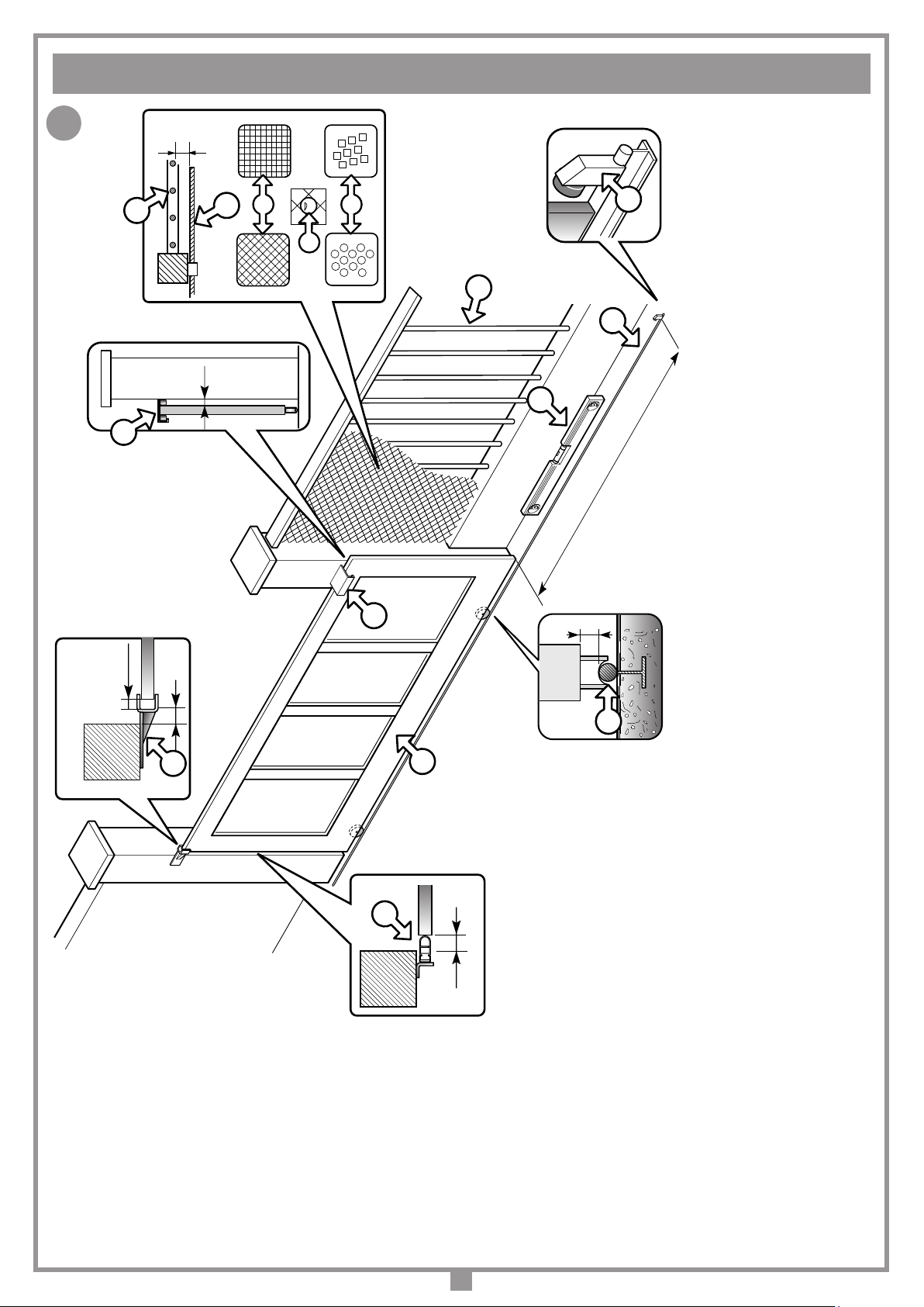
Attenzione! È assolutamente obbligatoria la presenza
delle battute antideragliamento.
Attenzione!IlmodelloreversibileSLX1024REVrichiede
una serratura elettrica per garantire il blocco dell’anta
in chiusura.
• Questo apparecchio non deve essere utilizzato da persone (bambini
compresi) con ridotte capacità siche, sensoriali o mentali, oppure mancanza
di esperienza o di conoscenza, a meno che esse abbiano potuto beneciare,
attraverso l’intermediazione di una persona responsabile della loro sicurezza,
di una sorveglianza o di istruzioni riguardanti l’utilizzo dell’apparecchio.
• Prima dell’installazione, vericare che la parte guidata sia in buone condizioni,
bilanciata correttamente e che la chiusura e l’apertura avvengano in modo
corretto.
• Evitare il rischio di intrappolamento tra la parte guidata e le parti sse
circostanti durante i movimenti di apertura e chiusura.
• Il cavo di alimentazione del motore deve essere in policloroprene conforme
alla designazione 60245 IEC 57.
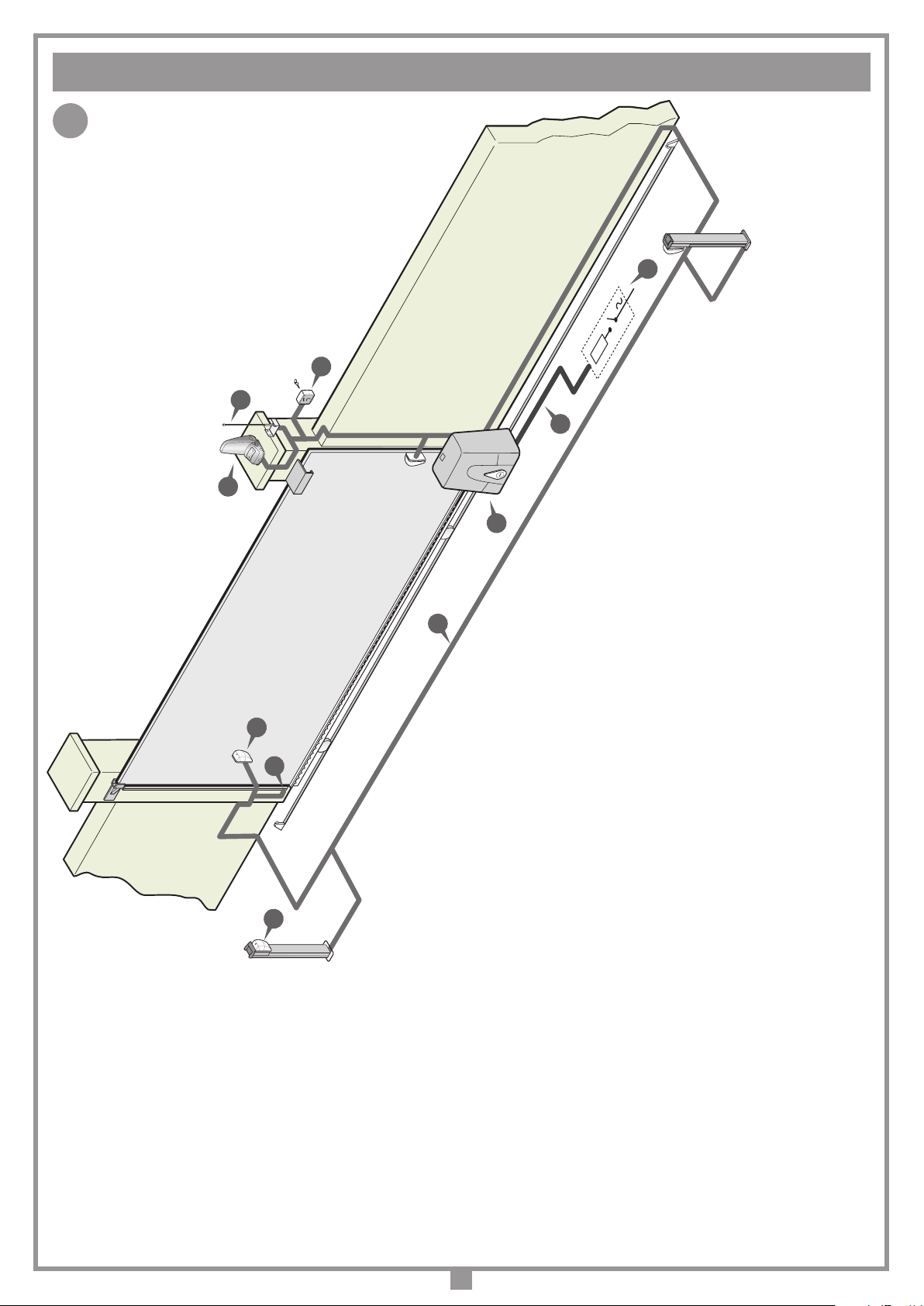
È responsabilità dell’installatore vericare le seguenti condizioni di sicurezza:
1) L’installazione deve essere sufcientemente lontana dalla strada in modo
da non costituire pericolo per la circolazione.
2) L’operatore deve essere installato all’interno della proprietà ed il cancello
non deve aprirsi verso l’area pubblica.
3) Il cancello motorizzato è principalmente adibito al passaggio di vetture e
non deve essere utilizzata con una porta pedonale.
4) I comandi (compresi quelli di emergenza) devono essere posti in vista, ad
un'altezza compresa tra 1,5 m e 1,8 m, ma non entro il raggio d’azione del
cancello. Inoltre quelli installati all’esterno devono essere protetti da una
sicurezza tale da prevenire l’uso non autorizzato.
5) Non permettere ai bambini di giocare con l'apparecchiatura o con i comandi
dell'automazione.
6) È buona norma segnalare l’automazione con targhe di
avvertenza (simili a quella in gura) che devono essere
facilmente visibili. Qualora l’automazione sia adibita al
solo passaggio di veicoli dovranno essere poste due
targhe di avvertenza di divieto di transito pedonale
(una all’interno, una all’esterno).
7) A monte dell'automazione deve essere installato un dispositivo di
sezionamento che assicuri la disconnessione onnipolare dalla rete di
alimentazione, con un a distanza di apertura dei contatti che consente la
disconnessione completa nella condizioni della sovratensione (categoria
III), conformemente alle regole di installazione nazionale.
8) La bontà della connessione di terra dell’apparecchiatura è fondamentale ai
ni della sicurezza elettrica.
9) Per qualsiasi dubbio a riguardo della sicurezza dell’installazione, non
procedere ma rivolgersi al distributore del prodotto.
Q
DESCRIZIONE TECNICA
- Alimentazione generale 230 Vac
-Motore alimentato con tensione max 37 Vdc.
- Carter superiore in materiale plastico antiurto ad alta resistenza.
- Cassadelriduttoreinalluminiopressofuso.All'internooperaunsistema
di riduzione a vite senza ne a doppia riduzione con lubricazione a
grasso uido permanente.
- Sistema di riduzione irreversibile con sblocco manuale a chiave.
- Programmatore elettronico incorporato completo di parte di potenza,
logica di controllo, carica batterie e sistema radio ricevente.
L’alimentazione viene fornita alla scheda da un trasformatore toroidale
separato, alloggiato nello stesso contenitore e collegato alla scheda
tramite Faston.
- Il sistema è dotato di controllo elettronico in frenata, riducendo al
minimo gli urti di arresto dovuti all'inerzia del cancello.
Accessori
Cremagliera in nylon rinforzato con bra di vetro, 30 mm x 20
mm, modulo 4, spezzoni lunghezza 1 m
CRENY1 4 Asole di ssaggio posto al di sotto
Per cancelli no a 600 kg
CRENY 6 Asole di ssaggio posto al di sopra
Per cancelli no a 800 kg
CREMP 6 Asole di ssaggio posto al di sotto
Per cancelli no a 800 kg
Cremagliera in acciao zincato, per il motore DRACO ed appli-
cazioni industriali no a 3000 kg.
SLOAC 22 mm x 22 mm a saldare, spezzoni di 2 m
SLOAC2 30 mm x 12 mm con asole, spezzoni di 1 m
Attenzione! Solo per clienti dell’EU - Marcatura WEEE.
Il simbolo indica che il prodotto alla ne della propria vita
utile deve essere raccolto separatamente dagli altri riuti.
L’utente dovrà pertanto conferire l’apparecchiatura agli idonei
centri di raccolta differenziata dei riuti elettronici ed elettrici,
oppure riconsegnarla al rivenditore al momento dell’acquisto
di una nuova apparecchiatura di tipo equivalente, in ragione
di uno a uno.
L’adeguata raccolta differenziata per l’avvio al riciclaggio, al trattamento
e allo smaltimento ambientalmente compatibile contribuisce ad
evitare possibili effetti negativi sull’ambiente e sulla salute e favorisce
il riciclo dei materiali. Lo smaltimento abusivo del prodotto da parte del
detentore comporta l’applicazione delle sanzioni amministrative previste
dalla normativa vigente nello Stato Comunitario di appartenenza.
Durante la manovra si deve controllare il movimento e azionare il
dispositivo di arresto immediato (STOP) in caso di pericolo.
Attenzione! Pericolo di Intrappolamento. Nell’uso del dispositivo
si consiglia di aspettare la completa apertura del cancello prima
di attraversarlo e di prestare la massima attenzione al pericolo di
intrappolamento tra cremagliera e le parti sse del installazione.
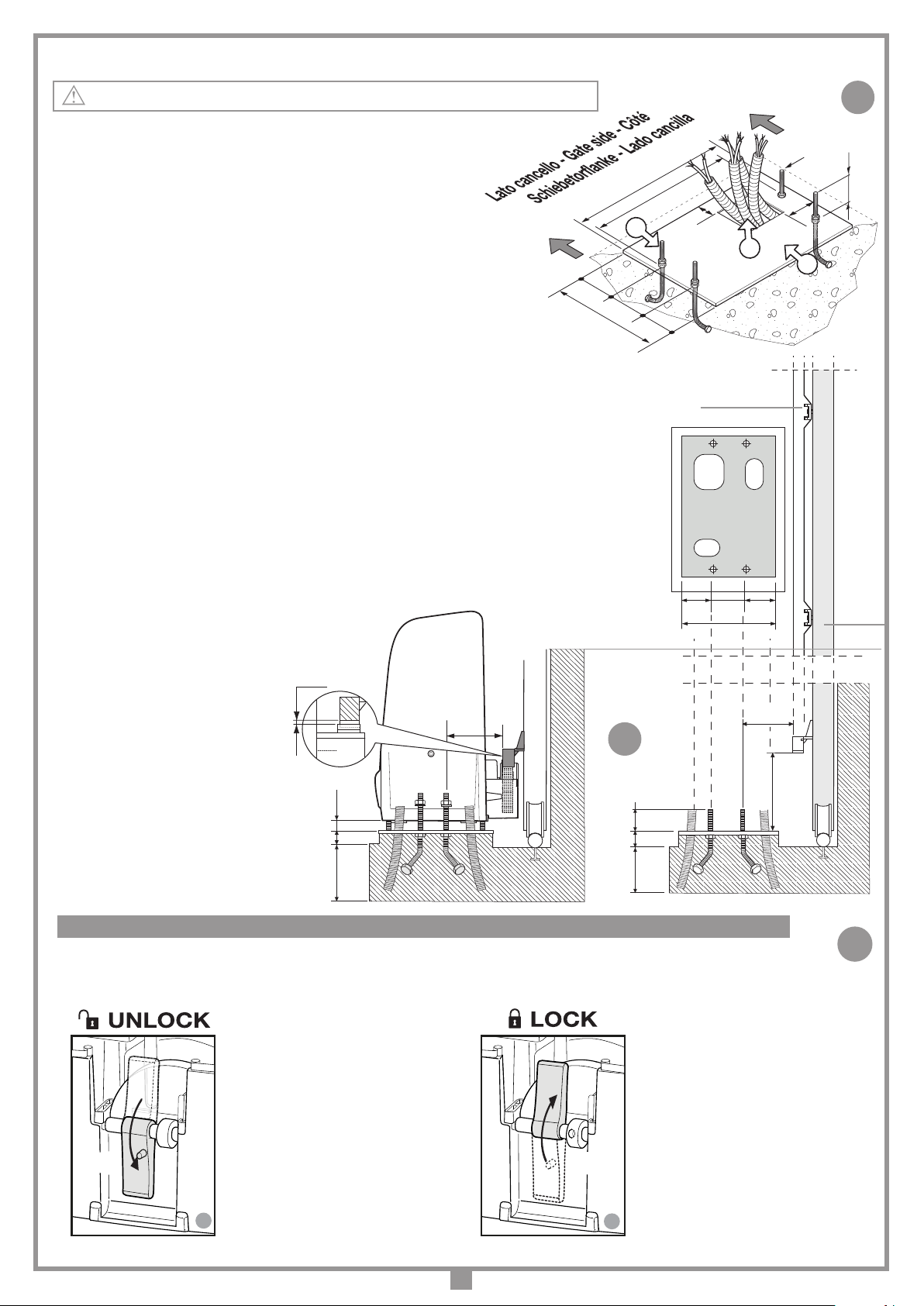
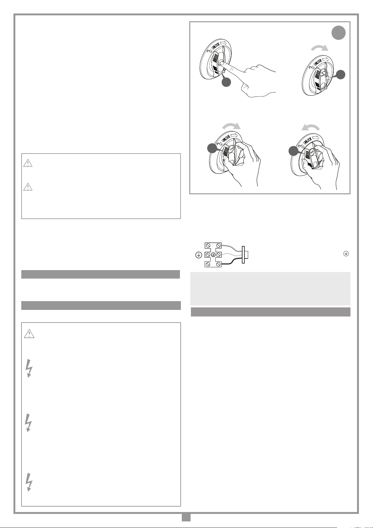
In caso di mancanza di energia elettrica e con la batteria scarica il
cancello può essere sbloccato manualmente utilizzando l'apposita chiave
di sblocco in dotazione (vedi sblocco manuale).
L'uso dell'automazione non è idoneo all'azionamento in continuo,
bensì deve essere contenuto al 70%.
ATTENZIONE! IMPORTANTI ISTRUZIONI DI SICUREZZA
CONSIDERAZIONI GENERALI DI SICUREZZA
È IMPORTANTE PER LA SICUREZZA DELLE PERSONE SEGUIRE QUESTE ISTRUZIONI: LEGGERE ATTENTAMENTE LE SEGUENTI
AVVERTENZE PRIMA DI PROCEDERE ALL’INSTALLAZIONE. PRESTARE PARTICOLARE ATTENZIONE A TUTTE LE SEGNALAZIONI
DISPOSTE NEL TESTO DI QUESTO LIBRETTO D'ISTRUZIONI ORIGINALE. IL MANCATO RISPETTO DI QUESTE POTREBBE
COMPROMETTERE IL BUON FUNZIONAMENTO DEL SISTEMA E CREARE SITUAZIONI DI PERICOLO GRAVE PER L'OPERATORE E GLI
UTILIZZATORI DEL SISTEMA STESSO. CONSERVARE QUESTE ISTRUZIONI PER OGNI FUTURO RIFERIMENTO
.
AVVERTENZE PER L'UTENTE
ZVE:572 - Mod: 04-09-2017
riello elettronica group
®
AUTOMATIC OPENING
APERTURA AUTOMATICA
FERMETURE AUTOMATISÉE
AUTOMATISCHER ÖFFNUNG
Serial number:Installation company:
Product model:
Installation date:
Weight in kg:

7
Dimensioni d'ingombro e posizionamento del gruppo
• Il motoriduttore deve essere installato rispettando il corretto posizionamento: perpendicolare al terreno, in piedi su supercie piana.
ISTRUZIONI PER L’INSTALLAZIONE
4
SCALA: 1:2
Prodotti Technocity
SL324
14-02-2005
DI0365 Description :
Product Code :
Date :
Drawing number :
P.J.Heath
CARDIN ELETTRONICA S.p.A - 31020 San Vendemiano (TV) Italy - via Raffaello, 36 Tel: 0438/401818 Fax: 0438/401831
Draft :
All rights reserved. Unauthorised copying or use of the information contained in this document is punishable by law
VISTA INTERNA CANCELLO SL1524
5
- Il motoriduttore è assemblato in fabbrica per essere instal-
lato a SINISTRA del cancello (visto dall’interno). Per l'in-
stallazione a destra impostare il parametro di installazione
motore nel libretto MULTI-ECU SOFTWARE ZVL608 fornito
con l'automazione.
Prima di procedere all'esecuzione dell'impianto vericare che la struttura
da automatizzare sia in perfetta efcienza nelle sue parti sse e mobili e
realizzata in conformità alla normativa vigente. A tal ne accertarsi che:
- la supercie dell’anta scorrevole ‘A’ sia liscia e senza sporgenze,
no all’altezza di 2,5 m dal suolo. Possono intendersi liscie anche
sporgenze dalla supercie no a 3 mm purché con bordi arrotondati.
Se la supercie dell’anta non è liscia, tutta la sua altezza, no al limite
di 2,5 m dal suolo, dovrà essere protetta con i seguenti dispositivi:
a) fotocellule
b) costa sensibile
- lo spazio ‘B’ tra parti sse e parti scorrevoli non deve essere maggiore
di 15 mm.
- la guida di scorrimento ‘C’, preferibilmente di sezione tonda, deve
essere ssata al suolo in modo stabile e indeformabile, completamente
esposta e priva di imperfezioni che possano ostacolare il movimento
del cancello;
- a cancello chiuso deve restare uno spazio libero ‘D’, per tutta l’altezza
della parte anteriore del cancello, di almeno 50 mm mentre la battuta
meccanica ‘E’ di ne corsa in chiusura deve essere posta sulla parte
superiore del cancello;
• Lo spazio libero ‘D’ può essere ricoperto da un elemento elastico
deformabile ‘F’ o meglio da una costa di sicurezza.
• Se durante il movimento di apertura, il cancello scorre vicino ad
una cancellata ‘G’ ad elementi verticali o con luci libere provvedere
all’installazione di una protezione adeguata secondo il caso:
- distanza ‘H’ maggiore di 500 mm: nessuna protezione;
- distanza ‘H’ compresa tra 500 e 300 mm: applicazione di una rete ‘I’
o di un traforato metallico ‘L’ avente aperture che non permettano il
passaggio di una sfera ‘M’ del diametro di 25 mm;
- distanza ‘H’ minore di 300 mm: applicazione di una rete ‘I’ o di un
traforato metallico ‘L’ aventi aperture che non permettano il passaggio
di una sfera ‘M’ del diametro di 12 mm. I li delle reti ‘I’ non devono
avere sezione minore di 2,5 mm2e i traforati metallici ‘L’ non devono
avere spessore minore di 1,2 mm. Oltre il limite di 2,5 m dal suolo
per il tratto ‘P’ di scorrimento del cancello tali protezioni non sono
necessarie.
• Vericare lo stato di usura di eventuali parti vecchie, consumate
del cancello e se necessario provvedere alla loro sostituzione e
lubricazione.
• Vericare la messa in bolla ‘N’ della guida.
• I pattini o rulli di guida superiori ‘O’ devono presentare un giusto gioco
allo scorrimento dell’anta e in nessun caso ostacolare la sua corsa.
• Vericare l’esistenza, assolutamente necessaria, di una battuta di
arresto ‘Q’ meccanico in apertura in corrispondenza della massima
corsa ‘P’, tale da garantire la stabilità del cancello e quindi di evitare
il pericolo di sgancio dai rulli di guida superiori ‘O’.
Attenzione! È comunque cura dell’installatore vericare i punti
critici, di pericolo, e prendere gli opportuni provvedimenti ai ni
della sicurezza e dell’incolumità personale (analisi dei rischi).
VERIFICHE PRELIMINARI (fig. 1, pag. 2)
perpendicolare
al terreno
360
330
240
65
25
5
117
165 165
SCALA: 1:2
Prodotti Technocity
SL1524SB
06-02-2002
DI0546 Description :
Product Code :
Date :
Drawing number :
P.J.Heath
CARDIN ELETTRONICA S.p.A - 31020 San Vendemiano (TV) Italy - via Raffaello, 36 Tel: 0438/401818 Fax: 0438/401831
Draft :
All rights reserved. Unauthorised copying or use of the information contained in this document is punishable by law
Dimensioni d'ingombro
SLX1524 - 1500 kg
SLX1024REV - 1000 kg
SLX824 - 800 kg
256
56
30
118
170 170
SCALA: 1:2
Prodotti Cardin
SLX324
06-02-2002
DI0546 Description :
Product Code :
Date :
Drawing number :
P.J.Heath
CARDIN ELETTRONICA S.p.A - 31020 San Vendemiano (TV) Italy - via Raffaello, 36 Tel: 0438/401818 Fax: 0438/401831
Draft :
All rights reserved. Unauthorised copying or use of the information contained in this document is punishable by law
Dimensioni d'ingombro
360
340
perpendicolare
al terreno
SLX3024 - 3000 kg
perpendicolare
al terreno
409
269
SCALA: 1:2
Prodotti CARDIN
SLXDRACO
06-10-2019
DI0964 Description :
Product Code :
Date :
Drawing number :
P.J.Heath
CARDIN ELETTRONICA S.p.A - 31020 San Vendemiano (TV) Italy - via Raffaello, 36 Tel: 0438/401818 Fax: 0438/401831
Draft :
All rights reserved. Unauthorised copying or use of the information contained in this document is punishable by law
Dimensioni d'ingombro
251
72,6
30
124
105 164
409
SLX24DRACO - 1000 kg
SLX24DRACO2 - 2000 kg

8
8
7
SCALA: 1:2
DRACO
23.04.2009
DI0966 Description :
Product Code :
Date :
Drawing number :
P.J.Heath
CARDIN ELETTRONICA S.p.A - 31020 San Vendemiano (TV) Italy - via Raffaello, 36 Tel: 0438/401818 Fax: 0438/401831
Draft :
All rights reserved. Unauthorised copying or use of the information contained in this document is punishable by law
180
Vista in pianta e di fianco senza motore
25
113
72,6
50
325
56
60
SCALA: 1:2
Prodotti Technocity
SL1524
08-02-2002
DI0240 Description :
Product Code :
Date :
Drawing number :
P.J.Heath
CARDIN ELETTRONICA S.p.A - 31020 San Vendemiano (TV) Italy - via Raffaello, 36 Tel: 0438/401818 Fax: 0438/401831
Draft :
All rights reserved. Unauthorised copying or use of the information contained in this document is punishable by law
VISTA DI FIANCO CON MOTORE
25 15
325
72,6
2 mm
ANCORAGGIO
visuale in pianta
ANCORAGGIO
visuale laterale
Ancoraggio del motoriduttore SLX24DRACO - SLX24DRACO2 (g. 6, 7)
Importante! Vericare la posizione di ancoraggio rispetto alla linea di scorrimento del cancello
• Preparare tubi e cavi di collegamento portandoli al punto d'installazione motore
(vedi g. 2).
• Avvitare le quattro zanche di ancoraggio alla piastra ‘A’ con 50 mm
sporgenti e serrare i bulloni M12.
• Preparare una piazzola di cemento con una profondità di
350 mm (25 mm sporgente per evitare che accumuli d'acqua
possano danneggiare l’apparecchiatura) nel punto esatto dove è
previsto il posizionamento del motore.
• Inserire la piastra di base avendo cura che:
- i cavi di collegamento passino attraverso il foro ‘B’;
- le zanche ‘C’ anneghino nella piazzola lasciando tutto perfettamente in bolla;
- i quattro gambi lettati sporgenti 50 mm siano perfettamente perpendicolari;
- la supercie della piastra sia pulita e senza residui di cemento.
Se la guida di scorrimento è già esistente, la piazzola di cemento deve essere ricavata
in parte anche nel getto di fondazione della guida stessa. Tale accorgimento elimina la
possibilità che le due strutture cedano in modo diverso.
• Svitare i quattro dadi M12 sui quattro gambi lettati (precedentemente utilizzati per bloccare
le zanche) dalla piastra di base.
• Posizionare il motoriduttore sui quattro gambi lettati e farlo appoggiare sulla contropiastra.
• Renderlo quindi solidale alla base utilizzando quattro rondelle e altrettanti dadi in dotazione,
curando che il gruppo rimanga in bolla e sia perfettamente stabile.
• Regolare l'altezza del gruppo utilizzando i quattro grani presenti sul motore.
Questo accorgimento permetterà tutte le regolazioni successive alla posa.
Montaggio cremagliera
• Sbloccare il motoriduttore (g. 8),
appoggiare il primo elemento di
cremagliera sul pignone e ssarlo
all'anta.
Poi spostando l'anta procedere così
con gli altri elementi di cremagliera
per tutta la lunghezza dell'anta.
• Ultimatoilssaggiodellacremagliera,
regolareilgiocopignone-cremagliera
(1-2 mm) agendo sui grani posti alla
base del motoriduttore; in modo che
il peso dell’anta non vada a gravare
sulmotoriduttore,cosachenondeve
mai succedere.
Cancello
Piastra
Cremagliera
SCALA: 1:2
Prodotti Cardin
DRACO
24-10-2019
DI0967 Description :
Product Code :
Date :
Drawing number :
P.J.Heath
CARDIN ELETTRONICA S.p.A - 31020 San Vendemiano (TV) Italy - via Raffaello, 36 Tel: 0438/401818 Fax: 0438/401831
Draft :
All rights reserved. Unauthorised copying or use of the information contained in this document is punishable by law
CONTROPIASTRA DRACO
M12
50 mm
273
64 60
180
56
36
A
C
Poortkant - Strana vrat - Grindsida
portail
255
B
23
6
L'operazione di sblocco va fatta a motore fermo. Per sbloccare l'anta del cancello munirsi della chiave in dotazione
all'apparecchiatura. Essa deve essere conservata in luogo di facile reperimento.
MANOVRA MANUALE CON MOTORE SBLOCCATO SBLOCCO A LEVA SLX24DRACO - SLX24DRACO2
2 - BLOCCO RIATTIVATO
• Ruotare la chiave in senso orario
e ruotare il copri serratura.
- sono abilitati tutti i comandi
- l’automazione riparte in modalità
‘riposizionamento’
SBLOCCO SLI
23-05-2018
DI0843 Description :
Product Code :
Date :
Drawing number :
P.J.Heath
CARDIN ELETTRONICA S.p.A - 31020 San Vendemiano (TV) Italy - via Raffaello, 36 Tel: 0438/401818 Fax: 0438/401831
Draft :
All rights reserved. Unauthorised copying or use of the information contained in this document is punishable by law
SBLOCCO MOTORE
2
1
180°
180°
1 - MOTORE SBLOCCATO
• Ruotare il copri serratura,
inserire la chiave, ruotarla di
mezzo giro in senso antiorario
- sono inibiti tutti i comandi
- il cancello può essere spostato
a mano

9
11
10
SCALA: 1:2
SL1524
23.04.2009
DI0532 Description :
Product Code :
Date :
Drawing number :
P.J.Heath
CARDIN ELETTRONICA S.p.A - 31020 San Vendemiano (TV) Italy - via Raffaello, 36 Tel: 0438/401818 Fax: 0438/401831
Draft :
All rights reserved. Unauthorised copying or use of the information contained in this document is punishable by law
6934
157
Vista in pianta e di fianco senza motore
25
110
104,5
50325
SCALA: 1:2
Prodotti Technocity
SL1524
08-02-2002
DI0240 Description :
Product Code :
Date :
Drawing number :
P.J.Heath
CARDIN ELETTRONICA S.p.A - 31020 San Vendemiano (TV) Italy - via Raffaello, 36 Tel: 0438/401818 Fax: 0438/401831
Draft :
All rights reserved. Unauthorised copying or use of the information contained in this document is punishable by law
VISTA DI FIANCO CON MOTORE
25 15
2 mm
325
ANCORAGGIO
visuale in pianta
ANCORAGGIO
visuale laterale
Ancoraggio del motoriduttore SLX3024 - SLX1524 - SLX1024REV - SLX824 (g. 9, 10)
Importante! Vericare la posizione di ancoraggio rispetto alla linea di scorrimento del cancello
• Preparare tubi e cavi di collegamento portandoli al punto d'installazione motore
(vedi g. 2).
• Avvitare le quattro zanche di ancoraggio alla piastra ‘A’ con 50 mm
sporgenti e serrare i bulloni M12.
• Preparare una piazzola di cemento con una profondità di
350 mm (25 mm sporgente per evitare che accumuli d'acqua
possano danneggiare l’apparecchiatura) nel punto esatto dove è
previsto il posizionamento del motore.
• Inserire la piastra di base avendo cura che:
- i cavi di collegamento passino attraverso il foro ‘B’;
- le zanche ‘C’ anneghino nella piazzola lasciando tutto perfettamente in bolla;
- i quattro gambi lettati sporgenti 50 mm siano perfettamente perpendicolari;
- la supercie della piastra sia pulita e senza residui di cemento.
Se la guida di scorrimento è già esistente, la piazzola di cemento deve essere ricavata
in parte anche nel getto di fondazione della guida stessa. Tale accorgimento elimina la
possibilità che le due strutture cedano in modo diverso.
• Svitare i quattro dadi M12 sui quattro gambi lettati (precedentemente utilizzati per bloccare
le zanche) dalla piastra di base.
• Posizionare il motoriduttore sui quattro gambi lettati e farlo appoggiare sulla contropiastra.
• Renderlo quindi solidale alla base utilizzando quattro rondelle e altrettanti dadi in dotazione,
curando che il gruppo rimanga in bolla e sia perfettamente stabile.
• Regolare l'altezza del gruppo utilizzando i quattro grani presenti sul motore.
Questo accorgimento permetterà tutte le regolazioni successive alla posa.
Montaggio cremagliera
• Sbloccareilmotoriduttore(g.11-12),
appoggiare il primo elemento di
cremagliera sul pignone e ssarlo
all'anta.
Poi spostando l'anta procedere così
con gli altri elementi di cremagliera
per tutta la lunghezza dell'anta.
• Ultimatoilssaggio dellacremagliera,
regolare ilgioco pignone-cremagliera
(1-2 mm) agendo sui grani posti alla
base del motoriduttore; in modo che
il peso dell’anta non vada a gravare
sul motoriduttore, cosa che non deve
mai succedere.
Cancello
Piastra
Cremagliera
SCALA: 1:2
Prodotti Technocity
SL1524M
30-01-2002
DI0237 Description :
Product Code :
Date :
Drawing number :
P.J.Heath
CARDIN ELETTRONICA S.p.A - 31020 San Vendemiano (TV) Italy - via Raffaello, 36 Tel: 0438/401818 Fax: 0438/401831
Draft :
All rights reserved. Unauthorised copying or use of the information contained in this document is punishable by law
CONTROPIASTRA SL1524M
M12
50 mm
312
31
54 34
157
69
43
A
B
C
Poortkant - Strana vrat - Grindsida
portail
279
9
L'operazione di sblocco va fatta a motore fermo. Per sbloccare l'anta del cancello munirsi della
chiave in dotazione all'apparecchiatura. Essa deve essere conservata in luogo di facile reperimento.
SBLOCCO A VITE SLX3024
Sblocco
1.Ruotare il copri serratura, inserire la chiave, ruotarla di mezzo giro in senso antiorario ed
alzare la protezione sblocco. La manopola è libera di sbloccare.
2.Ruotare la manopola in senso orario, compiendo più giri, no alla ne della sua corsa. Il riduttore
è sbloccato ed il cancello è libero di scorrere manualmente.
Attenzione! Non forzare la manopola oltre il necorsa.
Ribloccaggio
1.Ruotare la manopola in senso antiorario no a bloccarlo completamente.
2.Chiudere la protezione sblocco, ruotare la chiave in senso orario e ruotare il copri serratura.
Il riduttore è bloccato ed il cancello è pronto per l’uso.
A sistema ripristinato riporre la chiave in un luogo sicuro.
MANOVRA MANUALE CON MOTORE SBLOCCATO
SCALA: 1:2
Prodotti Technocity
SL324
07-02-2002
DI0363 Description :
Product Code :
Date :
Drawing number :
P.J.Heath
CARDIN ELETTRONICA S.p.A - 31020 San Vendemiano (TV) Italy - via Raffaello, 36 Tel: 0438/401818 Fax: 0438/401831
Draft :
All rights reserved. Unauthorised copying or use of the information contained in this document is punishable by law
Sblocco motore
A
SLX3024

10
SBLOCCO A VITE SLX1524 - SLX824
Sblocco
1.Abbassare il copri serratura ‘A’ della manopola di sblocco,
inserire la chiave ‘B’ e ruotarla di 180 gradi in senso orario.
La manopola è libera di sbloccare.
2.Ruotare la manopola ‘C’ in senso orario, compiendo più giri,
no alla ne della sua corsa. Il riduttore è sbloccato ed il can-
cello è libero di scorrere manualmente.
Attenzione! Non forzare la manopola oltre il necorsa.
Ribloccaggio
1.Ruotare la manopola ‘D’ in senso antiorario no a bloccarlo
completamente.
2.Ruotare la chiave in senso antiorario, togliere la chiave ed
alzare il copri serratura. Il riduttore è bloccato ed il cancello è
pronto per l’uso. A sistema ripristinato riporre la chiave in un
luogo sicuro.
Attenzione! Non usare lo sblocco durante il normale
funzionamento del cancello. Lo spostamento
manuale del cancello causa la perdita della
posizione da parte dell'encoder. Per ripristinare il
controllo, dopo aver ribloccato l'anta, sarà neces-
sario dare 3 o più comandi di moto afnchè l'anta,
trovando la battuta più volte, possa posizionarsi
correttamente.
Accesso al quadro di comando
Attenzione! Prima di accedere al quadro di comando
assicurarsi di aver disinserito l’interruttore generale a monte
dell’apparecchiatura.
Per accedere al motore allentare le due viti ‘A’ poste alle estremità
laterali del coperchio come indicato in gura 11.
In assenza di alimentazione il motore SLX1024REV è reversibile
e richiede una forza di spinta di almeno 35 kg per aprire l’anta.
Avvertenze importanti
• Dopo aver installato il dispositivo, e prima di dare tensione
alla centralina, vericare che il movimento del cancello
eseguito in modo manuale (con motore sbloccato) non abbia
punti di resistenza particolarmente marcata.
• La presenza del sensore di corrente non elimina l’obbligo di
installare le fotocellule o altri dispositivi di sicurezza previsti
dalle normative vigenti.
• Accertarsi, prima di eseguire il collegamento elettrico, che la
tensione e la frequenza riportate sulla targhetta caratteristiche
corrispondano a quelle dell'impianto di alimentazione.
• Il cavo di alimentazione deve essere in gomma e del tipo
60245 IEC 57 (es. 3 x 1.5 mm
2
H05RN-F).
• Lasostituzionedelcavod'alimentazionedeveessereeseguita
da personale qualicato.
• Tra la centralina di comando e la rete deve essere interposto
un interruttore onnipolare, con distanza di apertura tra i
contatti di almeno 3 mm.
• Non utilizzare cavo con conduttori in alluminio; non stagnare
l’estremità dei cavi da inserire in morsettiera; utilizzare cavo
con marcatura T min 85°C resistente agli agenti atmosferici.
• I conduttori dovranno essere adeguatamente fissati in
prossimità della morsettiera in modo che tale ssaggio serri
sia l’isolamento che il conduttore.
N
L
Fissaggio placca inferiore
06-03-95
DI0286 Description :
Product Code :
Date :
Drawing number :
P.J.Heath
CARDIN ELETTRONICA S.p.A - 31020 San Vendemiano (TV) Italy - via Raffaello, 36 Tel: 0438/401818 Fax: 0438/401831
Draft :
All rights reserved. Unauthorised copying or use of the information contained in this document is punishable by law
Collegamento motore
MANUTENZIONE
SLX1524 - SLX824
12
COLLEGAMENTO ELETTRICO
COLLEGAMENTO ALIMENTAZIONE 230 Vac
• Collegare i li di comando e quelli provenienti dalle sicurezze.
• Portare l'alimentazione generale alla morsettiera separata a
tre vie passando prima attraverso il pressacavo posizionato
in basso a destra rispetto al circuito principale:
- collegare il neutro al morsetto N
- collegare la terra al morsetto
- collegare la fase al morsetto L
Programmatore elettronica
Per la programmazione elettronica e funzionalità a batteria
consultare il libretto d'istruzioni MULTI-ECU SOFTWARE
ZVL608 fornito con l'automazione.
Per usufruire della garanzia di 36 mesi o di 50000 manovre leggere
attentamente le seguenti note.
Attenzione! Prima di eseguire qualsiasi operazione di pulizia o di
manutenzione, disinserire l'apparecchiatura dalla rete di alimenta-
zione elettrica, staccare l'alimentazione del motore e scollegare le
batterie.
Le eventuali riparazioni devono essere eseguite da personale spe-
cializzato usando materiali originali e certicati.
Il motore normalmente non necessita di particolari manutenzioni; in
ogni caso la garanzia fornita per 36 mesi o di 50000 manovre ha
validità a condizione che vengono effettuati i seguenti controlli ed
eventuali interventi sulla macchina ‘cancello scorrevole’:
- vericare la linearità della cremagliera, afnché la stessa ingrani
sempre correttamente sul pignone per tutta la sua lunghezza; in
particolare la cremagliera deve avere una sezione di 20 x 20 mm;
- vericare il gioco cremagliera - pignone (1-2 mm vedi g. 7/10);
- controllare periodicamente lo stato di usura dei perni ed eventual-
mente ingrassare le parti in moto (perni, cremagliera ecc), usando
lubricanti che mantengano uguali caratteristiche di attrito nel
tempo e adatti a funzionare tra -20 e + 70°C;
- vericare il livello di carica delle batterie;
Detteverichedevono esseredocumentateinquantosonoindispensabili
per usufruire della garanzia.
Sblocco nuovo “A”
SL1524SB
13-11-2008
DM0801 Description :
Product Code :
Date :
Drawing number :
P.J.Heath
CARDIN ELETTRONICA S.p.A - 31020 San Vendemiano (TV) Italy - via Raffaello, 36 Tel: 0438/401818 Fax: 0438/401831
Draft :
All rights reserved. Unauthorised copying or use of the information contained in this document is punishable by law
SL1524SB
A
Sblocco nuovo “B”
SL1524SB
13-11-2008
DM0802 Description :
Product Code :
Date :
Drawing number :
P.J.Heath
CARDIN ELETTRONICA S.p.A - 31020 San Vendemiano (TV) Italy - via Raffaello, 36 Tel: 0438/401818 Fax: 0438/401831
Draft :
All rights reserved. Unauthorised copying or use of the information contained in this document is punishable by law
SL1524SB
B
180°
Sblocco nuovo “C”
SL1524SB
13-11-2008
DM0803 Description :
Product Code :
Date :
Drawing number :
P.J.Heath
CARDIN ELETTRONICA S.p.A - 31020 San Vendemiano (TV) Italy - via Raffaello, 36 Tel: 0438/401818 Fax: 0438/401831
Draft :
All rights reserved. Unauthorised copying or use of the information contained in this document is punishable by law
SL1524SB
C
Sblocco nuovo “D”
SL1524SB
13-11-2008
DM0804 Description :
Product Code :
Date :
Drawing number :
P.J.Heath
CARDIN ELETTRONICA S.p.A - 31020 San Vendemiano (TV) Italy - via Raffaello, 36 Tel: 0438/401818 Fax: 0438/401831
Draft :
All rights reserved. Unauthorised copying or use of the information contained in this document is punishable by law
SL1524SB
D
5 - 6 giri 5 - 6 giri
MANOVRA MANUALE SLX1024REV

11
• These instructions are aimed at professionally qualied ‘INSTALLERS
OF ELECTRICAL EQUIPMENT’ and must respect the local standards
and regulations in force.
All materials used must be approved and must suit the environment in
which the installation is situated and all maintenance operations must
be carried out by professionally qualied technicians.
• This appliance must be used exclusively for the purpose for which it has
been made. ‘i.e. for the automation of sliding gates’ with a maximum
weight of up to
800 - 1000 - 1500 - 2000 or 3000 kg
.
Caution!The installation of both anti-derailment buffers
is absolutely obligatory.
Caution! The reversible model SLX1024REV requires
an electric lock to guarantee that the gate locks in the
closed position.
• This appliance must never be used by people (including children) with physical,
sensory or mental disabilities or by people without specic knowledge and
experience in its operation unless they are able to benet from the experience or
are being taught to use the appliance whilst being safeguarded by the presence of
somebody responsible for their safety.
• Before installing make sure that the guided parts are in good condition, correctly
balanced and that they open and close correctly.
• Avoid becoming trapped between the moving parts and the xed parts during the
opening and closing movements.
• The motor’s power cable must be made of polychloroprene in conformity with the
international standard 60245 IEC 57.
It is the responsibility of the installer to make sure that the following public safety
conditions are satised:
1) Ensure that the gate operating installation is far enough away from the main road
to eliminate possible trafc disruptions and that the size of the gate, the distance
from the road and the work cycle speed can in no way interfere, causing possible
trafc hazards.
2) The motor must be installed on the inside of the property and not on the public
side of the gate. The gates must not open onto a public area.
3) The sliding gate operator is designed for use on gates through which vehicles are
passing. The gates must not be tted with pedestrian access doors.
4) The minimum controls which may be installed are OPEN-STOP-CLOSE, these
controls must be installed at a height between 1,5 and 1,8 m and in a location
not accessible to children. Controls installed externally must be protected by a
safety device inhibiting unauthorised use.
5) Do not allow children to play with the operator or with the control devices.
6) At least two warning signs should be placed, where
they can be easily seen by the public, in the area of the
system of automatic operation. One inside the property
and one on the public side of the installation. These signs
must be indelible and not hidden by any objects (such
as tree branches, decorative fencing etc.). Make sure that the end-user is aware
that children and/or pets must not be allowed to play within the area of a gate
installation. If possible include this in the warning signs
7) Ahead of the automation a means of disconnection from the power supply must
be installed which has an opening distance on the contacts of all the poles and
ensures that the power supply is completely cut off under the conditions of a
category III overvoltage situation.
8) A correct earth connection is fundamental in order to guarantee the electrical
safety of the machine.
9) If you have any questions about the safety of the gate operating system, do
not install the operator. Contact your dealer for assistance.
TECHNICAL DESCRIPTION
- Mains power supply 230 Vac.
-Motor powered with a maximum voltage of 37 Vdc.
- Upper and lower cover in highly resistant shock-proof plastic.
- The reduction unit stator is made of die cast aluminium and contains a
never ending screw and double reduction lubricated with permanently
uid grease.
- Irreversible reduction system with a key-operated manual release
mechanism.
- The incorporated electronic programmer contains the power stage, the
logic control, battery charger and the radio receiver decoding module. The
power supply is routed to the electronics card via a separate transformer
which is housed in the same container and is connected to the card by
Faston clips.
- The system is tted with electronic deceleration control which reduces
the stress caused by the gate inertia when it stops.
Accessories
Gear rack in nylon reinforced with glass bre, 30 mm x 20 mm,
M4, 1 m pieces
CRENY1 Version with 4 lower fastening slits
For sliding gates up to 600 kg
CRENY Version with 6 upper fastening slits
For sliding gates up to 800 kg
CREMP Version with 6 lower fastening slits
For sliding gates up to 800 kg
Gearrackingalvanisedsteel for theDRACO motor and industrial
installations up to 3000 kg.
SLOAC 22 mm x 22 mm to be soldered, 2 m pieces.
SLOAC2 30 mm x 12 mm with fastening slits, 1 m pieces.
Attention!Only for EU customers - WEEE marking.
This symbol indicates that once the products life-span has
expired it must be disposed of separately from other rubbish. The
user is therefore obliged to either take the product to a suitable
differential collection site for electronic and electrical goods or
to send it back to the manufacturer if the intention is to replace
it with a new equivalent version of the same product.
Suitable differential collection, environmental friendly treatment and
disposal contributes to avoiding negative effects on the ambient and
consequently health as well as favouring the recycling of materials.
Illicitly disposing of this product by the owner is punishable by law and
will be dealt with according to the laws and standards of the individual
member nation.
During the opening/closing manoeuvre check for correct operation and
activate the emergency stop button in case of danger.
Warning! Entrapment danger. When using the device you are advised to
wait for the gate to copmpletly open before crossing its threshold and to
pay the maximum attention in order to avoid becoming trapped between the
hinged parts and the xed parts during the opening and closing movements.
During blackouts with a at battery the gate can be released and manually
manoeuvred using the supplied release key (see manual release).
The appliance is not suitable for continuous operation and may only be
operated using a duty cycle of 70%.
ATTENTION! IMPORTANT SAFETY INSTRUCTIONS
IMPORTANT SAFETY INSTRUCTIONS
READING THESE INSTRUCTIONS IS IMPORTANT FOR PERSONAL SAFETY. READ THE FOLLOWING
REMARKS CAREFULLY BEFORE PROCEEDING WITH THE INSTALLATION. PAY PARTICULAR ATTENTION TO
ALL THE PARAGRAPHS MARKED WITH THE SYMBOL IN THIS ORIGINAL INSTRUCTION MANUAL. NOT
READING THESE IMPORTANT INSTRUCTIONS COULD COMPROMISE THE CORRECT WORKING ORDER OF THE SYSTEM
AND CREATE DANGER SITUATIONS FOR THE USERS OF THE SYSTEM. SAVE THESE INSTRUCTIONS FOR FUTURE USE.
USER INSTRUCTIONS
ZVE:572 - Mod: 04-09-2017
riello elettronica group
®
AUTOMATIC OPENING
APERTURA AUTOMATICA
FERMETURE AUTOMATISÉE
AUTOMATISCHER ÖFFNUNG
Serial number:Installation company:
Product model:
Installation date:
Weight in kg:
Q

12
Overall dimensions and positioning
• The geared motor must be correctly positioned when it is installed: perpendicular to the ground and straight up on at ground.
INSTALLATION INSTRUCTIONS
4
SCALA: 1:2
Prodotti Technocity
SL324
14-02-2005
DI0365 Description :
Product Code :
Date :
Drawing number :
P.J.Heath
CARDIN ELETTRONICA S.p.A - 31020 San Vendemiano (TV) Italy - via Raffaello, 36 Tel: 0438/401818 Fax: 0438/401831
Draft :
All rights reserved. Unauthorised copying or use of the information contained in this document is punishable by law
VISTA INTERNA CANCELLO SL1524
5
perpendicular
to the ground
- The geared motor unit has been assembled in the factory
to be tted to the LEFT SIDE of the gate (internal view).
To install the motor to the right set the installation parameter
in the instruction manual MULTI-ECU SOFTWARE ZVL608
supplied with the automation.
Before starting the installation make sure that the structure which
is to be automated is in good working order and respects the local
standards and regulations in force.
To this end ensure that:
- the surface of the sliding gate “A” is smooth and has no
protrusions up to a distance of 2,5 m from ground level.
Protrusions on the gate surface which are not greater than 3
mm and have rounded edges are acceptable.
If the surface of the gate is not smooth, the entire height up to
2,5 m from the ground must be protected by two of the following
devices:
a) photoelectric cells
b) contact safety buffer;
- the distance ‘B’ between the xed parts and sliding parts of the
installation must not exceed 15 mm;
- the runner guide ‘C’, preferably round, should be securely xed
to the ground, completely exposed and free of any imperfections
which could inhibit the correct movement of the gate;
- when the gate is closed a space of 50 mm ‘D’ must remain for
the entire height of the front part of the gate and a mechanical
travel limit ‘E’ must be positioned on the upper part of the gate.
• The free space ‘D’ can be covered with a rubber anti-crush buffer
‘F’ or better still a pneumatic or photoelectric contact safety
buffer.
• If the gate slides past a xed structure ‘G’ which has railings or
bars leaving open spaces, it must be protected in one of the
following ways:
- distance ‘H’ greater than 500 mm: no protection required;
- distance ‘H’ between 500 and 300 mm: wire mesh fencing ‘I’ or
punched metal plating ‘L’ with an opening which does not allow
the passage of a 25 mm diameter sphere ‘M’ must be tted;
- distance ‘H’ smaller than 300 mm: wire mesh fencing ‘I’ or
punched metal plating ‘L’ with an opening which does not allow
the passage of a 12 mm diameter sphere ‘M’ must be tted.
The wires of the mesh ‘I’ must not have a cross-section of less
than 2,5 mm
2
and the punched metal plating ‘L’ must not have
a thickness of less than 1.2 mm. Protection is not necessary for
the area ‘P’ if the xed structure with railings or bars is over 2,5
mabove the ground.
• Check the gate components, replace any worn or damaged
parts and then lubricate them.
• Using a spirit level ‘N’ check that the castor guide is in square.
• The upper runner guide ‘O’ must have the correct play for the
gate and must not inhibit the gate’s sliding action.
• Check that a mechanical travel limit ‘Q’ (absolutely necessary)
has been tted in the opening direction and that it corresponds
to the maximum travel distance ‘P’ of the gate. The travel limit
must guarantee anti-derailment and gate stability.
Warning! It is the installer’s responsibility to check all
critical danger points, to take action and to install any
devices needed to guarantee the safety of all people
using the gate (risk analysis).
PRELIMINARY CHECKS (fig. 1, pag. 2)
perpendicular
to the ground
360
330
240
65
25
5
117
165 165
SCALA: 1:2
Prodotti Technocity
SL1524SB
06-02-2002
DI0546 Description :
Product Code :
Date :
Drawing number :
P.J.Heath
CARDIN ELETTRONICA S.p.A - 31020 San Vendemiano (TV) Italy - via Raffaello, 36 Tel: 0438/401818 Fax: 0438/401831
Draft :
All rights reserved. Unauthorised copying or use of the information contained in this document is punishable by law
Dimensioni d'ingombro
SLX1524 - 1500 kg
SLX1024REV - 1000 kg
SLX824 - 800 kg
256
56
30
118
170 170
SCALA: 1:2
Prodotti Cardin
SLX324
06-02-2002
DI0546 Description :
Product Code :
Date :
Drawing number :
P.J.Heath
CARDIN ELETTRONICA S.p.A - 31020 San Vendemiano (TV) Italy - via Raffaello, 36 Tel: 0438/401818 Fax: 0438/401831
Draft :
All rights reserved. Unauthorised copying or use of the information contained in this document is punishable by law
Dimensioni d'ingombro
360
340
perpendicular
to the ground
SLX3024 - 3000 kg
409
269
SCALA: 1:2
Prodotti CARDIN
SLXDRACO
06-10-2019
DI0964 Description :
Product Code :
Date :
Drawing number :
P.J.Heath
CARDIN ELETTRONICA S.p.A - 31020 San Vendemiano (TV) Italy - via Raffaello, 36 Tel: 0438/401818 Fax: 0438/401831
Draft :
All rights reserved. Unauthorised copying or use of the information contained in this document is punishable by law
Dimensioni d'ingombro
251
72,6
30
124
105 164
409
SLX24DRACO - 1000 kg
SLX24DRACO2 - 2000 kg

13
8
7
SCALA: 1:2
DRACO
23.04.2009
DI0966 Description :
Product Code :
Date :
Drawing number :
P.J.Heath
CARDIN ELETTRONICA S.p.A - 31020 San Vendemiano (TV) Italy - via Raffaello, 36 Tel: 0438/401818 Fax: 0438/401831
Draft :
All rights reserved. Unauthorised copying or use of the information contained in this document is punishable by law
180
Vista in pianta e di fianco senza motore
25
113
72,6
50
325
56
60
SCALA: 1:2
Prodotti Technocity
SL1524
08-02-2002
DI0240 Description :
Product Code :
Date :
Drawing number :
P.J.Heath
CARDIN ELETTRONICA S.p.A - 31020 San Vendemiano (TV) Italy - via Raffaello, 36 Tel: 0438/401818 Fax: 0438/401831
Draft :
All rights reserved. Unauthorised copying or use of the information contained in this document is punishable by law
VISTA DI FIANCO CON MOTORE
25 15
325
72,6
2 mm
Anchoring the unit
SLX24DRACO
- SLX24DRACO2 (g. 6, 7)
Important! Check the exact anchoring position with respect to the alignment of the sliding gate
• Run the piping and connection wires to the position where the motor is to be
installed.
• Attach the anchor bolts to the base plate ‘A’ allowing them to protrude
by 50 mm and then tighten down using the supplied M12 nuts.
• Prepare a cement plinth, in the position where the motor is to
be installed, with a depth of 350 mm (the base should protrude
by about 25 mm to avoid damage by pools of water building up
under the appliance).
• Insert the base plate making sure that:
- the electrical cables pass through the hole ‘B’;
- the anchor bolts ‘C’ are immersed into the cement base and the base plate
is perfectly level;
- the four protruding threaded bolts are perpendicular to the base plate;
- the surface area of the base plate is clean and free of cement residue.
If the runner guide already exists the cement base should be extended to take in part of
the runner guide foundation. This will stop the two foundations from giving way separately.
- Unscrew the four M12 nuts on the four threaded bolts (previously used to block the anchor
bolts) from the base of the anchor plate. Then insert the four washers and allow them to rest
on the nuts.
- Position the geared motor over the four threaded bolts and allow it to rest on the four washers.
- Fasten in to the base using the other four washers and
adjustment nuts supplied with the kit, making sure that the unit remains perfectly level and
stable.
- Adjust the height if the unit using the four grub screws already positioned on the motor. This
will allow you to adjust the height
and position of the motor later on.
Fitting the gear rack
- release the geared motor (g. 8), lay
the rst stretch of the toothed rack
on the pinion and x it to the gate,
then fasten down all the other parts
along the entire length of the gate.
- after having fastened the toothed
rack, realign the pinion (play of 1 to
2 mm between the gear runner and
the pinion) using the grub screws at
the base of the geared motor. This
action will prevent the weight of the
sliding gate from damaging the unit
when working.
SCALA: 1:2
Prodotti Cardin
DRACO
24-10-2019
DI0967 Description :
Product Code :
Date :
Drawing number :
P.J.Heath
CARDIN ELETTRONICA S.p.A - 31020 San Vendemiano (TV) Italy - via Raffaello, 36 Tel: 0438/401818 Fax: 0438/401831
Draft :
All rights reserved. Unauthorised copying or use of the information contained in this document is punishable by law
CONTROPIASTRA DRACO
M12
50 mm
273
64 60
180
56
36
A
C
Poortkant - Strana vrat - Grindsida
portail
255
B
23
6
Manual release is to be carried out with the motor stopped. To release the gate use the manual release key supplied with
the unit. The key should be kept in an easily accessible place.
LEVER ACTIVATED MANUAL MANOEUVRE WITH THE MOTOR RELEASED SLX24DRACO - SLX24DRACO2
2- RELEASE MEC. REACTIVATED
• Rotate the knob anticlockwise
and replace the lock protection
disk.
- all commands are enabled
- the automation will start up
again in the repositioning mode.
SBLOCCO SLI
23-05-2018
DI0843 Description :
Product Code :
Date :
Drawing number :
P.J.Heath
CARDIN ELETTRONICA S.p.A - 31020 San Vendemiano (TV) Italy - via Raffaello, 36 Tel: 0438/401818 Fax: 0438/401831
Draft :
All rights reserved. Unauthorised copying or use of the information contained in this document is punishable by law
SBLOCCO MOTORE
2
1
180°
180°
1 - MOTOR RELEASED
• Rotate the lock protection
disk, insert the key, rotate it
half a turn anticlockwise
- all commands are inhibited
- the gate can be moved by
hand
ANCHORING
THE UNIT
Plan view
ANCHORING
THE UNIT
Side view
Gate
Base plate
Gear rack

14
11
10
SCALA: 1:2
SL1524
23.04.2009
DI0532 Description :
Product Code :
Date :
Drawing number :
P.J.Heath
CARDIN ELETTRONICA S.p.A - 31020 San Vendemiano (TV) Italy - via Raffaello, 36 Tel: 0438/401818 Fax: 0438/401831
Draft :
All rights reserved. Unauthorised copying or use of the information contained in this document is punishable by law
6934
157
Vista in pianta e di fianco senza motore
25
110
104,5
50325
SCALA: 1:2
Prodotti Technocity
SL1524
08-02-2002
DI0240 Description :
Product Code :
Date :
Drawing number :
P.J.Heath
CARDIN ELETTRONICA S.p.A - 31020 San Vendemiano (TV) Italy - via Raffaello, 36 Tel: 0438/401818 Fax: 0438/401831
Draft :
All rights reserved. Unauthorised copying or use of the information contained in this document is punishable by law
VISTA DI FIANCO CON MOTORE
25 15
2 mm
325
ANCHORING
THE UNIT
Plan view
ANCHORING
THE UNIT
Side view
Anchoring the unit
SLX3024 - SLX1524 - SLX1024REV - SLX824 (g. 9, 10)
Important! Check the exact anchoring position with respect to the alignment of the sliding gate
• Run the piping and connection wires to the position where the motor is to be
installed.
• Attach the anchor bolts to the base plate ‘A’ allowing them to protrude
by 50 mm and then tighten down using the supplied M12 nuts.
• Prepare a cement plinth, in the position where the motor is to
be installed, with a depth of 350 mm (the base should protrude
by about 25 mm to avoid damage by pools of water building up
under the appliance).
• Insert the base plate making sure that:
- the electrical cables pass through the hole ‘B’;
- the anchor bolts ‘C’ are immersed into the cement base and the base plate
is perfectly level;
- the four protruding threaded bolts are perpendicular to the base plate;
- the surface area of the base plate is clean and free of cement residue.
If the runner guide already exists the cement base should be extended to take in part of the
runner guide foundation. This will stop the two foundations from giving way separately.
- Unscrew the four M12 nuts on the four threaded bolts (previously used to block the anchor
bolts) from the base of the anchor plate. Then insert the four washers and allow them to rest on
the nuts.
- Position the geared motor over the four threaded bolts and allow it to rest on the four washers.
- Fasten in to the base using the other four washers and
adjustment nuts supplied with the kit, making sure that the unit remains perfectly level and stable.
- Adjust the height if the unit using the four grub screws already positioned on the motor. This will
allow you to adjust the height and position of the motor later on.
Fitting the gear rack
- release the geared motor (g.
11-12), lay the rst stretch of the
toothed rack on the pinion and x
it to the gate, then fasten down all
the other parts along the entire
length of the gate.
- after having fastened the toothed
rack, realign the pinion (play of 1
to 2 mm between the gear runner
and the pinion) using the grub
screws at the base of the geared
motor. This action will prevent the
weight of the sliding gate from
damaging the unit when working.
Gate
Base plate
Gear rack
SCALA: 1:2
Prodotti Technocity
SL1524M
30-01-2002
DI0237 Description :
Product Code :
Date :
Drawing number :
P.J.Heath
CARDIN ELETTRONICA S.p.A - 31020 San Vendemiano (TV) Italy - via Raffaello, 36 Tel: 0438/401818 Fax: 0438/401831
Draft :
All rights reserved. Unauthorised copying or use of the information contained in this document is punishable by law
CONTROPIASTRA SL1524M
M12
50 mm
312
31
54 34
157
69
43
A
B
C
Poortkant - Strana vrat - Grindsida
portail
279
9
Manual release is to be carried out with the motor stopped. To release the gate use the manual
release key supplied with the unit. The key should be kept in an easily accessible place.
SCREW OPERATED MANUAL RELEASE SYSTEM SLX3024
To release the unit
1.Rotate the lock protection disk, insert the key, rotate it half a turn anticlockwise and lift up
the knob cover.
The knob is now free and can be released.
2.Rotate the knob clockwise until it can turn no more.
Attention: do not force the knob to turn further than its travel limit.
The gears are now released and the gate can be moved manually.
To relock the unit
1.Rotate the knob anticlockwise and move it back to the blocked position.
2.Close the knob cover, rotate the key clockwise and rotate the lock protection disk cover.
The gears are now blocked and the gate is ready for use.
Once the system has been reset store the key in a safe place.
MANUAL MANOEUVRE WITH THE MOTOR RELEASED
SCALA: 1:2
Prodotti Technocity
SL324
07-02-2002
DI0363 Description :
Product Code :
Date :
Drawing number :
P.J.Heath
CARDIN ELETTRONICA S.p.A - 31020 San Vendemiano (TV) Italy - via Raffaello, 36 Tel: 0438/401818 Fax: 0438/401831
Draft :
All rights reserved. Unauthorised copying or use of the information contained in this document is punishable by law
Sblocco motore
A
SLX3024

15
MAINS POWER SUPPLY CONNECTION 230 Vac
• Connect the control and security device wires.
• Runthemainspowersupplythroughthecableclamplocatedon
the bottom right of the main circuit board and to the separate
3-way terminal board:
- connect the neutral to binding post N
- connect the earth to binding post
- connect the live to binding post L
Electronic programming unit
Instructions for programming the ECU and battery powered
operationcan befound inthe MULTI-ECU SOFTWAREmanual
ZVL608 supplied with the automation
.
To use the 36 month or 50000 manoeuvre guarantee, read the
following notes carefully.
Attention! Before carrying out any cleaning or maintenance
operations make sure the power is disconnected at the mains,
the motor power cables are disconnected and the batteries
have been disconnected.
Eventual repair work must be carried out by specialised per-
sonnel using original spare parts.
The motor does not normally require particular maintenance; in
any case the 36 month or 50000 manoeuvre guarantee is only
valid if the following controls have been observed and eventual
maintenance has been carried out to the machine ‘sliding gate’:
- check the straightness of the toothed rack, make sure the teeth
t correctly in the pinion throughout its entire length; in particular
the gear rack must have a cross section of 20 x 20 mm;
- check the play of the gear rack - pinion (1-2 mm see g. 7/10);
- periodically check the moving parts for wear and tear and
grease if required, using lubricants which maintain their friction
levels unaltered throughout time and are suitable for temper-
atures of -20 to +70°C;
- check the battery charge level.
These checks must be written down as they are paramount in
validating the guarantee.
SCREW OPERATED MANUAL RELEASE SYSTEM
SLX1524 - SLX824
To release the unit
1. Lower the lock protection ‘A’ on the release knob, insert the
key ‘B’ and rotate it through 180 degrees clockwise. The knob
is now free and can be rotated.
2. Rotate the knob ‘C’ clockwise until reaches its travel limit.
The geared motor is now released and the gate can be moved
manually.
Attention! Do not force the knob to exceed the travel limit.
To relock the unit
1. Rotate the knob ‘D’ anticlockwise until it blocks completely.
2. Rotate the key anticlockwise and position the lock protection.
The geared motor is now locked and the gate may be used
normally.
Once the system has been reset store the key in a safe place.
Attention! Never use the manual release mechanism
while the gate is in operation.
Moving the gate manually will force the encoder to
lose the position of the gate. To reset the control, once
the gate has been relocked, you will need to give 3
or more movement commands so that the gate leaf
will reach the travel limit enough times to position
itself correctly.
Access to the electronic card
Attention! Before opening the cover make sure that the power
has been switched off at the mains. To access the motor loosen
the two screws ‘A’ positioned on either end of the cover as
indicated in gure 11.
Attention! When the power is off the SLX1024REV motor is
reversible and requires a force of at least 35 kg to open the gate.
Important remarks
• After having installed the device, and before powering
up the programmer, release the door (manual release
mechanism) and move it manually, checking that it moves
smoothly and has no unusual points of resistance.
• The presence of the electrical current sensor does not
dispense with the obligation to install photoelectric cells
and other safety devices foreseen by the safety standards
in force.
• Beforeconnecting the appliance make surethatthevoltage
and frequency rated on the data plate conform to those of
the mains supply.
• The motor’s power cable must be made of polychloroprene
in conformity with the international standard 60245 IEC 57
(e.g. 3 x 1.5 mm
2
H05RN-F).
• The cable may only be replaced by qualied technicians.
• An all pole trip switch with at least 3 mm between the
contacts must be installed between the unit and the mains
supply.
• Don’t use cables with aluminium conductors; don’t solder
the ends of cables which are to be inserted into the binding
posts; use cables marked T min 85°C and resistant to
atmospheric agents.
• The terminal wires must be positioned in such a way that
both the wire and the insulating sheath are tightly fastened.
N
L
Fissaggio placca inferiore
06-03-95
DI0286 Description :
Product Code :
Date :
Drawing number :
P.J.Heath
CARDIN ELETTRONICA S.p.A - 31020 San Vendemiano (TV) Italy - via Raffaello, 36 Tel: 0438/401818 Fax: 0438/401831
Draft :
All rights reserved. Unauthorised copying or use of the information contained in this document is punishable by law
Collegamento motore
MAINTENANCE
12
ELECTRICAL CONNECTION
Sblocco nuovo “A”
SL1524SB
13-11-2008
DM0801 Description :
Product Code :
Date :
Drawing number :
P.J.Heath
CARDIN ELETTRONICA S.p.A - 31020 San Vendemiano (TV) Italy - via Raffaello, 36 Tel: 0438/401818 Fax: 0438/401831
Draft :
All rights reserved. Unauthorised copying or use of the information contained in this document is punishable by law
SL1524SB
A
Sblocco nuovo “B”
SL1524SB
13-11-2008
DM0802 Description :
Product Code :
Date :
Drawing number :
P.J.Heath
CARDIN ELETTRONICA S.p.A - 31020 San Vendemiano (TV) Italy - via Raffaello, 36 Tel: 0438/401818 Fax: 0438/401831
Draft :
All rights reserved. Unauthorised copying or use of the information contained in this document is punishable by law
SL1524SB
B
180°
Sblocco nuovo “C”
SL1524SB
13-11-2008
DM0803 Description :
Product Code :
Date :
Drawing number :
P.J.Heath
CARDIN ELETTRONICA S.p.A - 31020 San Vendemiano (TV) Italy - via Raffaello, 36 Tel: 0438/401818 Fax: 0438/401831
Draft :
All rights reserved. Unauthorised copying or use of the information contained in this document is punishable by law
SL1524SB
C
Sblocco nuovo “D”
SL1524SB
13-11-2008
DM0804 Description :
Product Code :
Date :
Drawing number :
P.J.Heath
CARDIN ELETTRONICA S.p.A - 31020 San Vendemiano (TV) Italy - via Raffaello, 36 Tel: 0438/401818 Fax: 0438/401831
Draft :
All rights reserved. Unauthorised copying or use of the information contained in this document is punishable by law
SL1524SB
D
5 - 6 turns 5 - 6 turns
SLX1524 - SLX824
OPENING THE GATE BY HAND SLX1024REV

16
• Celivretestdestinéàdespersonnestitulairesd’uncerticatd’aptitude
professionnelle pour l’installation des ‘appareils électriques’
et requiert une bonne connaissance de la technique appliquée
professionnellement, ainsi que des normes en vigueur.
Lesmatérielsutilisésdoiventêtrecertiésetêtreadaptésauxconditions
atmosphériques du lieu d’implantation. Les travaux de maintenance
doivent être effectués par un personnel qualié.
• Les appareils décrits dans ce livret ne doivent être destinés qu’à
l’utilisation pour laquelle ils ont été expressément conçus, à savoir:
‘La motorisation de portails coulissants d’un poids jusqu’à
800 -
1000 - 1500 - 2000 et 3000 kg
’.
Attention!Il est absolument indispensable que les
butées anti-déraillement soient installées.
Attention!Le modèle réversible SLX1024REV
nécessite une serrure électrique pour garantir le
verrouillage du vantail en fermeture.
• Cet appareil ne doit pas être utilisé par des personnes (y compris des
enfants) aux capacités physiques, sensorielles ou mentales réduites
ou ne possédant pas l’expérience et les connaissances nécessaires à
moins qu’elles n’aient reçu des instructions spéciques ou bénécient
de la surveillance d’une personne responsable de leur sécurité pour
l’utilisation de l’appareil.
• Avant de procéder à l’installation, contrôler que la partie entraînée soit
en bon état, qu’elle soit parfaitement équilibrée et que la fermeture et
l’ouverture s’effectuent correctement.
• Éviter le risque de rester coincer entre la partie entraînée et les parties
xes pendant les manœuvres d’ouverture et fermeture.
• Le câble d’alimentation du moteur doit être en polychloroprène conforme
à la désignation 60245 IEC 57.
Il appartient à l’installateur de vérier les conditions de sécurité ci-dessous:
1) L’installation doit se trouver sufsamment loin de la route pour ne pas
constituer de risque pour la circulation.
2) Le moteur doit être installé à l’intérieur de la propriété et le portail ne doit
pas s’ouvrir sur le domaine public.
3) Le portail motorisé est affecté principalement au passage de véhicules
et ne doit pas être utilisé comme porte piétons
4) Les organes de commande (y compris les boutons d’arrêt d’urgence)
doivent être placés de façon qu’ils soient bien en vue, à une hauteur
oscillant entre 1,5 met 1,8 met hors durayon d’action duportail. En outre,
ceux placés à l’extérieur doivent être protégés de manière à empêcher
toute utilisation non autorisée.
5) Nepas permettreaux enfantsdejoueravecl’appareilouavecsesorganes
de commande.
6) Il est conseillé de signaler l’automatisation du
portail par des panneaux de signalisation (comme
celui indiqué en gure) placés bien en vue. Dans
l’hypothèse où l’automatisme serait affecté
exclusivement au passage de véhicules, il faudra
prévoir deux panneaux d’interdiction de passage aux piétons (l’un à
l’intérieur et l’autre à l’extérieur).
7) Il est impératif de poser, en amont de l’automatisme, un disjoncteur qui
garantit une déconnexion omnipolaire de la ligne d’alimentation. Ce
dispositif doit avoir une ouverture des contacts telle à permettre une
déconnexioncomplèteencasdesurtension(catégorieIII),conformément
aux règles d’installation nationales.
8) Pour garantir la sécurité électrique, il est impératif de brancher l’appareil
à la prise de terre.
9) Encas d’un quelconquedoute sur lasécurité de l’installation,interrompre
la pose et contacter le distributeur du matériel.
DESCRIPTION TECHNIQUE
Alimentation générale 230 Vac
- Tension d’alimentation du moteur: 37 Vdc maximum.
- Capot de protection en matière plastique antichoc haute résistance.
- Caisson du réducteur en aluminium moulé sous pression.
Dans ce caisson opère un système de réduction à vis sans n à double
réduction, lubrication permanente par graisse uide.
- Système de réduction irréversible avec déverrouillage manuel par clé.
- Programmateur électronique intégré, doté d’une partie de puissance,
logique de contrôle, chargeur de batterie et système radio récepteur.
L’alimentation est fournie à la carte par l’intermédiaire d’un
transformateur toroïdal séparé, logé dans le même boîtier et branché
à la carte par cosses Faston.
- Lesystèmeestdotéd’undispositifdecontrôleélectroniqueenfreinage,
ce qui permet de réduire au maximum les chocs d’arrêt dus à l’inertie
du portail.
Accessoires
Crémaillère en nylon armé en bre de verre, 30 mm x 20 mm, module
4, tronçons de 1 m
CRENY1 4 trous oblongs de xation, situés en partie basse.
Pour portails jusqu’à 600 kg.
CRENY 6 trous oblongs de xation, situés en partie haute.
Pour portails jusqu’à 800 kg.
CREMP 6 trous oblongs de xation, situés en partie basse.
Pour portails jusqu’à 800 kg.
Crémaillèreenaciergalvanisé,pourlemoteurDRACOetapplications
industrielles jusqu’à 3000 kg.
SLOAC 22 mm x 22 mm à souder, tronçons de 2 m
SLOAC2 30 mm x 12 mm avec trous oblongs, tronçons de 1 m
Attention! Seulement pour les clients de l’UE - Marquage WEEE.
Ce symbole indique l’obligation de ne pas éliminer l’appareil, à la n de
sa durée de vie, avec les déchets municipaux non triés et de procéder
à sa collecte sélective. Par conséquent, l’utilisateur doit remettre
l’appareil à un centre de collecte sélective des déchets électroniques
et électriques ou au revendeur qui est tenu, lorsqu’il fournit un nouvel
appareil, de faire en sorte que les déchets puissent lui être remis,
sur une base de un pour un, pour autant que l’appareil soit de type
équivalent à celui qu’il fournit.
La collecte sélective des équipements électriques et électroniques en vue de leur
valorisation, leur traitement et leur élimination dans le respect de l’environnement
contribue à éviter la nocivité desdits équipements pour l’environnement et pour
la santé et à encourager leur recyclage. L’élimination abusive de l’équipement de
la part du détenteur nal comporte l’application des sanctions administratives
prévues par les normes en vigueur dans l’État Membre d’appartenance.
Durant la manœuvre, contrôler le mouvement et actionner, en cas de
danger, le dispositif d’arrêt d’urgence (STOP).
Attention! Risque de coincement. Pendant l’utilisation de l’appareil,
nousconseillonsd’attendrequeleportail soitcomplètementouvert avant
de le franchir et de prêter une grande attention au risque de coincement
qui existe entre la crémaillère et les parties xes de l’installation. En
cas de coupure de courant et batterie déchargée, le portail peut être
déverrouillé manuellement au moyen de la clé de déverrouillage fournie
en dotation (voir ‘Déverrouillage manuel’).
L’automatismen’estpasadaptéàuneactivationcontinue;l’actionnement
doit se limiter à 70%.
ATTENTION! CONSIGNES DE SÉCURITÉ IMPORTANTES
CONSIGNES GÉNÉRALES DE SÉCURITÉ
IL EST IMPORTANT POUR LA SÉCURITÉ DES PERSONES D’OBSERVER LES INSTRUCTIONS SUIVANTES: LIRE ATTENTIVEMENT
LES CONSIGNES SUIVANTES AVANT DE PROCÉDER AU MONTAGE. PORTER UNE ATTENTION PARTICULIÈRE À TOUTES LES
CONSIGNES MISES EN ÉVIDENCE PAR LES PICTOGRAMMES FIGURANT DANS LE PRÉSENT LIVRET D’INSTRUCTIONS
ORIGINAL. LE NON-RESPECT DE CES CONSIGNES POURRAIT COMPROMETTRE LE BON FONCTIONNEMENT DU
SYSTÈME ET CRÉER DES SITUATIONS DE GRAVE DANGER POUR L’OPÉRATEUR ET LES UTILISATEURS DU SYSTÈME.
CONSERVER CETTE NOTICE POUR POUVOIR LA CONSULTER ULTÉRIEUREMENT.
CONSIGNES POUR L’UTILISATEUR
ZVE:572 - Mod: 04-09-2017
riello elettronica group
®
AUTOMATIC OPENING
APERTURA AUTOMATICA
FERMETURE AUTOMATISÉE
AUTOMATISCHER ÖFFNUNG
Serial number:Installation company:
Product model:
Installation date:
Weight in kg:
Q

17
360
330
240
65
25
5
117
165 165
SCALA: 1:2
Prodotti Technocity
SL1524SB
06-02-2002
DI0546 Description :
Product Code :
Date :
Drawing number :
P.J.Heath
CARDIN ELETTRONICA S.p.A - 31020 San Vendemiano (TV) Italy - via Raffaello, 36 Tel: 0438/401818 Fax: 0438/401831
Draft :
All rights reserved. Unauthorised copying or use of the information contained in this document is punishable by law
Dimensioni d'ingombro
Dimensions d’encombrement et instructions sur l’implantation du groupe
• Le motoréducteur doit être monté en veillant à respecter la bonne position, c’est-à-dire perpendiculaire au sol, debout sur surface plane.
INSTRUCTIONS POUR L’INSTALLATION
4
SCALA: 1:2
Prodotti Technocity
SL324
14-02-2005
DI0365 Description :
Product Code :
Date :
Drawing number :
P.J.Heath
CARDIN ELETTRONICA S.p.A - 31020 San Vendemiano (TV) Italy - via Raffaello, 36 Tel: 0438/401818 Fax: 0438/401831
Draft :
All rights reserved. Unauthorised copying or use of the information contained in this document is punishable by law
VISTA INTERNA CANCELLO SL1524
5
perpendiculaire
au sol
- Le motoréducteur est assemblé à l’usine pour être
installé à gauche du portail (vu de l’intérieur). Pour
l’installer à droite, régler le paramètre Montage Moteur
dans la notice d’installation logiciel MULTI-ECU ZVL608
fourni avec l’automatisme.
Avant la pose, vérier que les parties, aussi bien xes que mobiles, de
la structure à automatiser, fonctionnent parfaitement et que celle-ci ait
été construite conformément aux normes en vigueur. Dans cet objectif,
contrôler que:
- la surface du portail coulissant ‘A’ soit lisse et sans éléments en saillie,
jusqu’àunehauteur de 2,5mdu sol.Une surface estconsidéréecomme
étant lisse même si elle présente des saillies allant jusqu’à 3 mm, à
condition qu’elles soient arrondies.
Si la surface du portail n’est pas lisse, celui-ci devra être protégé
impérativement, jusqu’à une hauteur de 2,5 m du sol, par les dispositifs
de sécurité indiqués ci-après:
a) cellules photoélectriques;
b) barre palpeuse;
- ladistance‘B’entrelespartiesxesetcoulissantesnesoitpassupérieure
à 15 mm;
- le rail de guidage ‘C’, préférablement arrondi, soit xé au sol de façon
stable, qu’il ne puisse pas se déformer, qu’il soit complètement dégagé
et qu’il n’y ait pas d’imperfections pouvant être préjudiciables au bon
fonctionnement du portail;
- avec portail fermé, il y ait un espace libre ‘D’ d’au moins 50 mm sur
toute la hauteur de la partie antérieure du portail. La butée ‘E’ de n
de course en fermeture doit être installée en partie haute du portail.
• L’espace libre ‘D’ peut être obturé par un élément élastique déformable
‘F’ ou, pour parfaire l’installation, par une barre palpeuse.
• Si durant la manœuvre d’ouverture le portail passe à proximité d’une
clôture ‘G’ à balustres ou à éléments ajourés, installer selon le cas une
protection adéquate:
- distance ‘H’ supérieure à 500 mm: aucune protection;
- distance ‘H’ oscillant entre 300 et 500 mm: application d’un grillage
‘I’ ou d’un panneau métallique perforé ‘L’; la dimension des mailles
ou des perforations doit être telle à ne pas permettre le passage
d’une bille ‘M’ d’un diamètre de 25 mm;
- distance ‘H’ inférieure à 300 mm: application d’un grillage ‘I’ ou
d’un panneau métallique perforé ‘L’; la dimension des mailles ou
des perforations doit être telle à ne pas permettre le passage d’une
bille ‘M’ d’un diamètre de 12 mm. La section des ls du grillage
‘I’ ne doit pas être inférieure à 2,5 mm2et l’épaisseur des éléments
métalliques perforés ‘L’ ne doit pas être inférieure à 1,2 mm. Il n’est
pas nécessaire d’appliquer ces protections au-delà de 2,5 m du sol,
sur le tronçon ‘P’ de roulement du portail.
• Contrôler le degré d’usure d’éventuelles parties anciennes et usées du
portail. Si nécessaire, les remplacer et les lubrier.
• S’assurer de l’horizontalité ‘N’ du rail.
• S’assurer que le jeu entre portail et patins ou galets de guidage ‘O’ soit
correct pour qu’il n’y ait pas de frottements préjudiciables à son bon
roulement.
• Contrôlerqu’ilyaitunebutéeenouverture‘Q’(absolumentindispensable)
au niveau de la course maximum ‘P’ pour garantir la stabilité du portail
et éviter le risque de déraillement des galets de guidage ‘O’.
Attention! Il appartient à l’installateur de déterminer les
zones critiques et dangereuses et de prendre toutes
les mesures que le cas impose en matière de sécurité
(analyses des risques).
CONTRÔLES AVANT LE MONTAGE (fig. 1, pag. 2)
perpendiculaire
au sol
SLX1524 - 1500 kg
SLX1024REV - 1000 kg
SLX824 - 800 kg
256
56
30
118
170 170
SCALA: 1:2
Prodotti Cardin
SLX324
06-02-2002
DI0546 Description :
Product Code :
Date :
Drawing number :
P.J.Heath
CARDIN ELETTRONICA S.p.A - 31020 San Vendemiano (TV) Italy - via Raffaello, 36 Tel: 0438/401818 Fax: 0438/401831
Draft :
All rights reserved. Unauthorised copying or use of the information contained in this document is punishable by law
Dimensioni d'ingombro
360
340
SLX3024 - 3000 kg
409
269
SCALA: 1:2
Prodotti CARDIN
SLXDRACO
06-10-2019
DI0964 Description :
Product Code :
Date :
Drawing number :
P.J.Heath
CARDIN ELETTRONICA S.p.A - 31020 San Vendemiano (TV) Italy - via Raffaello, 36 Tel: 0438/401818 Fax: 0438/401831
Draft :
All rights reserved. Unauthorised copying or use of the information contained in this document is punishable by law
Dimensioni d'ingombro
251
72,6
30
124
105 164
409
perpendiculaire
au sol
SLX24DRACO - 1000 kg
SLX24DRACO2 - 2000 kg

18
8
7
SCALA: 1:2
DRACO
23.04.2009
DI0966 Description :
Product Code :
Date :
Drawing number :
P.J.Heath
CARDIN ELETTRONICA S.p.A - 31020 San Vendemiano (TV) Italy - via Raffaello, 36 Tel: 0438/401818 Fax: 0438/401831
Draft :
All rights reserved. Unauthorised copying or use of the information contained in this document is punishable by law
180
Vista in pianta e di fianco senza motore
25
113
72,6
50
325
56
60
SCALA: 1:2
Prodotti Technocity
SL1524
08-02-2002
DI0240 Description :
Product Code :
Date :
Drawing number :
P.J.Heath
CARDIN ELETTRONICA S.p.A - 31020 San Vendemiano (TV) Italy - via Raffaello, 36 Tel: 0438/401818 Fax: 0438/401831
Draft :
All rights reserved. Unauthorised copying or use of the information contained in this document is punishable by law
VISTA DI FIANCO CON MOTORE
25 15
325
72,6
2 mm
Ancrage du motoréducteur
SLX24DRACO
- SLX24DRACO2 (g. 6-7)
Important! Vérier la position d’ancrage par rapport à la ligne de coulissement du portail
• Préparer les gaines avec les câbles de branchement en les tirant jusqu’à l’endroit
d’implantation du moteur (voir g. 2).
• Visser les quatre pattes de scellement à la plaque ‘A’ en veillant à ce
qu’elles saillissent de 50 mm, et serrer les boulons M12.
• Réaliser un plot en béton d’une profondeur de 350 mm (en
veillant à le faire saillir du sol de 25 mm pour éviter que l’appareil
ne s’endommage en cas de aques d’eau) exactement à l’endroit
prévu pour l’implantation du moteur.
• Appliquer la plaque de support en veillant à ce que:
- les câbles de branchement passent à travers le trou ‘B’;
- les pattes de scellement ‘C’ soient noyées dans le béton du plot et que le
tout soit à niveau;
- les quatre tiges letées qui saillent de 50 mm soient perpendiculaires;
- la plaque soit propre et sans trace de béton.
Si le rail de guidage existe déjà, le plot en béton devra faire partie partiellement de la
fondation du rail an d’éviter que les deux structures ne cèdent l’une par rapport à l’autre.
• Dévisser les quatre écrous M12 sur les quatre tiges letées (utilisés précédemment pour
bloquer les pattes de scellement) de la plaque de support.
• Positionner le motoréducteur sur les quatre tiges letées et le poser sur le plan d’appui.
• Le xer à la plaque de support au moyen de quatre autres écrous et rondelles, fournis en
dotation, en veillant à l’horizontalité du groupe et à sa parfaite stabilité.
• Régler la hauteur du groupe à travers les quatre vis sans tête qui se trouvent sur le moteur.
Ceci permettra d’effectuer tous les réglages après la pose.
Montage de la crémaillère
• Déverrouiller le motoréducteur (g.
8), poser le premier élément de la
crémaillère sur le pignon et le xer
au portail.
Procéder ainsi pour tous les autres
éléments dela crémaillère surtoute
la longueur du portail.
• Unefoisquelacrémaillèreestxée,
réglerlejeupignon-crémaillère (1-2
mm)enagissantsurlesvissanstête
situéesà labasedumotoréducteur.
Ceci permettra d’éviter que le
poids du portail repose sur le
motoréducteur, conditionquidevra
absolument être évitée.
SCALA: 1:2
Prodotti Cardin
DRACO
24-10-2019
DI0967 Description :
Product Code :
Date :
Drawing number :
P.J.Heath
CARDIN ELETTRONICA S.p.A - 31020 San Vendemiano (TV) Italy - via Raffaello, 36 Tel: 0438/401818 Fax: 0438/401831
Draft :
All rights reserved. Unauthorised copying or use of the information contained in this document is punishable by law
CONTROPIASTRA DRACO
M12
50 mm
273
64 60
180
56
36
A
C
Poortkant - Strana vrat - Grindsida
portail
255
B
23
6
Le déverrouillage ne doit être effectué qu’avec moteur arrêté. Pour déverrouiller le portail, utiliser la clé fournie en dotation
avec l’appareil. Après l’utilisation, la ranger à un endroit aisément accessible.
MANŒUVREMANUELLEAVECMOTEUR DÉBRAYÉACTIONNABLEPARLEVASLX24DRACO-SLX24DRACO2
2 - MOTEUR EMBRAYÉ
• Tourner la clé dans le sens des
aiguilles d’une montre et pivoter la
plaquette.
- toutes les commandes sont
activées
- l’automation redémarre en mode
‘repositionnement’
SBLOCCO SLI
23-05-2018
DI0843 Description :
Product Code :
Date :
Drawing number :
P.J.Heath
CARDIN ELETTRONICA S.p.A - 31020 San Vendemiano (TV) Italy - via Raffaello, 36 Tel: 0438/401818 Fax: 0438/401831
Draft :
All rights reserved. Unauthorised copying or use of the information contained in this document is punishable by law
SBLOCCO MOTORE
2
1
180°
180°
1 - MOTEUR DÉBRAYÉ
•
Faire pivoter la plaquette
couvrant la serrure, engager
la clé et la tourner d’un demi-
tour dans le sens contraire aux
aiguilles d’une montre
- toutes les commandes sont
inhibées.
- le portail peut être manœuvré à
la main.
ANCRAGE DU
MOTORÉDUCTEUR
vue latérale
Portail
Plaque
Crémaillère
ANCRAGE DU
MOTORÉDUCTEUR
vue en plan

19
SCALA: 1:2
Prodotti Technocity
SL1524M
30-01-2002
DI0237 Description :
Product Code :
Date :
Drawing number :
P.J.Heath
CARDIN ELETTRONICA S.p.A - 31020 San Vendemiano (TV) Italy - via Raffaello, 36 Tel: 0438/401818 Fax: 0438/401831
Draft :
All rights reserved. Unauthorised copying or use of the information contained in this document is punishable by law
CONTROPIASTRA SL1524M
M12
50 mm
312
31
54 34
157
69
43
A
B
C
Poortkant - Strana vrat - Grindsida
portail
279
9
11
10
SCALA: 1:2
SL1524
23.04.2009
DI0532 Description :
Product Code :
Date :
Drawing number :
P.J.Heath
CARDIN ELETTRONICA S.p.A - 31020 San Vendemiano (TV) Italy - via Raffaello, 36 Tel: 0438/401818 Fax: 0438/401831
Draft :
All rights reserved. Unauthorised copying or use of the information contained in this document is punishable by law
6934
157
Vista in pianta e di fianco senza motore
25
110
104,5
50325
SCALA: 1:2
Prodotti Technocity
SL1524
08-02-2002
DI0240 Description :
Product Code :
Date :
Drawing number :
P.J.Heath
CARDIN ELETTRONICA S.p.A - 31020 San Vendemiano (TV) Italy - via Raffaello, 36 Tel: 0438/401818 Fax: 0438/401831
Draft :
All rights reserved. Unauthorised copying or use of the information contained in this document is punishable by law
VISTA DI FIANCO CON MOTORE
25 15
2 mm
325
ANCRAGE DU
MOTORÉDUCTEUR
vue en plan
ANCRAGE DU
MOTORÉDUCTEUR
vue latérale
Ancrage du motoréducteur
SLX3024 - SLX1524 - SLX1024REV - SLX824 (g. 9, 10)
Important! Vérier la position d’ancrage par rapport à la ligne de coulissement du portail
• Préparer les gaines avec les câbles de branchement en les tirant jusqu’à l’endroit
d’implantation du moteur (voir g. 2).
• Visser les quatre pattes de scellement à la plaque ‘A’ en veillant à ce
qu’elles saillissent de 50 mm, et serrer les boulons M12.
• Réaliser un plot en béton d’une profondeur de 350 mm (en
veillant à le faire saillir du sol de 25 mm pour éviter que l’appareil
ne s’endommage en cas de aques d’eau) exactement à l’endroit
prévu pour l’implantation du moteur.
• Appliquer la plaque de support en veillant à ce que:
- les câbles de branchement passent à travers le trou ‘B’;
- les pattes de scellement ‘C’ soient noyées dans le béton du plot et que le
tout soit à niveau;
- les quatre tiges letées qui saillent de 50 mm soient perpendiculaires;
- la plaque soit propre et sans trace de béton.
Si le rail de guidage existe déjà, le plot en béton devra faire partie partiellement de la
fondation du rail an d’éviter que les deux structures ne cèdent l’une par rapport à l’autre.
• Dévisser les quatre écrous M12 sur les quatre tiges letées (utilisés précédemment pour
bloquer les pattes de scellement) de la plaque de support.
• Positionner le motoréducteur sur les quatre tiges letées et le poser sur le plan d’appui.
• Le xer à la plaque de support au moyen de quatre autres écrous et rondelles, fournis en
dotation, en veillant à l’horizontalité du groupe et à sa parfaite stabilité.
• Régler la hauteur du groupe à travers les quatre vis sans tête qui se trouvent sur le moteur.
Ceci permettra d’effectuer tous les réglages après la pose.
Montage de la crémaillère
• Déverrouiller le motoréducteur (g.
8), poser le premier élément de la
crémaillère sur le pignon et le xer
au portail.
Procéder ainsi pour tous les autres
éléments de la crémaillère sur toute
la longueur du portail.
• Une foisque lacrémaillèreest xée,
régler le jeu pignon-crémaillère (1-2
mm)enagissantsurlesvissanstête
situées àla basedu motoréducteur.
Ceci permettra d’éviter que le
poids du portail repose sur le
motoréducteur, condition quidevra
absolument être évitée.
Portail
Plaque
Crémaillère
Le déverrouillage ne doit être effectué qu’avec moteur arrêté. Pour déverrouiller le portail, utiliser la
clé fournie en dotation avec l’appareil. Après l’utilisation, la ranger à un endroit aisément accessible.
DÉVERROUILLAGE À VIS SLX3024
Déverrouillage
1. Faire pivoter la plaquette couvrant la serrure, engager la clé, la tourner d’un demi-tour dans le sens
contraire aux aiguilles d’une montre et ouvrir la couvre-manette; à ce point, il est possible d’agir
sur la manette pour le déverrouillage.
2. Tourner la manette de plusieurs tours dans le sens des aiguilles d’une montre, jusqu’à l’arrêt. Cette
opération permet de débrayer le réducteur et de manœuvrer le portail à la main.
Attention! Ne pas forcer la manette en la tournant au-delà de l’arrêt.
Verrouillage
1. Tourner la manette dans le sens contraire aux aiguilles d’une montre de façon
à embrayer le réducteur.
2. Fermer la couvre-manette, tourner la clé dans le sens des aiguilles d’une montre et pivoter la
plaquette. À ce point, le réducteur est embrayé, et le portail est prêt à la manœuvre.
Une fois que le fonctionnement normal du système a été rétabli, ranger la clé à un endroit sûr.
MANŒUVRE MANUELLE AVEC MOTEUR DÉBRAYÉ
SCALA: 1:2
Prodotti Technocity
SL324
07-02-2002
DI0363 Description :
Product Code :
Date :
Drawing number :
P.J.Heath
CARDIN ELETTRONICA S.p.A - 31020 San Vendemiano (TV) Italy - via Raffaello, 36 Tel: 0438/401818 Fax: 0438/401831
Draft :
All rights reserved. Unauthorised copying or use of the information contained in this document is punishable by law
Sblocco motore
A
SLX3024

20
DÉVERROUILLAGE À VIS SLX1524 - SLX824
Déverrouillage
1. Abaisser la protection de la serrure ‘A’ de la manette de déverrouillage,
engager la clé ‘B’ et la tourner de 180° dans le sens des aiguilles d’une
montre.
La manette est alors en mesure d’effectuer le déverrouillage.
2. Tourner la manette ‘C’ de plusieurs tours dans le sens des aiguilles d’une
montre, jusqu’à sa butée de n de course. À ce point, le réducteur est
débrayé et il est possible de manœuvrer le portail à la main.
Attention! Ne pas pousser la manette au-delà de sa butée de n de
course.
Verrouillage
1. Tourner la manette ‘D’ dans le sens contraire aux aiguilles d’une
montre de façon à embrayer le réducteur.
2. Tourner la clé dans le sens contraire aux aiguilles d’une montre, retirer
la clé et remonter la protection de la serrure. À ce point, le réducteur est
embrayé et le portail est prêt à être utilisé. Une fois que le système est
en état de fonctionner, ranger la clé à un endroit sûr.
Attention! Ne pas utiliser le dispositif de déverrouillage
durant le fonctionnement normal du portail.
La manœuvre manuelle du portail provoque au niveau
de l’encodeur la perte de la position du portail.
Pour rétablir le contrôle, après avoir verrouillé le portail, il
faudra délivrer 3 ou plusieurs commandes de mouvement
pour que le portail, arrivant plusieurs fois de suite à la butée,
puisse se positionner correctement.
Accès au coffret de commande
Attention! Avant d’ouvrir le coffret de commande, s’assurer d’avoir
déclenché l’interrupteur général situé en amont de l’appareil.
Pour accéder au moteur, desserrer les deux vis ‘A’ qui se trouvent sur
les côtés du couvercle comme indiqué en gure 11.
Attention! En l’absence de tension d’alimentation, le moteur
SLX1024REV est réversible et nécessite une force de poussé d’au
moins 35 kg pour ouvrir le ventail.
Consignes importantes
• Après avoir monté le dispositif, et avant de mettre
sous tension la centrale, contrôler en manœuvrant
manuellementleportail (avec moteur débrayé),qu’il n’y ait
pas de points de résistance particulièrement prononcés.
• Le montage du senseur de courant ne dispense pas
d’installer les cellules photoélectriques ou autres
dispositifsdesécuritéprévuspar lesnormesenvigueur.
• Avant d’effectuer le branchement électrique, contrôler
que la tension et la fréquence indiquées sur la plaquette
signalétique correspondent aux données du réseau
d’alimentation électrique.
• Le câble d’alimentation doit être en caoutchouc et du
type 60245 IEC 57 (ex. 3 x 1,5 mm
2
H05RN-F).
• Le remplacement du câble d’alimentation doit être
effectué par un personnel qualié.
• Entre la centrale de commande et le réseau doit être
interposé un interrupteur omnipolaire avec ouverture
des contacts d’au moins 3 mm.
• Ne pas utiliser de câble avec des conducteurs en
aluminium;ne pasétamer l’extrémité des câbles à insérer
dans le bornier; utiliser un câble marqué T min. 85°C
résistant à l’action des agents atmosphériques.
• Les conducteurs devront être xés à proximité du bornier
de manière telle que la xation maintiennent aussi bien
l’isolation que le conducteur.
N
L
Fissaggio placca inferiore
06-03-95
DI0286 Description :
Product Code :
Date :
Drawing number :
P.J.Heath
CARDIN ELETTRONICA S.p.A - 31020 San Vendemiano (TV) Italy - via Raffaello, 36 Tel: 0438/401818 Fax: 0438/401831
Draft :
All rights reserved. Unauthorised copying or use of the information contained in this document is punishable by law
Collegamento motore
MAINTENANCE
12
BRANCHEMENT ÉLECTRIQUE
BRANCHEMENT ALIMENTATION GÉNÉRALE 230 Vac
• Brancher les ls des commandes et ceux qui proviennent des
dispositifs de sécurité.
• Tirer l’alimentation générale jusqu’au bornier séparé à trois voies
en passant d’abord à travers le presse-étoupe qui se trouve en
partie basse, à droite du circuit principal:
- brancher le neutre à la borne N
- brancher la terre à la borne
- brancher la phase à la borne L
Programmateur électronique
Pourlaprogrammationélectroniqueetlefonctionnementàbatterie,
consulter la notice d’installation du logiciel MULTI-ECU ZVL608
fourni avec l’automatisme.
Pour bénécier de la garantie de 36 mois ou de 50000 manœuvres,
lire attentivement ce qui suit.
Attention! Avant une quelconque opération de nettoyage ou de
maintenance, mettre l’appareil hors tension, couper l’alimentation du
moteur et débrancher les batteries.
Les éventuelles réparations devront être effectuées par un personnel
spécialisé qui devra prendre soin de monter exclusivement des pièces
détachées d’origine et certiées.
Généralement,lemoteurnenécessitepasdemaintenancesparticulières.
Dans tous les cas, la garantie donnée pour 36 mois ou 50000
manœuvres ne s’appliquera que dans la mesure où les contrôles et
les interventions suivants auront été effectués sur la machine ‘portail
coulissant’:
- contrôler le jeu bon état de la crémaillère; il est important que celle-ci
s’engrène toujours correctement dans le pignon sur toute sa longueur.
La crémaillère doit avoir une section de 20 x 20 mm;
- contrôler du jeu crémaillère-pignon (1-2 mm voir g. 7/10);
- contrôler régulièrement le degré d’usure des pivots et graisser
éventuellement les parties mobiles (pivots, crémaillères, etc. ...).
Utiliser un lubriant qui maintient au l des années ses qualités
lubriantes et qui est adapté à des températures oscillant entre -20°
et +70°C;
- vérier le niveau de charge des batteries.
Ces contrôles doivent être documentéscar ilssont indispensables pour
pouvoir bénécier de la garantie.
Sblocco nuovo “A”
SL1524SB
13-11-2008
DM0801 Description :
Product Code :
Date :
Drawing number :
P.J.Heath
CARDIN ELETTRONICA S.p.A - 31020 San Vendemiano (TV) Italy - via Raffaello, 36 Tel: 0438/401818 Fax: 0438/401831
Draft :
All rights reserved. Unauthorised copying or use of the information contained in this document is punishable by law
SL1524SB
A
Sblocco nuovo “B”
SL1524SB
13-11-2008
DM0802 Description :
Product Code :
Date :
Drawing number :
P.J.Heath
CARDIN ELETTRONICA S.p.A - 31020 San Vendemiano (TV) Italy - via Raffaello, 36 Tel: 0438/401818 Fax: 0438/401831
Draft :
All rights reserved. Unauthorised copying or use of the information contained in this document is punishable by law
SL1524SB
B
180°
Sblocco nuovo “C”
SL1524SB
13-11-2008
DM0803 Description :
Product Code :
Date :
Drawing number :
P.J.Heath
CARDIN ELETTRONICA S.p.A - 31020 San Vendemiano (TV) Italy - via Raffaello, 36 Tel: 0438/401818 Fax: 0438/401831
Draft :
All rights reserved. Unauthorised copying or use of the information contained in this document is punishable by law
SL1524SB
C
Sblocco nuovo “D”
SL1524SB
13-11-2008
DM0804 Description :
Product Code :
Date :
Drawing number :
P.J.Heath
CARDIN ELETTRONICA S.p.A - 31020 San Vendemiano (TV) Italy - via Raffaello, 36 Tel: 0438/401818 Fax: 0438/401831
Draft :
All rights reserved. Unauthorised copying or use of the information contained in this document is punishable by law
SL1524SB
D
5 - 6 tours 5 - 6 tours
SLX1524 - SLX824
OUVERTURE MANUELLE DU SLX1024REV
This manual suits for next models
8
Table of contents
Languages:
Other Cardin Garage Door Opener manuals
Popular Garage Door Opener manuals by other brands

Smart Openers
Smart Openers Smart Roller Shutter installation manual

Craftsman
Craftsman 139.18405D owner's manual

Garage Smart
Garage Smart GS100 user manual

Allstar
Allstar 6000 Installation and owner's manual

Automatic Technology
Automatic Technology GDO-9v2 Enduro Gen 2 installation instructions

lawrence doors
lawrence doors PBU-150-11 Installation instructions and operation manual