Cardin S504 Series User manual

1
CARDIN ELETTRONICA S.p.A
Via del lavoro, 73 – Z.I. Cimavilla - 31013 Codognè (TV) Italy
Tel: +39/0438.404011 / Fax: +39/0438.401831
The S504 / S508 series conform to the essential requirements of the directive 2014/53/EU
and the technical reference standards have been applied.
Frequency validity: 433.92 - 868,3 MHz; RFID: 13,56 MHz
MODEL DATE
SERIAL Nr. NAME
S504 - S508 230V
26.10.2020
ZVL688.00
RADIOCOMANDO DIGITALE A CODICI ROLLING
Messa in funzione ed uso pagine 2-9
Disegni tecnici d'installazione e riferimento pagine 50-57
DIGITAL RADIOCONTROL WITH ROLLING CODES
Set up and user instructions pages 10-17
Installation and reference drawings pages 50-57
RADIOCOMMANDE DIGITALE À ROLLING CODE
Mise en service et utilisation pages 18-25
Dessins techniques d’installation et référence pages 50-57
DIGITALE FUNKSTEUERUNG MIT ROLLING CODES
Inbetriebnahme und Benutzung Seiten 26-33
Technische Installations- und Referenzzeichnungen Seiten 50-57
RADIOMANDO DIGITAL DE CÓDIGOS ROLLING
Puesta en función y uso pág. 34-41
Dibujos técnicos de instalación y referencias pág. 50-57
DIGITALE RADIOBESTURING MET ROLLING CODE
In werking stellen en gebruik blz. 42-49
Technische installatie- en referentietekeningen blz. 50-57
www.cardin.it
®

2
Avvertenze
Il presente manuale si rivolge a persone abilitate all'installazione di "Apparecchi utilizzatori di energia
elettrica"e richiede una buona conoscenza della tecnica, esercitata in forma professionale. L'uso ed
installazione di questa apparecchiatura deve rispettare rigorosamente le indicazioni fornite dal costruttore e
le normative di sicurezza vigenti.
Il dispositivo è conforme con la Parte 15 delle normative FCC e il suo funzionamento è soggetto alle due
condizioni seguenti: (1) il dispositivo non deve causare interferenze dannose e (2) deve accettare tutte le
interferenze ricevute, comprese quelle che possono causare un funzionamento indesiderato.
Attenzione! - Marcatura WEEE.
Il simbolo indica che il prodotto alla ne della propria vita utile deve essere raccolto separatamente dagli
altri riuti. L’utente dovrà pertanto conferire l’apparecchiatura agli idonei centri di raccolta differenziata
dei riuti elettronici ed elettrici, oppure riconsegnarla al rivenditore al momento dell’acquisto di una nuova
apparecchiatura di tipo equivalente, in ragione di uno a uno. L’adeguata raccolta differenziata per l’avvio al
riciclaggio, al trattamento e allo smaltimento ambientalmente compatibile contribuisce ad evitare possibili effetti
negativi sull’ambiente e sulla salute e favorisce il riciclo dei materiali. Lo smaltimento abusivo del prodotto da
parte del detentore comporta l’applicazione delle sanzioni amministrative previste dalla normativa vigente nello
Stato Comunitario di appartenenza.
Descrizione
Il sistema di radiocomando in "FM" è composto da uno o più trasmettitori e da uno o più ricevitori che
saranno combinati in relazione alle esigenze speciche d'impianto. Nel ricevitore si possono memorizzare
no a 1000 codici diversi; i codici vengono, in fase di memorizzazione, trasferiti in una memoria non volatile.
Importante: Poiché ad ogni comando il codice trasmesso cambia, se la trasmissione viene interrotta da un
disturbo, il ricevitore si aspetta un codice diverso, pertanto per ristabilire il comando è necessario rilasciare
e ripremere il tasto del trasmettitore.
Possibilità d'impiego
Il radiocomando permette l'attuazione a distanza di apparecchiature elettriche ed elettroniche, trova il suo
migliore impiego nel comando di sistemi di aperture automatiche, sistemi d'allarme ed in tutti gli impianti dove
sia richiesta l'attuazione a distanza (senza li) protetta da un codice segreto ad alta afdabilità.

3
Modulo di memoria ZGB24LC64-I/P
Costituita da una memoria non volatile di tipo EEPROM, contiene i codici dei trasmettitori e permette la
memorizzazione di 1000 codici. Nel modulo i codici vengono mantenuti anche in assenza di alimentazione.
Attenzione! La rimozione e l’inserimento del modulo di memoria deve essere eseguito a ricevitore
spento, pena la corruzione dei dati in essa contenuti.
PREDISPOSIZIONE IMPIANTO
Per ottenere la portata massima del sistema radiocomando è bene scegliere con attenzione il punto
d'installazione dell’antenna. La portata è strettamente legata alle caratteristiche tecniche del sistema e varia
in base alle caratteristiche del luogo di postazione. Per portata si intende la distanza tra segnale trasmesso
e/o ricevuto a buon ne. È consigliato l'utilizzo dell'antenna Cardin ANS400/ANQ800-1 per ottenere un
funzionamento ottimale dell'impianto. Collegare al ricevitore l'antenna accordata con un cavo coassiale
RG58 (impedenza 50Ω) lungo max. 15 m.
Trasmettitori 433 MHz Trasmettitori 868 MHz Descrizione
TXQ504C2 TXQ508C2 Trasmettitore precodicato a 2 funzioni
TXQ504C4 TXQ508C4 Trasmettitore precodicato a 4 funzioni
TXQ504C8 TXQ508C8 Trasmettitore precodicato a 8 funzioni
TXQ504BD2 TXQ508BD2 Transceiver precodicato a 2 funzioni
TXQ504BD4 TXQ508BD4 Transceiver precodicato a 4 funzioni
TXQPRO504-4 TXQPRO508-4 Trasmettitore industriale precodicato 4 funzioni
TXQPRO504-4A TXQPRO508-4A Trasmettitoreindustrialeprecodicato 4 funzioni+ antenna
Ricevitori 433 MHz Ricevitori 868 MHz Descrizione
RVQ504C1 RVQ508C1 Ricevitore monocanale - 230V
RVQ504C4 RVQ508C4 Ricevitore in cassetta 4 canali - 230V

4
Trasmettitore
Il trasmettitore è precodificato e utilizza un circuito integrato programmato in fabbrica con un numero
identicativo unico per ogni trasmettitore; tutti i parametri necessari alla codica sono contenuti in
questo circuito integrato. Il trasmettitore possiede un meccanismo di auto-spegnimento dopo almeno
20 secondi di attivazione continuata (per limitare il consumo della batteria).
Funzione di blocco tasti
• Il trasmettitore ha la possibilità di inserire la funzione di blocco
tasti, modalità che protegge l’apparecchio da attivazioni casuali
(involontarie):
- per attivare la funzione tenere premuto “MR” per 8 secondi nchè
lampeggia il led arancione; a questo punto per attuare un comando
sarà necessario premere tre volte consecutive il tasto voluto;
- per ripristinare la funzione standard tenere premuto “MR” per 8
secondi nchè il led arancione lampeggia.
Trasmettitori bidirezionali
I trasmettitori bidirezionali sono dotati di segnalazione acustica per
conferma di avvenuta esecuzione comando e segnalazione visiva con LED rosso e verde indicando lo
stato dei relè nei ricevitori (verde aperto, rosso chiuso).
FISSAGGIO RICEVITORE IN CASSETTA IP55 (fig. 4)
Aprire i 4 fori di ssaggio come indicato in gura (dett. 2) utilizzando un cacciavite o un attrezzo analogo.
Tracciati i quattro punti di ssaggio a parete con l’ausilio della scatola, eseguire i fori (dett. 3-4). Fissare il
contenitoreutilizzandoquattroviti autolettantiM4,8 (dett. 5). Eseguito ilssaggio inserireitappi dicopertura
viti. Togliere i tappi di copertura pressatubi ed inserire i due pressatubi come indicato in dettaglio 6.
Collegamenti ricevitore (fig. 5/6)
RVQ504C1 / RVQ508C1
sono dotati di morsettiera a 6 vie, con alimentazione 230Vac tra i morsetti 1 e 2.
RVQ504C4 / RVQ508C4
sono dotati di morsettiera a 18 vie, con alimentazione 230Vac tra i morsetti 2 e 3.
1
2
MR

5
Configurazione ricevitore monocanale RVQ504C1 / RVQ508C1 (fig. 5)
Il ricevitore è congurabile tramite dip-switch S1 nelle seguenti modalità di funzionamento:
Per impostare il tempo spostare Dip 4 in posizione 'ON'; premere il tasto 'P1' (il LED 'L1'lampeggia ed inizierà
il conteggio del tempo); premere il tasto 'P1' di nuovo (il LED 'L1'rimane acceso sso ed il conteggio del
tempo nisce); spostare Dip 4 in posizione 'OFF'.
Configurazione relè fissi di uscita RVQ504C4 / RVQ508C4 (fig. 6)
I 4 relè di uscita sono congurabili tramite dip-switch S1 (Dip1 = CHA - Dip2 = CHB - Dip3 = CHC - Dip4 =
CHD) nelle seguenti modalità di funzionamento:
- modalità temporizzata = dip-switch corrispondente in OFF
- modalità ON/OFF = dip-switch corrispondente in ON
Nella modalità temporizzata il tempo di attivazione è regolabile con il trimmer T1 da 1a 250 sec.
Con il trimmer T1 impostato a 0 sec. si ha il funzionamento impulsivo.
Per cambiare la modalità di funzionamento (da temporizzata a ON/OFF e viceversa) è necessario
spegnere e riaccendere il ricevitore.
Modulo di memoria codici sul ricevitore M1
I codici vengono inseriti in una memoria non volatile di tipo EEPROM.
L'unità può gestire no a mille utenze (1000 trasmettitori) con possibilità di poter memorizzare e cancellare
ogni singolo utente. Per ogni trasmettitore è possibile memorizzare un massimo di 4 funzioni.
I codici inseriti vengono mantenuti anche in assenza di alimentazione senza limiti di tempo.
Bluetooth (solo RVQ504C4 / RVQ508C4)
Inserendo il modulo nel connettore BT (g. 6) e scaricando l'applicazione CRD ONE è possibile comandare
i relé tramite Bluetooth. L’applicazione CRD ONE permette di attivare le uscite dei ricevitori (relé CHA - CHB
- CHC - CHD) e di monitorare lo stato degli ingressi (aperto/chiuso).
dip 1 Memo radio
ON abilitato
OFF disabilitato
dip 2 Relè On/Off
ON abilitato
OFF disabilitato
dip 3 Relè temporizzato
ON abilitato
OFF disabilitato
dip 4 Impostazione tempo
max. 255 s
ON conteggio abilitato
OFF conteggio disabilitato

6
Segnalazioni sui ricevitori
Led L1 colore rosso - gestione utenze
- lampeggio lento: memorizzazione singolo utente
- lampeggio veloce: cancellazione singolo utente
- luce accesa ssa: memoria interamente occupata
OPERAZIONI DI GESTIONE IMPIANTO RICEVITORE MONOCANALE RVQ504C1/RVQ508C1
Attenzione! Prima di procedere alla prima memorizzazione dei trasmettitori, ricordarsi di cancellare
interamente la memoria
• Memorizzazione di un codice canale
1. Premere e tenere premuto il tasto "P1": il LED "L1" lampeggia lentamente.
2. Attivare contemporaneamente il trasmettitore sul canale da memorizzare, "L1" rimane acceso per 2
secondi segnalando che il canale è stato memorizzato; se il LED continua a lampeggiare lentamente, allora
il canale è già stato memorizzato precedentemente. È possibile memorizzare un solo canale alla volta. Per
inserire un canale successivo ripetere i punti 1 e 2 dopo aver rilasciato il tasto. Quando la memoria codici
è completa (1000 trasmettitori memorizzati) è possibile memorizzare un nuovo trasmettitore solamente
dopo averne cancellato completamente uno esistente o tramite la cancellazione completa della memoria.
• Cancellazione di un codice canale (tramite un trasmettitore associato)
1. Premere due volte il tasto "P1"; alla seconda pressione tenere premuto il tasto: il LED "L1" lampeggia a
brevi impulsi.
2. Attivare il trasmettitore sul canale da cancellare no a quando il LED "L1" rimane acceso per 2 secondi
segnalando che il canale è stato cancellato.
Ripetere i punti 1 e 2 per cancellare ulteriori canali, dopo aver rilasciato il tasto.
• Cancellazione completa memoria codici (utenti)
- Premere per 3 volte "P1"; alla terza pressione tenere premuto il tasto. Durante la procedura di
cancellazione (3-4 secondi) il LED "L1" rimane acceso. A ne cancellazione il LED lampeggia 3 volte; a
questo punto rilasciare il tasto.
Led L2 (solo RVQ504C4 / RVQ508C4)
- colore verde - "STATO" apparecchiatura
- acceso sso: apparecchiatura alimentata
- lampeggiante: assenza del modulo di memoria

7
OPERAZIONI DI GESTIONE IMPIANTO RICEVITORE RVQ504C4/ RVQ508C4
Attenzione! Prima di procedere alla prima memorizzazione dei trasmettitori, ricordarsi di cancellare
interamente la memoria.
• Memorizzazione di un codice canale
- Portarsi con il trasmettitore in prossimità del ricevitore
- Sul ricevitore premere e tenere premuto il pulsante P1 MEMO: il led L2 lampeggia lento
- Sul trasmettitore premere il tasto (canale) da memorizzare
- Sul ricevitore il led L2 lampeggia veloce
- Sul trasmettitore premere una seconda volta il tasto (canale) da memorizzare: il led L2 sul ricevitore
si porta a luce ssa.
Dopo qualche istante il led L2 si spegne
- Rilasciare il pulsante P1 MEMO. Operazione completata.
• Cancellazione di un codice canale (tramite un trasmettitore associato)
- Portarsi con il trasmettitore in prossimità del ricevitore
- Sul ricevitore premere e tenere premuto il pulsante P2 DEL: il led L2 lampeggia veloce.
- Sul trasmettitore premere il tasto (canale) da cancellare
- Sul ricevitore il led L2 si porta a luce rossa ssa.
Dopo qualche istante il Led L2 si spegne
- Rilasciare il pulsante P2 DEL. Operazione completata.
• Cancellazione completa memoria codici (utenti)
- Sul ricevitore tenere premuti contemporaneamente i pulsanti P1 MEMO - P2 DEL per più di 4
secondi
- Il led L2 rimane acceso per tutta la durata della cancellazione 3 secondi circa
- Il led L2 lampeggia per qualche istante e poi si spegne
- Rilasciare i pulsanti. Operazione completata.

8
MEMORIZZAZIONE CODICE TX-TX
TRQ504
29-10-2013
DM0910 Description :
Product Code :
Date :
Drawing number :
P.J.Heath
CARDIN ELETTRONICA S.p.A - 31020 San Vendemiano (TV) Italy - via Raffaello, 36 Tel: 0438/401818 Fax: 0438/401831
Draft :
All rights reserved. Unauthorised copying or use of the information contained in this document is punishable by law
MR
A
MR
B
1
2
3
MEMORIZZAZIONE CODICE TX-TX
TXQ504C4
29-10-2013
DM0911 Description :
Product Code :
Date :
Drawing number :
P.J.Heath
CARDIN ELETTRONICA S.p.A - 31020 San Vendemiano (TV) Italy - via Raffaello, 36 Tel: 0438/401818 Fax: 0438/401831
Draft :
All rights reserved. Unauthorised copying or use of the information contained in this document is punishable by law
A
MEMORIZZAZIONE CODICE TX-TX
TXQ504C4
29-10-2013
DM0912 Description :
Product Code :
Date :
Drawing number :
P.J.Heath
CARDIN ELETTRONICA S.p.A - 31020 San Vendemiano (TV) Italy - via Raffaello, 36 Tel: 0438/401818 Fax: 0438/401831
Draft :
All rights reserved. Unauthorised copying or use of the information contained in this document is punishable by law
B
• Abilitazione di nuovi trasmettitori tramite trasmettitori già memorizzati
Questa procedura consiste nell'abilitazione di un nuovo trasmettitore da postazione remota median-
te l'ausilio di un altro trasmettitore già memorizzato nell'impianto. Non essendo richiesta la presenza
di ricevitori questa procedura può avvenire in qualsiasi luogo lontano dall'impianto (per esempio nel
vostro punto vendita di ducia).
L'abilitazione alla procedura di "memorizzazione rapida" viene abilitata o disabilitata sul ri-
cevitore tramite l’inserimento/disinserimento del jumper R.MEMO (DIP2 S1 per il ricevitore
monocanale):
• Jumper J3 R.MEMO inserito: memorizzazione rapida abilitata
• Jumper J3 R.MEMO disinserito: memorizzazione rapida disabilitata.
- Togliere il guscio superiore dei trasmettitori da memorizzare e di quello già memorizzato facendo leva
come indicato in gura (dett. a).
- Afancare il trasmettitore A, già memorizzato sul ricevitore, al trasmettitore nuovo B(dett. b).
- Con un adeguato oggetto appuntito premere e rilasciare il tasto MR sui due trasmettitori (in sequenza
o simultaneamente).
- I led arancione dei due trasmettitori lampeggiano lentamente.
- Premere e rilasciare sul trasmettitore Aun tasto di canale già attivo sul ricevitore (dett. c).
- Il led del nuovo trasmettitore Brimane acceso per 3 secondi per confermare la memorizzazione (dett. d).
Il trasmettitore Bè abilitato al comando del ricevitore esattamente come il trasmettitore A.

9
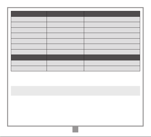
CARATTERISTICHE TECNICHE
RICEVITORE
- frequenza di ricezione ..................................................................................................... 433,92 / 868,3 MHz
- sensibilità (per segnale a buon ne).......................................................................................-110dBm 0,7µV
- modulazione ..............................................................................................................................................FSK
- impedenza di ingresso antenna............................................................................................................... 50 Ω
- alimentazione ricevitore .......................................................................................................................230Vac
- assorbimento a riposo/con tutti i relé attivati ..................................................................................20/40 mA
- massima potenza commutabile dal relé con carico resistivo:
carico in ac-dc ........................................................................................5 A max (3 A max RVQ504/508C1)
tensione massima ................................................................................................................................... 230V
- ritardo all'attivazione del relé....................................................................................................... 80 ÷ 100 ms
- regolazione trimmer modalità temporizzata.....................................................................................0 ÷ 250 s
- temperatura di esercizio.............................................................................................................-20°…+75 °C
TRASMETTITORE
- frequenza di trasmissione ...............................................................................................433,92 / 868,3 MHz
- potenza apparente irradiata .................................................................................-10…-7dBm (100-200 µW)
- modulazione ....................................................................................................................................... FM/FSK
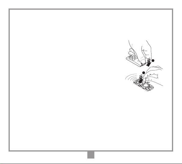
- alimentazione (batteria litio) .................................................................................................. 3V (1 x CR2032)
- assorbimento......................................................................................................................................... 18 mA
- temperatura di esercizio.............................................................................................................-10°…+55 °C
- umidità relativa........................................................................................................................................<95%
- tipo di codica ...............................................................................................................................rolling code
- numero di combinazioni complessive (128 bit):........................................................................................ 2128
- numero delle funzioni (canali).........................................................................................................................4
- autospegnimento:....................................................................................................dopo almeno 20 secondi
- portata (trasmettitori tascabili)......................................................................................................100 - 150 m
- portata (trasmettitori industriali) .............................................................................................................200 m
- portata (trasmettitori industriali con antenna esterna) ..........................................................................700 m

10
REMARKS
These instructions are aimed at professionally qualified "installers of electrical equipment" and must respect the
local standards and regulations in force. The use and installation of these appliances must rigorously respect the
indications supplied by the manufacturer and the safety standards and regulations in force.
This device complies with Part 15 of the FCC rules, and its operation is subject to the following two conditions: (1)
this device may not cause harmful interference, and (2) this device must accept any interference received, including
interference that may cause undesired operation. Changes or modifications made to this equipment not expressly
approved by Cardin may void the FCC authorization to operate this equipment. The radiated output power of the
device is far below the FCC radio frequency exposure limits. Nevertheless, the device shall be used in such a manner
that the potential for human contact during normal operation is minimized.
Attention! WEEE marking. This symbol indicates that once the products life-span has expired it must
be disposed of separately from other rubbish. The user is therefore obliged to either take the product to a
suitable differential collection site for electronic and electrical goods or to send it back to the manufacturer
if the intention is to replace it with a new equivalent version of the same product. Suitable differential collec-
tion, environmental friendly treatment and disposal contributes to avoiding negative effects on the ambient and
consequently health as well as favouring the recycling of materials. Illicitly disposing of this product by the owner
is punishable by law and will be dealt with according to the laws and standards of the individual member nation.
Description
The radio control system in "FM" consists of one or more transmitters and one or more receivers which can
be combined to meet the specic needs of the system. The receiver is able to memorise up to 1000 different
codes which are stored via radio in a non-volatile memory module located on the receiver.
Important: The transmitted code changes for each command (rolling code). If disturbance interrupts the
transmission, the receiver will wait for a different code, the relay can then only be activated by rst releasing
and then pressing the transmitter channel button again.
Use
The radio control allows the remote activation of electrical and electronic appliances with its best use
in the following areas: automatic opening systems, alarm systems, and in all systems which require
remote control activation (without wires) using secret codes.

11
Memory module
ZGB24LC64-I/P
The module is furnished with a none-volatile EEPROM type memory and contains the transmitter codes and allows
you to memorise up to 1000 codes. The programmed codes remain stored even in the absence of power.
Attention! Removing and inserting the memory module must be carried out when the receiver is switched off
otherwise the memory content could become corrupt.
PREPARING THE SYSTEM
To obtain the best results from the radio control system the aerial installation site should be carefully chosen. ‘Range’
is intended to mean the working distance, measured in free space, between the receiver and the transmitter with
the aerial installed. The range is therefore closely linked to the technical characteristics of the system and varies
according to the characteristics of the site in which the system is located. For best performance we advise you
to use the Cardin ANS400 / ANQ800-1 aerial. Wire the aerial to the receiver using a coaxial cable RG58
(impedance 50Ω) with a maximum length of 15 m.
433 MHz transmitters 868 MHz transmitters Description
TXQ504C2 TXQ508C2 2-channel precoded transmitters
TXQ504C4 TXQ508C4 4-channel precoded transmitters
TXQ504C8 TXQ508C8 8-channel precoded transmitters
TXQ504BD2
TXQ508BD2
2-channel precoded transceivers
TXQ504BD4
TXQ508BD4
4-channel precoded transceivers
TXQPRO504-4 TXQPRO508-4 4-channel precoded industrial transmitters
TXQPRO504-4A TXQPRO508-4A 4-channel precoded industrial transmitters + aerial
433 MHz receivers 868 MHz receivers Description
RVQ504C1 RVQ508C1 1-channel receiver - 230V
RVQ508C4 RVQ508C4 4-channel outdoor receivers - 230V

12
Transmitters
The transmitter is pre-coded and is tted with an integrated circuit which is programmed in the factory
with a unique identication number. All the code parameters are contained in this integrated circuit. The
transmitter has an automatic shut down mechanism which cuts in after at least 20 seconds of continuous
use (this limits battery consumption).
Key block function
• A key block function has been added to protect the appliance from
accidental activation;
- to activate the function press and hold down “MR” for 8 seconds until
the orange led starts ashing, at this point to activate a command you
will need to press the required key three times consecutively;
- to reset the function to standard operation, press and hold down “MR”
for 8 seconds until the orange led starts ashing.
Transceivers
The transceivers are tted with a buzzer which sounds to conrm the execution of the command and red
and green led lighting indicates the status of the relay (green = open, red = closed).
FASTENING THE OUTDOOR RECEIVER IP55 (fig. 4)
Open the four fastening holes as shown in the drawing using a screwdriver of similar tool. Trace the
four wall fastening points using the container as a template and then drill the holes (det. 3-4). Fasten
the container using four self-tapping screws M4,8 (det. 5). Once the container has been fastened insert
the screw covers. Remove the cable clamp covers and afx the two cable clamps as shown in detail 6.
Receiver electrical connection (g. 5/6)
RVQ504C1 / RVQ508C1 are tted with a 6-way terminal board and have a 230Vac electrical connection
between binding posts 1-2.
RVQ504C4 / RVQ508C4 are tted with an 18-way terminal board and have a 230Vac electrical
connection between binding posts 2-3.
1
2
MR

13
Setting up the 1-channel receiver RVQ504C1 / RVQ508C1 (g. 5)
The receiver can be set-up using the dip-switches S1:
To set the relay activation time move Dip 4 to position 'ON'; press 'P1' (LED 'L1'will ash and the time count
will start); premere 'P1' again (LED 'L1'remains lit and the time count will end); move Dip 4 to position 'OFF'.
Fixed position output relays RVQ504C4 / RVQ508C4
(g. 6)
The 4 output relays can be set via dip-switches (Dip1 = CHA - Dip2 = CHB - Dip3 = CHC - Dip4 = CHD) to
the following:
- Timer-controlled channel modules = corresponding dip-switch set to 'OFF'
- ON/OFF channel modules = corresponding dip-switch set to 'ON'
In the timer-controlled modules the activation time can be set by means of the trimmer T1 from 1 to 250 s.
Set Trimmer T1 to 0 sec. to enable the impulsive function.
To change the relay function mode (from timer controlled to ON/OFF and the other way round) the
receiver must be switched off and restarted.
Receiver code memory module M1
The codes are stored in a non-volatile EEPROM memory module.
The receiver is designed to manage up to 1000 users (1000 transmitters) with the possibility of memorising
and cancelling each individual user. For each transmitter it is possible to memorize a maximum of 4 functions.
The memorized codes are maintained in this module even in the absence of power for an unlimited period of time.
Bluetooth (only RVQ504C4 / RVQ508C4)
By inserting the module into the connector BT (g. 6) and downloading the application CRD ONE it is possible
to command the relays via Bluetooth. Tha App CRD ONE allows you to activate the receiver outputs (relays
CHA - CHB - CHC - CHD) and to monitor the status of the inputs (open/close).
dip 1 Memo radio
ON enabled
OFF disabled
dip 2 Relay On/Off
ON enabled
OFF disabled
dip 3 Timer-controlled
relay
ON enabled
OFF disabled
dip 4 Timer setting
max. 255 s
ON time count enabled
OFF time count disabled

14
Indications on the receivers
Red Led L1 - user management
- Flashing slowly: memorising a single user
- Flashing rapidly: cancelling a single user
- Continuously lit: memory full
SINGLE CHANNEL RECEIVER SYSTEM MANAGEMENT OPERATIONS (RVQ504C1 / RVQ508C1)
Attention! Before memorising the transmitters for the rst time remember to cancel the entire memory content.
• Memorizing a channel code
1. Press and hold down button "P1", LED "L1" will ash slowly.
2. At the same activate the transmitter channel to be memorised, "L1" will remain lit for 2 seconds
indicating that the channel has been memorised; if the LED keeps ashing slowly the channel was
already memorised. Only one channel can be memorised at a time. To insert another channel repeat
points 1 and 2 after having released the button. When the code memory is complete (1000 transmitters
memorised) you may only memorise a new transmitter after you have completely cancelled an existing
transmitter or after cancelling the entire memory content.
• Deleting a channel code (via an associated transmitter)
1. Press the button "P1" twice and hold down after pressing the second time: LED "L1" will ash at brief
intervals.
2. Activate the transmitter channel to be cancelled, "L1" will remain lit for 2 seconds indicating that the
channel has been cancelled;.
To cancel another channel repeat points 1 and 2 after having released the button.
• Deleting the entire code memory content (users)
- Press "P1" three and hold down after pressing the third time. During the cancellation procedure (3-4
seconds) LED "L1" remains lit. After cancellation the LED will ash 3 times; at this point release the
button.
Green Led L2 (only RVQ504C4 / RVQ508C4)
- Appliance "STATUS" LED
- Continuously lit: power on
- Flashing: no memory module present

15
4-CHANNEL RECEIVER SYSTEM MANAGEMENT OPERATIONS (RVQ504C4 / RVQ508C4)
Attention! Before memorising the transmitters for the rst time remember to cancel the entire memory
content.
• Memorizing a channel code
- Move the transmitter near to the receiver.
- Press and hold down the P1 MEMO button on the receiver and the LED L2 will ash slowly
- Press the button (channel) you wish to memorize on the transmitter.
- The LED L2 on the receiver will ash rapidly.
- Press the button (channel) you wish to memorize on the transmitter a second time.
The LED L2 on the interface will glow continuously and the buzzer will sound twice.
After a few moments led L2 will switch off.
- Release the P1 MEMO button. End of operation.
• Deleting a channel code (via an associated transmitter)
- Move the transmitter near to the receiver.
- Press and hold down the P2 DEL button on the receiver and the LED L2 will ash rapidly.
- Press the button (channel) you wish to delete on the transmitter.
- The LED L2 on the receiver will glow red continuously.
After a few moments Led L2 will switch off.
- Release the P2 DEL button. End of operation.
• Deleting the entire code memory content (users)
- Press and hold down the P1 MEMO and P2 DEL buttons for more than 4 seconds on the interface.
- LED L2 will remain lit for the entire duration of the deletion, which lasts for about 3 seconds
- LED L2 will ash for a few moments and then switch off.
- Release the buttons. End of operation.

16
MEMORIZZAZIONE CODICE TX-TX
TRQ504
29-10-2013
DM0910 Description :
Product Code :
Date :
Drawing number :
P.J.Heath
CARDIN ELETTRONICA S.p.A - 31020 San Vendemiano (TV) Italy - via Raffaello, 36 Tel: 0438/401818 Fax: 0438/401831
Draft :
All rights reserved. Unauthorised copying or use of the information contained in this document is punishable by law
MR
A
MR
B
1
2
3
MEMORIZZAZIONE CODICE TX-TX
TXQ504C4
29-10-2013
DM0911 Description :
Product Code :
Date :
Drawing number :
P.J.Heath
CARDIN ELETTRONICA S.p.A - 31020 San Vendemiano (TV) Italy - via Raffaello, 36 Tel: 0438/401818 Fax: 0438/401831
Draft :
All rights reserved. Unauthorised copying or use of the information contained in this document is punishable by law
A
MEMORIZZAZIONE CODICE TX-TX
TXQ504C4
29-10-2013
DM0912 Description :
Product Code :
Date :
Drawing number :
P.J.Heath
CARDIN ELETTRONICA S.p.A - 31020 San Vendemiano (TV) Italy - via Raffaello, 36 Tel: 0438/401818 Fax: 0438/401831
Draft :
All rights reserved. Unauthorised copying or use of the information contained in this document is punishable by law
B
• Memorizing more transmitters by using a previously memorised transmitter.
This procedure allows you to enable a new transmitter (from a remote position) with the help of a
transmitter that has already been memorised in the system. As the presence of the receiver is not
required this procedure can be carried out in any remote location (for example in your chosen sales
outlet).
Access to the "rapid memorizing" procedure can be enabled or disabled on the receiver by
inserting (or removing) the jumper R.MEMO (DIP2 S1 for the single channel receiver):
• Jumper J3 R.MEMO inserted: the rapid memorization procedure is enabled.
• Jumper J3 R.MEMO not inserted: the rapid memorization procedure is disabled.
- Remove the upper cover from the transmitter to be memorised and from the transmitter that has
already been memorised as shown in the drawing below (det. a).
- Place the transmitter A, that has already been memorised in the receiver, beside the new
transmitter B(det. b).
- Using a pointed object press and release the MR button on both transmitter (in sequence or
simultaneously).
- The orange LEDS on the transmitters will ash slowly.
- Press and release a channel button on transmitter Athat is already present in the receiver (det. c).
- The led of the new unit Bwill remain lit for 3 seconds to conrm memorization (det. d).
Transmitter Bwill now command the receiver exactly like transmitter A.

17
TECHNICAL SPECIFICATIONS
RECEIVER
- reception frequency.....................................................................................................
433,92 / 868,3
MHz
- sensitivity (nely tuned signal) ........................................................................................... -110dBm 0,7µV
- modulation ............................................................................................................................................ FSK
- antenna impedance in input.................................................................................................................50 Ω
- receiver power supply .................................................................................................................... 230Vac
- maximum power consumption at rest/with all relays activated................................................. 20/40 mA
- maximum commutable power at the relay with resistive load:
load ac-dc ............................................................................................ 5A max
(3 A max RVQ504/508C1)
maximum voltage ...............................................................................................................................230V
- relay activation delay time ......................................................................................................80 to 100 ms
- trimmer setting range .........................................................................................................................0 ÷ 250 s
- operating temperature range.................................................................................................-20°…+75 °C
TRANSMITTERS
- carrier frequency..........................................................................................................
433,92 / 868,3
MHz
- apparent radiated power................................................................................. -10…-7dBm (100-200 µW)
- modulation ......................................................................................................................................FM/FSK
- power supply (lithium battery) ...........................................................................................3V (1 x CR2032)
- power consumption...........................................................................................................................18 mA
- operating temperature range................................................................................................... -10…+55°C
- relative humidity................................................................................................................................. <95%
- type of encoding....................................................................................................................... rolling code
- total number of possible code combinations (128 bit) .........................................................................2
128
- number of channels................................................................................................................................... 4
- automatic shut down...........................................................................................after at least 20 seconds
- transmission range (miniaturised transmitters) ............................................................................100 - 150 m
- transmission range (industrial transmitters)............................................................................................200 m
- transmission range (industrial transmitters + aerial)...............................................................................700 m

18
AVERTISSEMENT
Ce livret est destiné à des personnes titulaires d’un certicat d’aptitude professionnelle pour l’installation "d'appareils
électriques" et requiert une bonne connaissance de la technique appliquée professionnellement. L’emploi et l’installation
de cet appareil doivent respecter rigoureusement les indications fournies par le constructeur et les normes de sécurité en
vigueur. Cet appareil, étant conforme à l’article 15 du règlement de la FCC, intitulé Operation (Utilisation), doit respecter
les deux conditions suivantes: (1) il ne doit pas causer de brouillage préjudiciable; et (2) il doit tolérer le brouillage, même
préjudiciable, causé par d’autres équipements. Les modications apportées à cet appareil sans autorisation expresse de
Cardin peuvent entraîner l'annulation de l'agrément de la FCC pour l'utilisation de cet appareil. La puissance rayonnée
de sortie de l'appareil est bien au-dessous des limites d'exposition aux radiofréquences de la FCC. Néanmoins, l’appareil
doit être utilisé de manière à réduire au minimum les risques de contact humain pendant le normal fonctionnement.
Attention! - Marquage WEEE. Ce symbole indique l’obligation de ne pas éliminer l’appareil, à la n de sa
durée de vie, avec les déchets municipaux non triés et de procéder à sa collecte sélective. Par conséquent,
l’utilisateur doit remettre l’appareil à un centre de collecte sélective des déchets électroniques et électriques
ou au revendeur qui est tenu, lorsqu’il fournit un nouvel appareil, de faire en sorte que les déchets puissent lui
être remis, sur une base de un pour un, pour autant que l’appareil soit de type équivalent à celui qu’il fournit. La collecte
sélective des équipements électriques et électroniques en vue de leur valorisation, leur traitement et leur élimination
dans le respect de l’environnement contribue à éviter la nocivité desdits équipements pour l’environnement et pour
la santé et à encourager leur recyclage. L’élimination abusive de l’équipement de la part du détenteur nal comporte
l’application des sanctions administratives prévues par les normes en vigueur dans l’État Membre d’appartenance.
Description
Lesystèmedetélécommanderadio en "FM" est constitué d'unou de plusieurs émetteurset d'un ou deplusieurs récepteurs,
qui seront combinés en fonction des exigences spéciques de l'installation. Le récepteur est en mesure de mémoriser
jusqu'à 1000 codes différents. En phase de mémorisation, les codes sont transférés dans une mémoire non volatile.
Important: Puisque à chaque commande le code émis change, si l'émission est interrompue par une perturbation,
il est nécessaire de délivrer à nouveau le signal en relâchant et en réappuyant la touche de l'émetteur car le récepteur
s'attend à recevoir un code différent.
Domaine d'application
La télécommande radio permet de commander à distance des appareils électriques et électroniques et trouve sa meilleure
application dans la commande de fermetures automatisées, systèmes d'alarme et dans toutes les installations qui
nécessitent une commande à distance (sans l) protégée par un code secret haute sécurité.

19
Module de mémoire ZGB24LC64-I/P
Constitué d’une mémoire non volatile type EEPROM, il contient les codes des émetteurs et permet la
mémorisationde1000codes.Danscemodule,lescodesrestentmémorisésmêmeencasdecoupuredecourant.
Attention!
Il est impératif de retirer et d’insérer le module de mémoire récepteur éteint, sous peine de
corrompre les données qu’il contient
.
PRÉDISPOSITION DE L’INSTALLATION
Pour bénécier de la portée maximale de ce système de télécommande, il est conseillé de choisir
soigneusementl’endroitd’installationdel’antenne.La portéeeststrictementliée auxcaractéristiquestechniques
dusystèmeetvarieen fonction descaractéristiquesdulieud’implantation. Par portée,nousentendonsladistance
nécessaire, entre les signaux transmis et reçu, pour une issue positive. Pour optimiser le fonctionnement de
l’installation, il est conseillé d’utiliser l’antenne Cardin ANS400 / ANQ800-1. Brancher au récepteur l’antenne
accordée au moyen d’un câble coaxial RG58 (impédance 50Ω) d’une longueur maximale de 15 m.
Émetteurs 433 MHz Émetteurs 868 MHz Description
TXQ504C2 TXQ508C2 Émetteurs pré-codé 2 fonctions
TXQ504C4 TXQ508C4 Émetteurs pré-codé 4 fonctions
TXQ504C8 TXQ508C8 Émetteurs pré-codé 8 fonctions
TXQ504BD2 TXQ508BD2 Transceiver
pré-codé 2 fonctions
TXQ504BD4 TXQ508BD4 Transceiver
pré-codé 4 fonctions
TXQPRO504-4 TXQPRO508-4
Émetteurs industriels pré-codé 4 fonctions
TXQPRO504-4A TXQPRO508-4A
Émetteurs industriels pré-codé 4 fonctions + antenne
Récepteurs 433 MHz Récepteurs 868 MHz Description
RVQ504C1 RVQ508C1 Récepteurs 1 canal - 230V
RVQ504C4 RVQ508C4 Récepteurs sous coffret 4 canaux - 230V

20
Émetteur
L'émetteur est précodifié et utilise un circuit intégré, programmé à l'usine avec un numéro d'identication,
unique pour chaque émetteur; tel circuit porte en lui-même tous les paramètres nécessaires au codage.
L'émetteur est doté d'un mécanisme d'autoextinction qui se déclenche au moins 20 secondes après une
activation continue (pour réduire la consommation de la pile).
Fonction de verrouillage des touches
• L'émetteur a la possibilité d’introduire la fonction de verrouillage des touches,
fonction qui protège l’appareil contre les activations impromptues;
- pouractiverla fonction, garder lebouton “MR”appuyépendant 8 secondes
jusqu'à ce que la led orange clignote ; à ce point, pour délivrer une
commande,ilfaudra appuyer troisfoisdesuite surlatouche correspondante;
- pour rétablir la fonction standard, garder le bouton “MR” appuyé pendant
8 secondes jusqu'à ce que la led orange clignote.
Émetteurs bidirectionnels
Les émetteurs bidirectionnels sont équipés d’une signalisation acoustique conrmant l’exécution de
la commande et d’une signalisation lumineuse à Led rouge et verte indiquant l’état des relais dans les
récepteurs (Led verte ouvert, Led rouge fermé).
Fixation du récepteur sous coffret IP55 (g. 4)
Désoperculer les 4 trous de xation, comme le montre la gure (dét. 2) avec un tournevis ou un outil
similaire. Tracer les quatre points de xation au mur à l'aide du coffret et percer les trous (dét. 3-4). Fixer
le coffret avec quatre vis autotaraudeuses M4,8 (dét. 5). Une fois le coffret xé, appliquer les caches-vis.
Retirer les couvercles appliqués sur les trous prévus pour la mise en place des presse-étoupes et insérer
les deux presse-étoupes, comme le montre le détail 6.
Branchement récepteur (fig. 5/6)
RVQ504C1 / RVQ508C1 sont dotées d’un bornier à 6 voies, avec alimentation 230Vac entre les bornes 1 et 2.
RVQ504C4 / RVQ508C4 sont dotées d’un bornier à 18 voies, avec alimentation 230Vac entre les bornes 2 et 3.
1
2
MR
Other manuals for S504 Series
3
This manual suits for next models
19
Table of contents
Languages:
Other Cardin Remote Control manuals

Cardin
Cardin S449 QZ2 Owner's manual

Cardin
Cardin S449 User manual

Cardin
Cardin S449 QZ2 Owner's manual

Cardin
Cardin S48 Series User manual

Cardin
Cardin FM S449 Series User manual

Cardin
Cardin S38 Series User manual

Cardin
Cardin S449 User manual

Cardin
Cardin S435 Series User manual

Cardin
Cardin S486 Series User manual

Cardin
Cardin ZVL558.00 User manual