3500-0418-0M Rev A • DB-SP Load Cell Kits
SPECIFICATIONS, CONT.
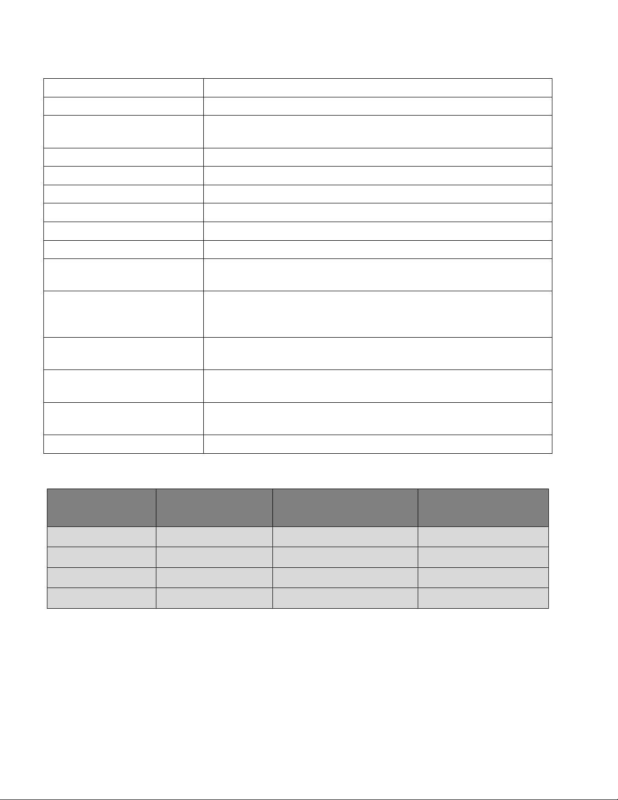
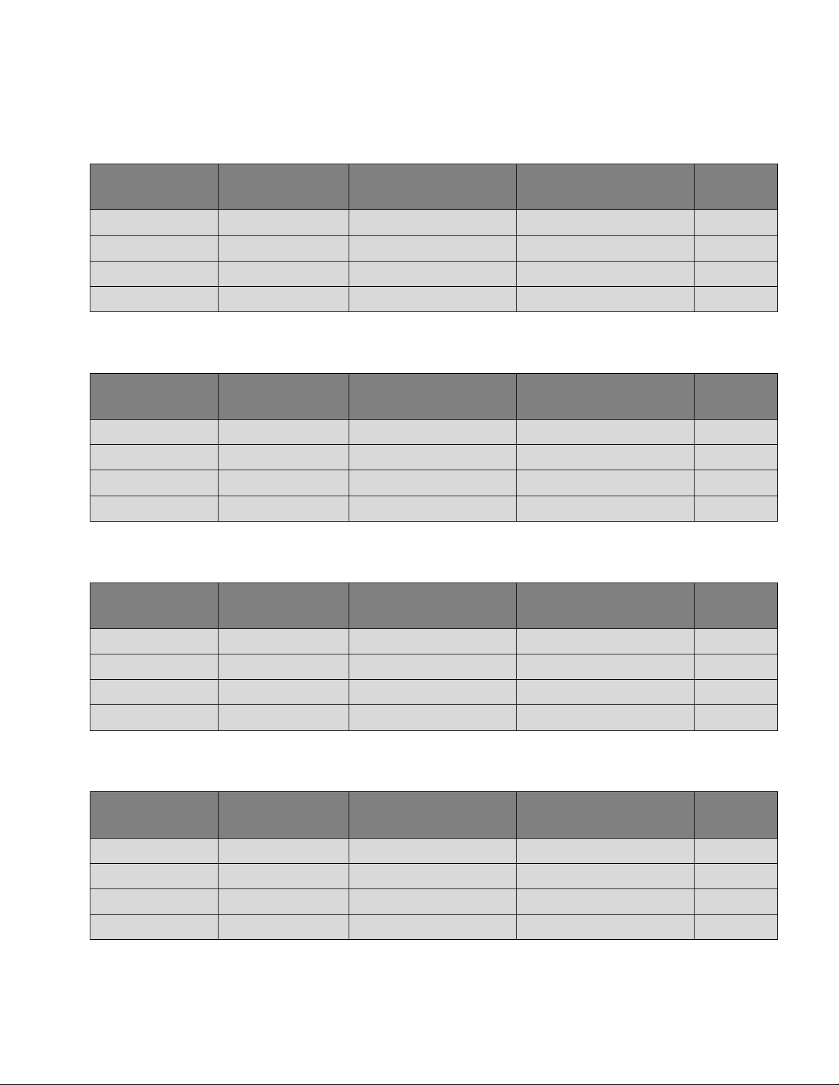
System Capacities
3 Load Cell Systems | Mild Steel Stands
MODEL LOAD CELL
CONSTRUCTION
LOAD CELL
CAPACITY
SYSTEM
CAPACITY
SHIPPING
WEIGHT
DB-20000SP-3 Stainless Steel 20,000 lb / 9,070 kg 60,000 lb / 27,215 kg 94 lb
DB-30000SP-3 Stainless Steel 30,000 lb / 13,605 kg 90,000 lb / 40,825 kg 343 lb
DB-50000SP-3 Stainless Steel 50,000 lb / 22,700 kg 150,000 lb / 68,040 kg 343 lb
DB-75000SP-3 Stainless Steel 75,000 lb / 34,000 kg 225,000 lb / 100,000 kg 343 lb
3 Load Cell Systems | Stainless Steel Stands
MODEL LOAD CELL
CONSTRUCTION
LOAD CELL
CAPACITY
SYSTEM
CAPACITY
SHIPPING
WEIGHT
DB-20000SPS-3 Stainless Steel 20,000 lb / 9,070 kg 60,000 lb / 27,215 kg 94 lb
DB-30000SPS-3 Stainless Steel 30,000 lb / 13,605 kg 90,000 lb / 40,825 kg 343 lb
DB-50000SPS-3 Stainless Steel 50,000 lb / 22,700 kg 150,000 lb / 68,040 kg 343 lb
DB-75000SPS-3 Stainless Steel 75,000 lb / 34,000 kg 225,000 lb / 100,000 kg 343 lb
4 Load Cell Systems | Mild Steel Stands
MODEL LOAD CELL
CONSTRUCTION
LOAD CELL
CAPACITY
SYSTEM
CAPACITY
SHIPPING
WEIGHT
DB-20000SP-4 Stainless Steel 20,000 lb / 9,070 kg 80,000 lb / 36,280 kg 124 lb
DB-30000SP-4 Stainless Steel 30,000 lb / 13,605 kg 120,000 lb / 54,420 kg 456 lb
DB-50000SP-4 Stainless Steel 50,000 lb / 22,700 kg 200,000 lb / 90,800 kg 456 lb
DB-75000SP-4 Stainless Steel 75,000 lb / 34,000 kg 300,000 lb / 136,000 kg 456 lb
4 Load Cell Systems | Stainless Steel Stands
MODEL LOAD CELL
CONSTRUCTION
LOAD CELL
CAPACITY
SYSTEM
CAPACITY
SHIPPING
WEIGHT
DB-20000SPS-4 Stainless Steel 20,000 lb / 9,070 kg 80,000 lb / 36,280 kg 124 lb
DB-30000SPS-4 Stainless Steel 30,000 lb / 13,605 kg 120,000 lb / 54,420 kg 456 lb
DB-50000SPS-4 Stainless Steel 50,000 lb / 22,700 kg 200,000 lb / 90,800 kg 456 lb
DB-75000SPS-4 Stainless Steel 75,000 lb / 34,000 kg 300,000 lb / 136,000 kg 456 lb