UI MultiAdjust User Guide. iss1 07/21
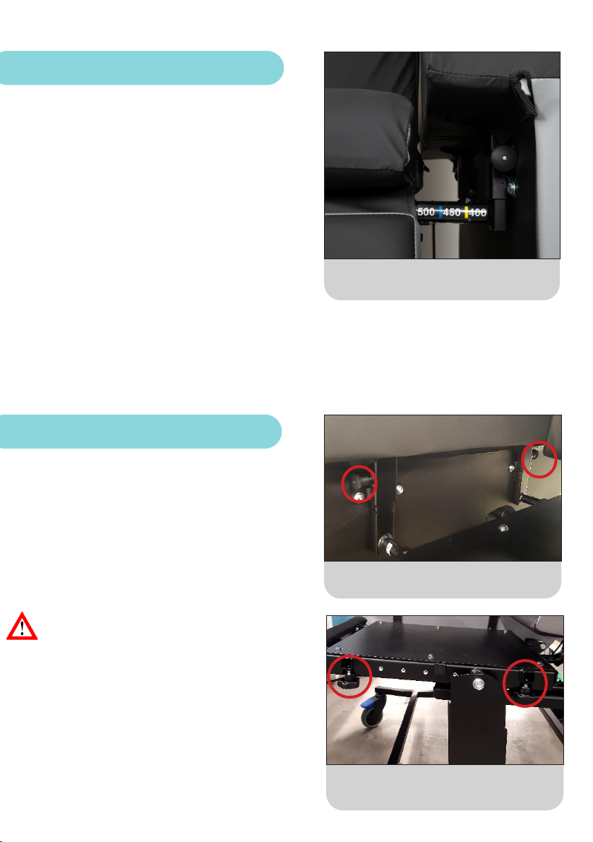
6. Seat Width
The MultiAdjust has a width size guide
on each arm to assist with adjustments.
Correct seat width is important for the user’s lateral
stability. To adjust seat width, each arm rest can be
moved in or out:
• Locate the two hand wheels; one is located at the
front of the seat base and one at the rear.
• Turn in clockwise direction to loosen.
• To reduce seat width, move the arm rests inwards
to the centre of the chair by placing the palm of
the hand on the outside face of the arm rest and
push.
• To increase seat width, move the arm rests
outwards by placing the palm of the hand on the
inside face of the arm rest and push.
• Once the desired seat width is achieved, turn the
hand wheels in anti-clockwise direction to lock the
arm rests in position.
• Arm rests can be set at dierent seat widths
from front to back and left to right, which may be
indicated for users with xed lower limb postures
such as windsweeping, or those with increased
body mass in the gluteal and hip areas.
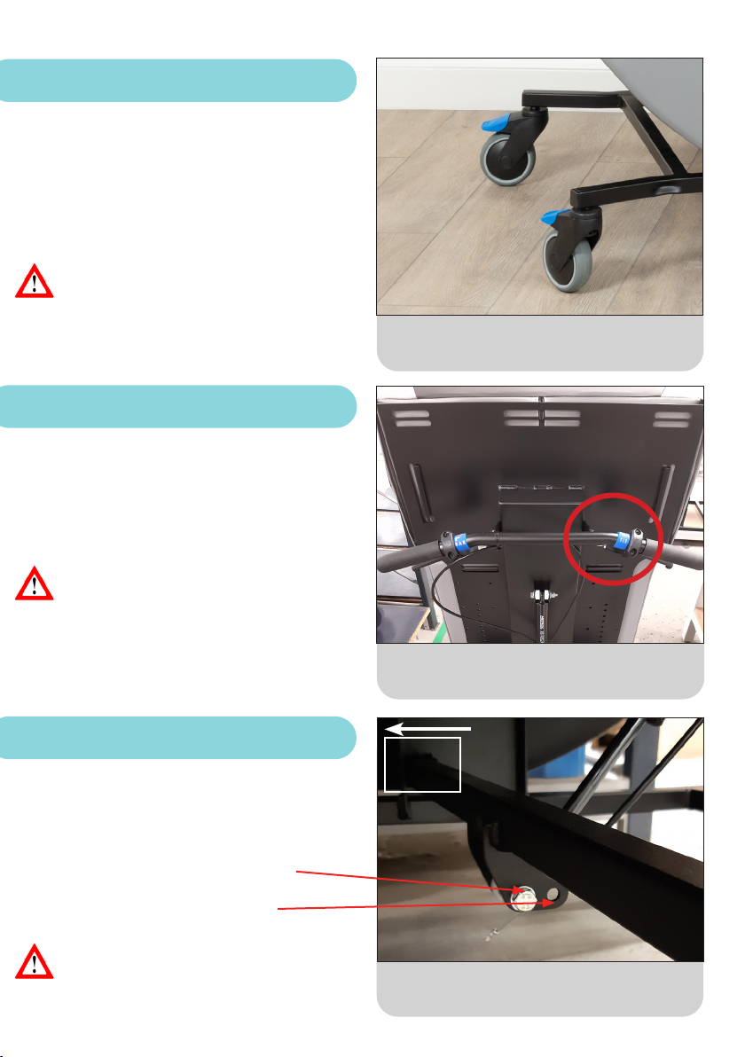
Location of the hand wheels underneath
the seat base for seat width and arm
removal.
7. Arm Rest Height and Removal
• To adjust arm rest height, locate the two plunger
pins located on the inside of the arm rest; one
towards the front and one towards the rear.
• With a plunger pin in each hand pull out.
• Slide the arm up or down, to adjust to the desired
height.
• Release the plunger pins to lock into position.
• Arm rest height can be set dierently from front
to back resulting in angled arm rests, which may
be indicated for users with specic upper limb
positioning requirements.
• Arm rest height should be based on the outcome
of the user’s assessment; please refer to these
measurements or seek further guidance from
the Health Care Professional.
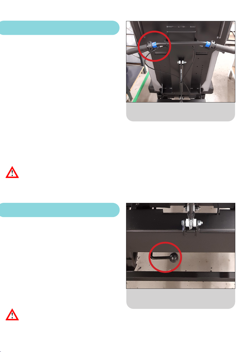
Plunger pins located on the inside of the
arm rest.
The arm rests can be removed to aid user transfers,
positioning, cleaning and servicing:
• Locate the two hand wheels; one is located at the
front of the seat base and one at the rear.
• Turn in clockwise direction to loosen.
• The arm rest can then be removed completely.
5