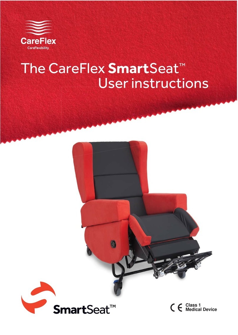
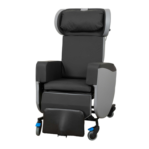
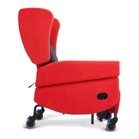
CareFlex SmartSeatPro II Instruction manual

UI SmartSeatPro II User Guide. Iss1 06/22
UI
SmartSeatPro II
Quick User Guide
The SmartSeatPro II, our revolutionary modular chair has
evolved, taking specialist seating to a whole new level.
This seating system is highly adjustable and adaptable
for individuals with complex posture and pressure
management needs.
WARNING
A level of supervision appropriate to the user’s abilities should be
applied at all times.
Medical Device
Class 1

UI SmartSeatPro II User Guide. Iss1 06/22
2
Index
Page Contents
3 Introduction
4 Technical Drawings
5 Chair Overview & Options
6 Braking System
7 Tilt-in-Space
9 Back Angle Recline
11 Leg Rest
12 Footplate
13 Armrest Height & Removal
14 Seat Cushion
15 Seat Width
16 Seat Depth
17 Seat Height
18 Back System Configurations & Options
20 Back Adjustments
22 Head & Wing Adjustments
24 Headrests (Accessory)
26 Pommel (Accessory)
27 Lateral (Accessory) & Selection Guide
31 Tray (Accessory)
32 Positioning Aids (Accessory)
26 Battery (Motorised Option)
37 Looking After Your Chair & Safety
38 Maintenance & Servicing
39 Identification Label & Notes

UI SmartSeatPro II User Guide. Iss1 06/22
3
The SmartSeatPro II Chair User Guide
These are the user instructions for the SmartSeatPro II specialist seating system from
CareFlex.
Please read them carefully before using the chair and keep them safe in a place for
future reference.
These instructions include details of the performance of
the chair. If the chair should start behaving outside of its
intended performance, show signs of damage or excessive
wear, or otherwise feel unsuitable, please take it out of service
and contact CareFlex or your regional CareFlex distributor
immediately.
It is possible to store the user instruction booklet inside the
wing upholstery of the head support cushion by unzipping
the aperture on the rear of the cushion and sliding the booklet
inside.
• If you are in any doubt about the safe operation of the SmartSeatPro II,
contact your CareFlex Customer Support or your local CareFlex distributor for
clarification and further training.
The SmartSeatPro II is a highly adjustable modular seating system for adults that
takes specialist seating to the next level for those with complex postural management
and pressure care needs. The SmartSeatPro II’s unique design allows for a range of
configurations to ensure postural asymmetries can be fully stabilised, accommodated,
and, where possible, corrected from the feet, through the pelvis and spine, and to the
head.
The SmartSeatPro II benefits from Tilt-in-Space, Back Angle Recline, and a multi-
adjustable back and head system with new sections of modifiable filling. The chair’s
design gives Health & Social Care Professionals maximum adaptability to optimise
posture, function and comfort for individuals in all environments, including domestic
settings, schools, care homes and hospitals. Operation of chair functions can be
by either manual gas action control or battery-controlled motors with a pro-control
option. The chair provides high levels of comfort and the robust construction quality
associated with CareFlex chairs. The SmartSeatPro II comes with a Lifetime Frame
Warranty for extra peace of mind.
• These pressure care features make the SmartSeatPro II suitable for those at risk
of pressure injury when used as part of a management programme assessed and
prescribed by an appropriate Health & Social Care Professional.
The SmartSeatPro II Introduction

UI SmartSeatPro II User Guide. Iss1 06/22
4
The SmartSeatPro II Technical Drawings
(All measurements ±10mm / 5°)
Weights Kilograms
Chair Weight - Manual (Standard Specification) 77kg
Chair Weight - Manual (Ratchet Arm Option) 85kg
Chair Weight - Motorised (Standard Specification) 83kg
Chair Weight - Motorised (Ratchet Arm Option) 91kg
Maximum User Weight 160kg

UI SmartSeatPro II User Guide. Iss1 06/22
5
The SmartSeatPro II Overview
Choice of Actuation Formats
Manual Format
On the manual version of the SmartSeatPro II chair the Tilt-in-Space, Back Angle
Recline and the elevating leg rest are controlled by locking gas actions.
Motorised Format
On the motorised version of the SmartSeatPro II chair the Tilt-in-Space, Back Angle
Recline and the elevating leg rest are controlled by electric actuators, which are
powered by a rechargeable 24V battery system.
Pro-Control Format
On the pro-control version of the SmartSeatPro II chair the Tilt-in-Space and the
elevating leg rest are controlled by electric actuators, which are powered by a
rechargeable 24V battery system. Back Angle Recline is controlled by a locking gas
action.
FEATURES
• New Multi-Adjustable and Modifiable Back
and Head System
• Tilt-in-Space with New Inclinometer (Visual
Tilt Angle Indicator)
• Back Angle Recline with New Visual Indicator
• WaterCell Technology
• New Increased Negative Angle, Channelled
and Elevating Leg Rest
• New Angle Adjustable Flip-Up Footplate
• New Integral Seat Depth Adjustment
• New Integral Seat Width Adjustment
• New Integral Arm Height Adjustment
• New Adjustable and Removable Armrests
• New Hoist and Transfer Friendly Frame with
Increased Ground Clearance
• Four Fully Braked Castors
• New Removable Battery Tray on Motorised
Versions
OPTIONS
• Back and Head Adjustment
Kits (Lever Adjustment or
New Quick-Release)
• Back Depth Adjustment
Upgrades
• New Armrest Upgrade with
Quick Ratchet Adjustments
• New Ergonomically Shaped
Lateral Supports (option to
use two supports on each
side)
• Range of Head Supports
• Range of Positioning Aids
• Range of Footplate Supports
• New Adjustable and Swivel
Head Pommel
• Tray
• Tailored Seating Solutions

UI SmartSeatPro II User Guide. Iss1 06/22
6
• To release the brakes, gently kick
the end of the lever that is pointing
upwards (B).
• The lever will snap up and the castors
will roll freely.
• Always brake the castors before
transferring the user into or out of
the chair.
1. Brakes
During transfers into and out of the chair it is important that the chair is as stable as
possible.
The chair is fitted with four fully braked castors, and at least TWO of the castors
should be engaged with brakes on prior to transfer.
• To lock the brakes, position the chair
approximately where you need it to
be for transfer.
• Gently push the chair away from you
so that the castors swivel around and
the blue brake levers can be easily
accessed.
• Press down the end of the brake
levers with your foot (A). The lever
will angle down and click into the
locked position.
1a. Locking the Brakes
1b. Releasing the Brakes
B) Braked
A) Unbraked

UI SmartSeatPro II User Guide. Iss1 06/22
7
2a. Tilt-in-Space Operation
Squeeze the right-hand lever to
operate Tilt-in-Space.
Manual Format:
Tilt-in-Space is controlled with the lever on
the right-hand side of the push handle at the
back of the chair:
• To adjust the angle of tilt, squeeze
the lever (A) and tilt the chair to the
desired angle. Release the lever to
lock the chair at the desired angle.
• Do not attempt to raise the user to a
standing position when the chair is
tilted backwards.
Motorised Format:
On motorised chairs, the second row of
buttons on the handset controls the Tilt-
in-Space angle adjustment.
• Tilt-in-Space should always be
prescribed responsibly, ensuring
that it is safe and appropriate for
the user following a comprehensive
assessment of posture and risk,
with advice sought from the multi-
disciplinary team where indicated.
In some cases, this function will be
contra-indicated.
A
2. Tilt-in-Space
The SmartSeatPro II chair has a Tilt-in-Space function which allows the user to be
tilted without adjusting the critical angles for sitting at the hips and knees. This helps
the user to maintain a stable sitting posture whilst redistributing their weight over a
large surface area.
• Tilt-in-Space should be regularly adjusted to facilitate an easy change in
position and weight distribution, thus avoiding pressure build up in any one
area.
• Always warn the user before changing the Tilt-in-Space setting to ensure that
they do not become distressed or agitated, which could impact on postural
stability.
• The chair will tilt approximately 35obackwards. This degree of tilt angle may be
disconcerting for some individuals.
• When tilting the SmartSeatPro II chair forward, ensure that the footplate height
is set so that the footplate will not hit the floor.
Motorised remote
(A pro-control remote differs to this).

UI SmartSeatPro II User Guide. Iss1 06/22
8
2b. Tilt-in-Space Use &
Inclinometer
Tilt-in-Space inclinometer.
• Seat to back angle remains the same
– the whole system tilts posteriorly.
• Promotes pelvic stability.
• Encourages pressure redistribution.
• Manages energy levels.
• Assists with hoisting and positioning.
• Tilt angle will be dependent on safety,
tolerance, and appropriateness.
• The new informative inclinometer (A)
will aid seating prescription and safe
use.
A

UI SmartSeatPro II User Guide. Iss1 06/22
9
3a. Back Angle Recline Operation
Squeeze the left-hand lever to
operate Back Angle Recline.
Manual Format:
On the manual format chair the Back
Angle Recline feature is controlled by the
lever positioned on the left-hand side (B)
of the push handle and labelled with a
blue band as shown.
To adjust the angle of recline, grip the
handle bar firmly. With the left hand,
use your index finger to locate the small
locking lever which is fitted in front of
the main lever (B). Once the locking
lever has been activated, the main lever
can then be squeezed to adjust the back
angle.
• Do not attempt to raise the user to a
standing position when the chair is
in recline.
Motorised Format:
On motorised chairs, the third row of
buttons on the handset controls the Back
Angle Recline adjustment.
B
3. Back Angle Recline
The SmartSeatPro II chair has a Back Angle Recline function which is used to adjust
the angle between the seat and the back, thus opening/closing the hip angle.
Always warn the user before changing the Back Angle Recline setting to ensure that
they do not become distressed or agitated, which can affect postural stability.
The chair back angle can be adjusted between approximately 90oto 125o. The forward
position provides a more comfortable setting for meal times and activities, and the
rearward setting is more suited to resting.
• Back Angle Recline should always be prescribed responsibly, ensuring that it
is safe and appropriate for the user following a comprehensive assessment of
posture and risk, with advice sought from the multi-disciplinary team where
indicated. In some cases, this function will be contra-indicated, and it could also
increase shear and friction forces.
Motorised Back Angle Recline
(A pro-control remote differs to this).

UI SmartSeatPro II User Guide. Iss1 06/22
10
2a. Back Angle Recline Use
& Indicator
Back Angle Recline indicator -
indicating every 15o(90o- 125o).
• Seat to back angle adjusts to open up
the hip angle.
• Assists with comfort and reduces
abdominal pressure.
• Accommodates reduced hip flexion
range of movement, and helps
alleviate any associated pain.
• Back angle will be dependent on
hip range of movement and pelvic
stability.
• The visual back angle indicator (A)
for degree of recline will aid seating
prescription and safe use.
A

UI SmartSeatPro II User Guide. Iss1 06/22
11
3a. Leg Rest Operation
Locate the lever on the right-hand
side of the leg rest.
Manual Format:
The leg rest can be elevated to promote
comfort during periods of rest, manage
oedema, or to achieve a change of
position:
1. Locate lever at the right-hand side of
the leg rest.
2. Squeeze the lever then lift or lower
the leg rest to the desired angle.
3. Release lever to lock the position.
4. To lower the leg rest, squeeze the
lever and push the leg rest to return it
to it’s lowered position.
• Never leave the user unsupervised in
the chair with the leg rest elevated.
• Leg rest elevation should only be
used within the ranges tolerated by
the user based on their knee range
of movement and should not affect
pelvic stability.
Motorised Format:
On the motorised format chair, the leg
rest elevation is controlled by the handset.
The top row of two buttons control the
elevation. The left hand button raises the
leg rest, and the right hand button lowers
the leg rest.
3. Leg Rest
The SmartSeatPro II has an integral leg rest which can be elevated to support the legs.
The leg rest mechanism articulates, following the movement of the knee as it elevates
the legs. The leg rest incorporates visco-elastic memory foam for pressure care.
• Ensure the leg rest is fully lowered before transferring an individual into or out of
the chair.
• The range of leg rest elevation is from 60oto 160o. The range of elevation
tolerated by the user will depend on knee range of movement. If tightness in
the hamstrings muscles or contractures in the knees are present then to ensure
comfort and postural stability it is critical that the leg rest is not over-elevated.
Close attention to the length of time the leg rest elevation is utilised is also
needed.
Motorised remote
(A pro-control remote differs to this).

UI SmartSeatPro II User Guide. Iss1 06/22
12
Locating the plunger pin.
Parts of the footplate.
The footplate fits into the bracket
on the back of the leg rest.
4. Height & Angle Adj. Flip-up Footplate UK Patent Approved
GB 2589439
A footplate is important for the user’s comfort, postural
stability and pressure distribution. The SmartSeatPro
II footplate is also suitable for users with a longer lower
leg length. The footplate is xed into a bracket on the
back of the leg rest. To insert and adjust the footplate
height:
1. Pull out the locating pin on the bracket and insert
the footplate.
2. Slide the footplate up or down to adjust to the
desired height.
3. Release the locking pin; the pin should ‘click’ into
position when the footplate is properly located.
• Note: The footplate stem has a ratchet and wheel
safety feature. This ensures that should the
footplate come into contact with the oor it will rise
up out of the way maintaining chair stability. The
wheel oers some protection to the ooring.
• The ratchet feature is predominantly for safety;
we advise that the footplate height is reduced by
hand every time the leg rest is lowered.
The footplate can be adjusted and set to a choice of 4 positions; 75°, 90°, 105° & 120°.
This equates to a 120° range of adjustment. In all angled positions the footplate can be
easily lifted up to 0o (vertical) to move it out of the way.
The SmartSeatPro II footplate angle can be adjusted
to correct positioning at the feet to neutral, or
accommodate xed postures at the ankles. To adjust
the footplate angle:
1. Ensure this operation is carried out by a competent
person, and that no weight is being applied to the
footplate.
2. The position is set by the plunger pins as shown;
each indicator oers 1 of 4 dierent positions
and 0ois achieved when vertical. Pull out one of
the plungers and twist so that it is locked o (see
image).
3. With one hand safely on the footplate, pull out the
second plunger pin so that the footplate can angle
to the desired setting.
4. When this is achieved, lock both plunger pins into
position, fully engaging with the corresponding
holes on each side.
5. The footplate will ‘ip-up’ to vertical 0ofrom any
position and return to its original setting.
• Keep ngers away from the mechanism when
performing this task to avoid any potential nger
traps.
Unlocked Locked

UI SmartSeatPro II User Guide. Iss1 06/22
13
5. Armrest Height Adjustment & Removal
To adjust the armrest height, locate the two
plunger pins on the inside of the armrest;
one towards the front and one towards the
rear.
1. With a plunger pin in each hand, pull
both outwards to disengage.
2. Slide the arm up or down to adjust to
the desired height.
3. Release the plunger pins to lock into
position, and you should hear an
audible click.
4. Armrest height can be set differently
from front to back, resulting in angled
armrests, which may be indicated
for users with specific upper limb
positioning requirements.
5. The armrest height should be based on
the outcome of the user’s assessment;
please refer to these measurements or
seek further guidance from the Health
and Social Care Professional.
The armrests (A) can be removed to aid
user transfers, positioning, cleaning and
servicing:
1. Locate the two quick release levers;
one is located at the front of the seat
base and one at the rear.
2. Pull in an upwards motion to loosen.
3. The armrest can then be removed.
The armrest can be removed
completely for side transfers.
5a. Ratchet Height Adjustment
Armrest Upgrade
CareFlex offers an upgrade to the
armrests, which uses a ratchet mechanism
for simple and regular arm height
adjustments between 200mm to 270mm
from the seat cushion.
• With the armrest attached to the
chair, lift it upwards; as it raises, you
will hear audible clicks which move
in 13mm increments. The armrest
height will be set in position after each
audible click.
• To lower the armrest, raise it entirely
to the top of its travel; you will then be
able to lower the armrest back to its
lowest setting.
Plunger pins located on the inside of
the armrest.
Ratchet mechanism upgrade for
armrest height.
A

UI SmartSeatPro II User Guide. Iss1 06/22
14
6. Seat Cushion
The SmartSeatPro II comes with a choice of two seat module widths, which would
have been specified at the assessment. The specification of these is for comfort and
safety; recommended widths are as stated:
Standard Cushion – For users with a seat width of less than 450mm.
Large Cushion – For users with a seat width of 450mm and above.
6a. Seat Cushion Removal
It may be necessary to remove the seat
cushion to access parts of the chair and
for cleaning and replacing the cushion.
To remove the seat cushion:
1. Unlock the cam lock buckles on the
front of the seat and pull the straps
through.
2. Detach the Velcro connecting the
leg rest to the underside of the seat
module.
3. Unclip the two plastic J clips at the
back and pull them out of the slot.
4. Now remove the seat.
5. To fit or re-fit the seat re-attach
in the reverse order, ensuring the
straps are pulled tight to reduce seat
movement.
1
2
3
Location of the seat cushion buckles
and Velcro.
Location of the seat cushion rear J
clips.

UI SmartSeatPro II User Guide. Iss1 06/22
15
7a. Adjusting Seat Width
Quick release levers.
LEVER
NUT
LOCK / UNLOCK
To adjust seat width, each armrest can be
moved in or out:
• Locate the two quick release levers;
one is located at the front of the seat
base and one at the rear.
• Pull in an upwards motion to UNLOCK
• To reduce seat width, move the
armrests inwards to the centre of the
chair by placing the palm of the hand
on the outside face of the armrest and
push.
• To increase seat width, move the
armrests outwards. Hold each side of
the arm securely with both hands, one
towards the front of the chair and one
near the rear. Gently pull to the desired
position.
• Once the desired seat width is
achieved, lower the levers to LOCK the
armrests in position.
• Armrests can be set at different
seat widths from front to back and
left to right, which may be indicated
for individuals with fixed lower limb
postures such as wind sweeping, or
those with increased body mass in the
gluteal and hip areas.
• This may cause some superficial
damage to the seat width stickers if
undertaken without care.
• If required over time, the quick release
levers can be tightened or loosened,
by holding the lever in an unlocked
position and turning the nut (clockwise
to tighten & anti-clockwise to loosen).
The SmartSeatPro II has a width size
guide on each arm.
7. Seat Width
Seat width adjustment helps to laterally stabilise the pelvis. Correct seat width can
reduce the tendency for the user to lean or shuffle the pelvis. These undesirable
movements can result in pelvic obliquity or pelvic rotation and the posture becoming
increasingly unstable with unequal loading on tissues. Left unmanaged, this leaning
posture could lead to the development of a scoliosis.
• Seat width should generally allow for a small amount of movement as the user’s
body weight and posture naturally shifts throughout the day. If the user is held in
a rigid position, they can fatigue quickly and experience discomfort.

UI SmartSeatPro II User Guide. Iss1 06/22
16
Locate the lever at the back of the
chair.
8a. Seat Depth Adjustment
Appropriate seat depth is critical to the
performance of the chair and the user’s
postural stability. To adjust seat depth:
1. Locate the lever (A) at the back and
left-hand side under the chair.
2. Twist lever down and pull/push the
seat frame (B) on right-hand side until
seat depth is in desired position.
3. Release the lever and pull the handle
until the seat “clicks” positively into
position.
• Never adjust the seat depth when
the user is in the chair or when the
chair is reclined.
8. Seat Depth
It is critical to set seat depth correctly in order to prevent ‘sacral sitting’ and to achieve
the best distribution of weight between the user and the chair.
• Sacral sitting occurs when the pelvis tilts backwards. The sacral area can be
susceptible to pressure problems. Sacral sitting will occur if the seat depth is
set too long. If the seat depth is too short then the area over which body weight
is distributed may be reduced, which can increase the risk of pressure injury.
• Seat depth should be set with the user’s pelvis positioned firmly at the back of
the seat cushion so that their lower back and lumbar is supported by the back
cushion. There should be a two or three finger gap between the back of the
user’s knee and the front of the seat cushion for comfort.
• If the individual already has a chair or wheelchair with the correct seat depth,
measure this size and use it as a starting point for setting the SmartSeatPro II.
Twist lever down.
B
A

UI SmartSeatPro II User Guide. Iss1 06/22
17
9. Seat Height
• If the user can raise to standing themselves or with minimal assistance, the
seat height should be set so that the user’s feet rest flat on the floor and the
underside of their thighs are in contact with the full length of the seat cushion.
• If the seat height is too high, the user’s heels may be lifted off the floor and
pressure will build up along the underside of their thighs. If the seat is too low,
their knees will be raised and there will be no contact between the back of their
thighs and the seat cushion, increasing the pressure on their bottom and sacrum.
• If the user is less ambulant then the seat height can be set reference to the
footplate, again ensuring the foot is flat and fully supported.
• The SmartSeatPro II will have been measured at assessment and manufactured
to the preferred dimensions.
9a. Seat Height Adjustments
• If further adjustment is necessary,
remove both armrests and carefully
place chair on its side. Remove the
four bolts on either side using a
13mm spanner and reposition into
the desired holes, repeat on the
other side.
• See diagram below for seat height
bolt positions.
• This should only be carried out by
a trained person or technician.
Seat height adjustment bolts.
Seat height measurements.

UI SmartSeatPro II User Guide. Iss1 06/22
18
10. Back Configurations & Adjustments
The SmartSeatPro II has a unique
multi-adjustable back and head system
that consists of four individual cushion
elements providing postural support for:
1. Sacral region
2. Lumbar region
3. Thoracic region
4. Cervical region
10a. Back Adjustment Options
To maintain the integrity of individual postural management settings, key
adjustments on the back are adjustable using a 10mm swan neck spanner or socket.
Alternatively, CareFlex offer three back section fixing methods, which would have
been specified on assessment:
1. Bolts (standard option)
2. Lever Lock (upgrade option)
3. Quick Release (upgrade option)
10b. Back Adjustments - Bolts
As standard the back sections will be
fixed to the centre pillar with M6 bolts;
these can be adjusted by using a 10mm
spanner.
To adjust, partially loosen the bolts in
an anticlockwise direction, set the back
section as required and tighten the bolts
in a clockwise direction. This method is
preferred so that accidental adjustment
of the back sections cannot take place, as
the chair must be set to suit the user. Back adjustments using a bolt set-up.
Back adjustments using a bolt set-up.
4
3
2
1

UI SmartSeatPro II User Guide. Iss1 06/22
19
Lever lock – a tool free solution to
adjust and set the back sections. The
advantage is that adjustments can be
made more easily without the need for
tools. To operate:
Much like the bolt, these can be
tightened (clockwise) or loosened
(anticlockwise).
Lever lock set-up.
10d. Back Adjustments - Quick
Release Lever
Quick release lever - another tool free
solution to adjust and set the back
sections, with the same advantages. To
operate:
• Pull the lever out to a horizontal
direction.
• Make any necessary adjustments
and lock the lever.
• If finite adjustment is required to
improve the locking and unlocking,
then you can wind gently clockwise
to improve the locking strength,
or anti-clockwise to reduce the
locking strength. We suggest half
a turn at a time until the required
strength is achieved.
• Levers are set in the factory to
optimum strength. Be careful to
not excessively wind the levers,
by doing so could cause it to
accidentally come loose, or break.
Quick release lever - locked.
10c. Back Adjustments - Lever
Lock
Quick release lever - unlocked.

UI SmartSeatPro II User Guide. Iss1 06/22
20
10e. Height, Depth, Angle &
Rotation Adjustment
Each back cushion element is secured
to the centre pillar by two adjustment
pivot points. When loosened, these pivot
points will permit the cushion element to
be:
• Raised or lowered: (assuming there
is space above or below); support the
weight of the cushion element and
move it up or down the slot to the
desired position before locking into
place.
• Depth adjusted: support the weight
of the cushion element and move
it forward or back to the desired
position before locking into place.
• Angle adjusted: support the weight
of the cushion element and twist
upwards or downwards (assuming
there is space above or below) to
set the desired angle before locking
into place. Note: Ensure the pivot
points are sufficiently loosened to
disengage the gear mechanism.
• Rotation: support the weight of the
cushion element and with one pivot
point locked and the other loosened,
twist to set the desired rotation
angle before locking back into place.
Pivot point detail (shown with
optional quick release levers fitted).
The pivot point plastic parts include
indicators to act as a guide reference for
adjustment:
• Each line (A) on the geared
mechanism indicates 7.5oof angle
rotation.
• The distance between the notches
on the metal bracket (B) is 30mm.
• Keeping a record of these settings
can be useful for future review.
Rotation adjustment indicators.
A
B
Table of contents
Other CareFlex Indoor Furnishing manuals
Popular Indoor Furnishing manuals by other brands

TemaHome
TemaHome ICONIC 7770 IA Assembling instructions

DGS Retail
DGS Retail P3524 Assembly instructions

Allen + Roth
Allen + Roth SP5100 FF quick start guide

Wiesner Hager
Wiesner Hager Poi quick start guide

Brown Wood
Brown Wood Designs of distinction Shoin Assembly instructions

Next
Next IDAHO TALL SHELVES Assembly instructions

Uncaged Ergonomics
Uncaged Ergonomics KT1 Assembly & operating instructions

Cooper Lighting
Cooper Lighting Portfolio 878 Specification sheet

Amerihome
Amerihome TABLEBWT Assembly instructions

Costway
Costway HW63094 user manual

Furniture of America
Furniture of America FOA7144Q Assembly instructions

modway
modway Kali MOD-6194 manual