CareFlex SmartSeat User manual

UI SmartSeat iss01, 03/2013
U
UI
U
UI
U
U
UI
UI
UI
U
UI
UI
UI
UI
UI
UI
UI
UI
UI
I
U
U
U
UI
UI
UI
I
U
UI
U
U
I
U
U
U
U
U
U
U
UI
I
U
U
I
U
I
I
U
U
U
I
U
U
U
U
I
U
U
I
U
U
U
U
S
S
S
S
S
S
S
S
S
S
S
S
S
S
S
S
S
S
S
S
S
S
S
S
S
S
S
S
S
S
S
S
S
S
S
S
S
S
S
S
S
S
S
S
S
S
S
S
S
S
S
S
S
S
mamama
ma
ma
ma
m
ma
ma
ma
m
ma
ma
ma
ma
ma
ma
ma
ma
ma
m
ma
ma
ma
ma
ma
ma
ma
ma
ma
a
ma
ma
m
m
m
ma
ma
ma
a
m
m
m
a
ma
m
ma
ma
m
m
m
rt
rt
rt
rt
rt
rt
rt
rt
rt
rt
rt
rt
rt
rt
rt
t
rt
rt
rt
rt
rt
rt
rt
rt
rt
rt
rt
rt
rt
rt
t
rt
r
r
rt
rt
rt
t
rt
t
t
t
r
t
t
r
r
rt
t
t
Se
Se
SeSeSe
Se
Se
Se
Se
Se
Se
Se
Se
Se
Se
Se
S
Se
Se
Se
Se
S
Se
Se
Se
S
Se
Se
Se
Se
S
Se
Se
S
Se
e
e
S
Se
S
S
S
Se
e
Se
Se
e
S
Se
S
Se
e
e
e
Se
e
Se
S
e
Se
e
e
at
at
at
at
at
atat
at
at
at
at
at
at
at
at
at
at
at
at
t
at
at
at
at
at
at
t
t
at
at
t
t
at
at
at
at
t
t
at
t
at
a
at
at
a
a
at
a
at
t
t
a
a
at
a
at
a
a
t
i
i
i
i
i
i
i
i
i
i
i
i
i
i
i
i
i
i
i
i
i
i
i
i
i
i
i
i
i
i
i
i
i
i
i
i
i
i
ss
ss
ssss
ss
ss
ss
ss
ss
s
ss
ssss
ss
ss
ss
ss
ss
s
s
ss
ss
ss
ss
ss
ss
ss
s
ss
ss
s
s
ss
s
ss
s
ss
ss
s
ss
s
s
s
s
ss
ss
s
s
s
s
s
s
s
s
s
s
s
s
s
s
s
s
01
01
01
010101
0
01
01
01
01
1
01
1
01
1
1
01
01
1
01
01
01
0
0
01
1
1
1
01
01
01
0
0
1
0
01
01
01
01
1
01
01
0
0
01
0
01
0
1
01
1
0
0
0
1
,,
,
,
,
,
,
,
,
,
,
,
,
,
,
03
03
03
03
0303
03
03
03
03
03
3
03
0303
03
03
03
03
03
0
0
03
03
03
03
03
03
03
0
03
03
03
0
03
03
0
0
03
3
0
03
03
3
0
3
03
03
0
0
03
0
3
0
3
03
0
0
0
3
0
/
/2
/
/2
/2/2
/2
/2
/2
/2
2
/2
/2
/2
/2
/2
/2
/2
/2
/2
/2
/
/
/2
/2
/2
/
/2
/2
/2
/2
/2
/2
/
2
2
/
/2
/2
/2
2
2
2
/
/2
/2
/
/
2
2
2
01
01
01
0
01
0101
01
01
01
01
01
01
01
01
01
01
0
01
01
1
01
01
01
01
01
1
0
1
01
0
1
01
1
01
0
0
1
1
1
01
0
01
1
01
0
1
1
01
0
1
1
0
1
3
3
33
3
3
3
3
33
3
3
3
3
3
3
3
3
3
3
3
3
3
3
3
3
3
3
3
3
3
3
3
3
3
3
3
3
3
The CareFlex SmartSeat
User instructions
CareFlexibility
Class 1
Medical Device
TM
TM

SmartSeat
®
UI SmartSeat iss01, 03/2013
TM
These are the user instructions for
the SmartSeat specialist seating
system from CareFlex. Please read
them carefully before using the
chair and keep them in a safe place
for future reference.
These instructions include details of the
performance of the chair. If the chair
should start behaving outside of its
intended performance, show signs of
damage or excessive wear, or otherwise
feel unsuitable, please take it out of
service and contact CareFlex or your
CareFlex Distributor immediately.
If you are in any doubt about the
safe operation of the SmartSeat,
contact CareFlex or your
local CareFlex distributor for
clarification and further training.
2

UI SmartSeat iss01, 03/2013
Index
4..................................................Who is the SmartSeat for?
7........................................................................................... Chair Set-up
7............................................................................................... Seat Depth
8................................................................................................ Seat Width
11 ..........................................................................................Seat Height
12........The SmartSeat Chair in Day to Day Use
12......................................................................................................... Brakes
12.........................................................................................Tilt in Space
14...................................................................................................... Legrest
15................................................................................................ Footplate
18..............................................................................................................Arms
20..................................................................................................... Options
20.............................................................................Contoured Back
22......................................................................................... Accessories
22...................................................................Adjustable Laterals
24................................................................................................. Headrest
25..................................................................................................... Pommel
27................................................................Belts and Harnesses
34.................................................................................................................Tray
36............................................................Motorised SmartSeat
38................................................................. Care & Maintenance
40......................................................... Dimensions & Weights
3

SmartSeat
®
UI SmartSeat iss01, 03/2013
TM
4
Who is the SmartSeat for?
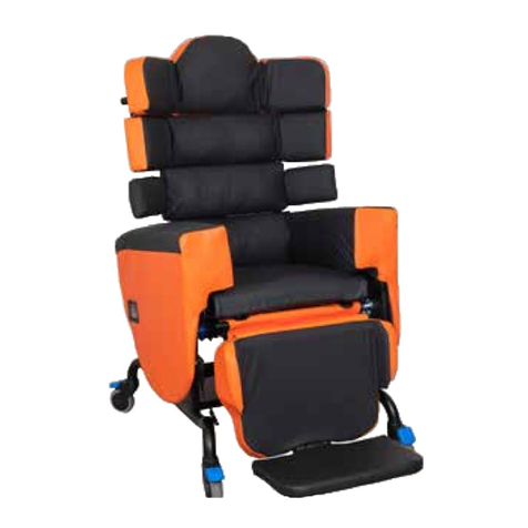
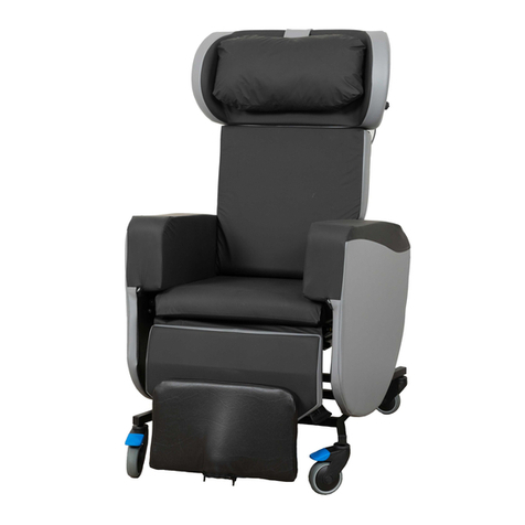
The SmartSeat chair is designed for a range of clients who require a combination
of comfort, pressure management and posture control from their seating system.
The chair has a built-in pressure management system based on CareFlex’s patented
WaterCell Technology®.
The adjustability of the chair and the range of complementary accessories mean
that the chair is suitable for clients who require specific support and positioning to
achieve a good posture. The chair can be used in single or multi-user environments.
The SmartSeat chair should be selected for clients:
• Who need to maintain a reasonable, midline posture.
•With neurological conditions which make them sensitive to discomfort or affect .
muscle tone so that support is required to combat fatigue.
• For whom seat height for transfer is critical.
•When posture, pressure and comfort are important in equal measure.
•Who require a wide range of positions for different activities through the day.
The SmartSeat chair should also be considered:
•For multi-user environments such as stroke wards.
•Where infection control is an issue.
The SmartSeat chair is all about keeping the client in a functional position which is
also comfortable and minimizes the risk of soft tissue damage. Once set up, the
support will accommodate a range of postures.
The SmartSeat chair is suitable for clients who have or are:
•Congenital conditions e.g. Cerebral Palsy
•Neurological conditions e.g. MS, MD, MND
•Lower limb amputation
•Early stage HD
•Recovering from a Stroke or have long terms effects of a stroke
•Learning difficulties
• Frail and/or elderly

UI SmartSeat iss01, 03/2013
5
SmartSeat Unique Features
The SmartSeat chair incorporates features which allow it to be set up to
accommodate different postures and provide seating positions for a range of
activities. The key features are:
•Tilt-in-Space, which allows the client’s position to be adjusted without affecting
pelvic position.
• Legrest elevation, to raise the legs and support the lower leg with the knees at a
relaxed angle.
Pressure Relief and Support Features
CareFlex’s Unique WaterCell Technology®
The SmartSeat chair incorporates CareFlex’s patented WaterCell Technology®in
the seat in combination with a composite visco elastic memory foam and high elastic
foam cushion. The memory foam allows the seat cushion to conform to the client’s
body shape, distributing their weight over as large a surface area as possible. The
high elastic foam prevents the memory foam bottoming out and makes the cushion
responsive to client movement. The WaterCell Technology moves with the client
to ensure that the cushion remains in contact with the client as they move and alter
their weight distribution.
These pressure relief features make the SmartSeat chair suitable for those
clients at medium to high risk of pressure damage when used as part of a
therapy programme assessed and prescribed by an appropriate Healthcare
Professional.
Back Support Options
Two back support options are available for the SmartSeat chair. The deep laterally
contoured back has kidney pads to provide simple lateral stability. These pads also
increase the contact surface between client and seat, distributing their weight over
as large a surface area as possible. The flat back has a basic lumbar curve and allows
for the use of the SmartSeat adjustable laterals accessory which provides more solid
prescriptive support to the thorax.

SmartSeat
®
UI SmartSeat iss01, 03/2013
TM
6
Choice of Actuation Formats
The SmartSeat chair has two actuation formats; manual, and motorised.
1. Manual Format
On the manual version of the SmartSeat chair Tilt-in-Space and the elevating legrest
are controlled by locking gas actions.
2. Motorised Format
On the motorised version of the SmartSeat chair the Tilt-in-Space and the elevating
legrest are controlled by electric actuators which are powered by a rechargeable 24V
battery system.
Maintenance and Servicing
All the covers on the SmartSeat chair can be removed for maintenance and
servicing. No hook and loop fastenings or staples are used externally on the
upholstery of the chair, making cleaning easier and addressing the majority of
infection control issues.
Each SmartSeat chair has a unique chair number which must be quoted during any
correspondence with CareFlex or your local CareFlex Distributor. This number is on
a silver foil label on the right hand side plate at the bottom of the back frame, above
the seat depth adjustment rail at the back of the chair. The number is essential for
tracing the product and allows accessories and spare parts to be easily selected.
Set-up and Adjustment Top Tips
Use a cloth tape measure to measure the client as you are setting up the chair.
This will help limit the need for any re-adjustment. Regularly check the SmartSeat
set up to ensure it is working as intended and the client is benefiting from the
posture and pressure management solutions which are built into the chair.

UI SmartSeat iss01, 03/2013
7
Chair Set-up
Importance of Chair Set-up
The suitability and effectiveness of these
features are dependent on correct chair set
up. Correct chair set up is dependent on three
key elements: seat depth, seat width and seat
to floor/footrest height.
Seat Depth
Seat depth and width must be set up to suit the
client once the chair has been delivered.
Seat to Footplate Height
Seat to footplate height can be adjusted to suit
the client and is likely to be adjusted regularly.
Seat to Floor Height
Seat to floor height will have been measured
during the initial seating assessment and
the SmartSeat chair will have been factory
assembled to these measurements but can be
adjusted by a technician in the field.
Seat Depth
It is important to set seat depth correctly in
order to prevent ‘sacral sitting’ and to achieve
the best distribution of weight between the
client and the chair. Sacral sitting occurs when
the pelvis tilts backwards so that the lower
back (sacrum), as well as the bottom, is resting
on the seat cushion. The sacral area can be
susceptible to pressure problems. Sacral
sitting will occur if the seat depth is too long.
If the seat depth is too short then the client’s
SAFETY NOTE
Seat depth should not be adjusted when a client is sat in the chair or
when the chair is tilted backwards.
Seat Too Short;
Increase in pressure
beneath the bottom.
Seat Too Long;
Increased pressure on
bottom, sacrum and
shoulders.

SmartSeat
®
UI SmartSeat iss01, 03/2013
TM
body weight will be concentrated in too small
an area.
Seat depth should be set with the client’s
bottom positioned firmly at the back of the
seat cushion so that their lower back and
lumbar is supported by the back cushion.
There needs to be a two or three finger gap
between the client’s calf and the front of the
seat cushion for comfort.
If the client already has a chair or wheelchair
with the correct seat depth, measure this size
and use it to set up the SmartSeat chair.
Adjusting Seat Depth:
1. Seat depth is adjusted by moving the back
of the chair over the seat unit. The front edge
of the seat will stay in the same place. The seat
depth mechanism is controlled by a release
lever on the rear left hand underside of
the seat.
2. To adjust seat depth, locate the two rails
at the bottom of the back valance. Squeeze
the thinner rail up against the thicker rail to
release the mechanism controlling seat depth.
Keeping the two rails squeezed together, push
or pull the back of the chair to the desired
position. Once at the correct position, release
the lower, thinner rail. The back may jump back
slightly as the locking mechanism engages.
8
Squeeze the thin rail against the thicker rail to
release the seat depth mechanism.

UI SmartSeat iss01, 03/2013
Seat Width
Seat width affects side-to-side pelvic stability.
This is important as the spine should line up
centrally with the pelvis. If the pelvis is free
to move to one side then the client’s spine
will usually lean in the opposite direction. As
gravity pulls the client over, the spine will begin
to curve to compensate as the client tries to
keep their head level. The client will take on
a characteristic ‘S’ shaped spine or scoliosis.
The more upright the user’s trunk is, the more
critical pelvic stability becomes. It is, therefore,
important to use a chair with the correct seat
width in order to position the pelvis properly.
Seat width should always allow for a little bit
of movement as the client’s body weight and
posture naturally shifts throughout the day.
If the client is held in a rigid position, they will
quickly tire and experience discomfort.
Adjusting Seat Width:
1. Each arm of the SmartSeat has a unique
adjustment mechanism which allows the arm
to be moved in or out relative to the centre of
the chair.
2. To release the mechanisms, locate the
tabs on the back of the arms. Pull the tabs
backwards until they stop. To reduce seat
width, by moving the arms in towards the
centre of the chair, place the palm of your hand
in the middle of the outside face of the arm
and push the arm inwards. To increase seat
width by moving the arms out from the centre
of the chair, place your hand in the middle of
the arm against the inside face and pull the
arm outwards.
9
Correct seat width;
client sits ‘midline’.
Seat Too Wide; client
tends to lean to one
side.
Pull the tabs on the back of the arms to
release the mechanism to adjust seat width.
Pull the tab out and push the middle of the
arm to reduce the seat width.

SmartSeat
®
UI SmartSeat iss01, 03/2013
TM
3. Once the arm is in the desired position let
go of the tab. The arm may jump slightly as the
adjustment mechanism locks into the most
appropriate position. If the chair is unoccupied,
smooth out the lumbar cushion to minimize
wrinkling of the cover.
Checking Symmetry of Seat Width
Wherever possible aim to have the arms
adjusted symmetrically so that the client
is located centrally in the chair. Look at the
arms from the back of the chair and judge
distance from the inside face of arms to the
edges of the chair back frame. For the most
accurate set-up of seat width, use a rule or
tape measure or the incremental markings on
the back of these instructions to ensure the
adjustment of the arms is symmetrical.
10
SAFETY NOTE
Do not adjust seat width if the
occupant is leaning heavily onto the
arm you are trying to adjust. Do not
attempt to adjust seat width when the
tray accessory is fitted to the chair.
Pull the tab out and pull the middle of the arm
to increase the seat width.
Use a tape measure, rule or the guidelines on
the back page of these instructions to check
arm position and symmetry.

UI SmartSeat iss01, 03/2013
Seat Height
If the client can raise to standing themselves or
with minimal assistance, the seat height should
be set so that the client’s feet rest flat on the
floor and the underside of their thighs are in
contact with the full length of the seat cushion.
If the seat height is too high, the client’s heels
will be lifted off the floor and pressure will build
up along the underside of their thighs. If the
seat is too low, their knees will be raised and
there will be no contact between the back
of their thighs and the seat cushion. This will
increase the pressure on their bottom and
sacrum and could cause discomfort at the
hips.
If the client is less ambulant and is being
regularly portered then seat height can be set
relative to the footplate. Again, ensuring the
foot is flat and fully supported is important.
The SmartSeat chair seat height will have been
measured during assessment and the chair
made to these dimensions for the client prior
to delivery.
Further Adjustments
If further adjustment is required, please
contact your local CareFlex Distributor or
contact CareFlex for the additional ‘SmartSeat
Chair Seat Height Adjustment’ User
Instruction document.
11
Seat Too Low;
Increase in pressure on
the buttocks and lower
back.
Seat Too High;
Increase in pressure
beneath thighs.

SmartSeat
®
UI SmartSeat iss01, 03/2013
TM
Brakes
During transfer it is important that the chair
is as stable as possible. The chair is fitted with
four fully braked castors and the brakes on at
least two castors should be engaged before
transfer.
Locking the Brakes:
1. To lock the brakes, position the chair
approximately where you need it to be for
transfer. Gently push the chair away from you
so that the castors swivel around so that the
blue brake levers can be easily accessed.
2. Press down the end of the blue brake levers
with your foot. The lever will angle down and
click into the locked position.
Releasing the Brakes
To release the brakes, gently kick the end of
the lever which is pointing upwards. The lever
will snap down and the castors will roll freely.
Tilt-in-Space
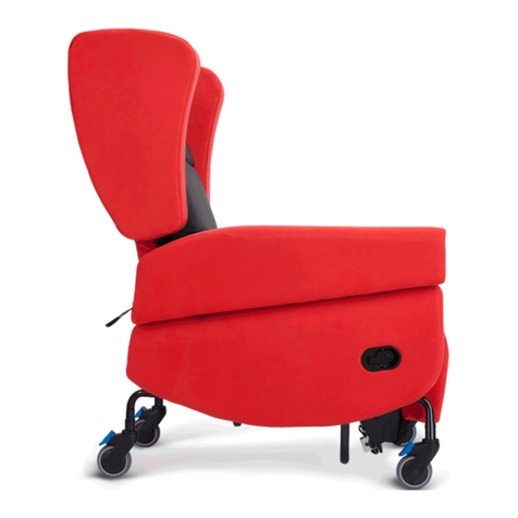
The SmartSeat chair has a Tilt-in-Space facility
which allows the client to be reclined without
adjusting the angle at the hips. This helps the
client to maintain a stable sitting posture whilst
distributing their weight over a large surface
area.
12
The SmartSeat Chair in Day to Day Use
Each castor has a brake.
Apply at least two before transfer.
SAFETY NOTE
When tilting the SmartSeat chair forward,
ensure the footplate height is set so that the
footplate will not hit the floor.

UI SmartSeat iss01, 03/2013
Tilt-in-Space should be regularly adjusted to
facilitate an easy change in weight distribution,
thus avoiding pressure build up in any one area.
Always warn the client before changing Tilt-
in-Space to ensure they do not become
distressed or agitated.
The chair will Tilt-in-Space 20°backwards. This
degree of tilt may be disconcerting for some
clients. Please ensure the client is comfortable
and does not become distressed if they are
fully tilted backwards.
Adjusting Tilt-in-Space:
1. Manual Format
On the manual option the Tilt-in-Space feature
is controlled by the large lever on the push
handle.
To adjust the Tilt-in-Space, squeeze the lever
and tilt the chair to the desired angle. Release
the lever to hold the chair at the desired angle.
2. Motorised Format
On motorised chairs, the second row of
buttons on the handset control the Tilt-in-
Space movement.
SAFETY NOTE
It is essential to regularly check the adjustment
of the seat to footplate height to ensure it does
not hit the ground when lowered. When the chair
is tilted backwards it is possible to extend the
seat to footplate height so that it is greater than
the seat to floor height. However, if the chair is
tilted forward when the seat to footplate height
is fully extended the footplate may hit the floor
and damage the legrest mechanism. This is
especially important if the chair is in its lowest
seat to floor height setting.
13

SmartSeat
®
UI SmartSeat iss01, 03/2013
TM
Legrest Elevation
The SmartSeat chair has an integral legrest
which can be angled upwards to support
the legs. The patented legrest mechanism
articulates, following the movement of the
knee as it elevates the legs. The legrest
incorporates visco-elastic memory foam for
pressure relief.
Ensure the legrest is fully lowered before
transferring a client to or from the chair.
The range of legrest elevation is from 80° at
the knees to 170°. Over-elevating the legs can
cause tightness in the hamstrings which could
cause discomfort. A legrest cannot be used
to ‘straighten’ contractures in the knees and
close attention needs to be paid to the angle
of elevation and for how long legs are elevated
to ensure good positioning and continued
comfort.
Adjusting Legrest Elevation:
1. Manual Format
On the manual option of the SmartSeat chair,
legrest elevation is controlled by the lever
located on the right hand side panel. Pull this
lever out and the legrest will begin to raise. It
may be necessary to lift the legrest towards its
maximum elevation, depending on the
weight of the client’s lower legs. Once the
legrest is at the desired angle, release the lever.
To lower the legrest, pull the lever out and the
legrest will return to its lowered position. It may
be necessary to push the legrest down if the
client has weak or light lower legs.
14
Manual operation legrest lever on the right
side of the chair.

UI SmartSeat iss01, 03/2013
15
2. Motorised Format
On the motorised option, legrest elevation
is controlled by the handset. The top row of
two buttons control legrest elevation. The
left hand button raises the legrest. The right
hand button returns the legrest to its lowered
position.
Integral Footplate
The legrest has an integral height and angle
adjustable footplate to provide support to
the client’s feet when the legrest is raised or
when they are being portered in the chair. The
footplate is stowed away behind the legrest.
Accessing the Footplate
Tilting the chair back and elevating the legrest
gives better access for deploying the footplate.
The first few times the footplate is used it
will be easier to position the chair like this so
that familiarity with the process can be easily
developed.
Deploying the Footplate:
1. To deploy the footplate look for the front
edge of the footplate sticking out from the
bottom of the legrest. Locate the release
handle centrally located at the back of the
footplate. Twist the handle out and the
footplate will drop forward. Grip the recess on
the front edge of the footplate and pull the
footplate out. Continue to pull the footplate
until it is felt to click into its locked, 90° position.
2. At this point the footplate will look short.
A further tug on the front edge of the
footplate extends the support surface. At full
extension the foot support surface should be
approximately 26cm from front to back.
central release handle to deploy the footplate
Grip the centre of the footplate to extend the
foot support surface.

SmartSeat
®
UI SmartSeat iss01, 03/2013
TM
Footplate Angle / Plantar Flexion Control
The footplate has three angle settings to
provide comfort and support plantar flexion.
As the legrest is elevated, having a 90° angle
at the ankle will become more uncomfortable.
The footplate can be angled down to provide a
more relaxed position.
Adjusting Footplate Angle
To adjust the angle, locate the round knobs
mounted each side of the back corners of
the footplate. Pull out the knobs and tilt the
footplate to the desired angle. Release the
knobs and they will click into the nearest angle
setting.
Stowing the Footplate:
1. To fold the footplate up and store it behind
the legrest the legrest must be set at its 90°
angle position. See ‘Footplate Angle / Plantar
Flexion Control’ for instructions on how to do
this.
2. Once the footplate angle is at 90°, give the
front edge of the footplate a sharp tap and
push the footplate in to its minimum depth.
3. Reach under the footplate and locate the
release handle. Pull this out and the footplate
will start to drop back. Keep pushing the front
edge of the footplate and it will swing up
behind the legrest. A further sharp push at the
end of the movement will lock the footplate in
its stowed position.
16
Pull out the round knob on each side of the
back edge of the footplate to adjust footplate
angle
Pull out the release handle to get the
footplate to drop back behind the legrest for
stowing

UI SmartSeat iss01, 03/2013
Seat to Footplate Height
The SmartSeat chair has an articulating legrest
which has a naturalistic movement to provide
support to the lower leg as the knees flex. This
means that for the majority of occupants the
footplate will provide consistent support as
the legrest elevates. However, it is sometimes
necessary to make seat to footplate height
adjustments as a consequence of knee
position not working in harmony with the
action of the legrest.
Adjusting Seat to Footplate Height:
1. To adjust seat to footplate height, deploy
the footplate and locate the indexer on the
footplate receiver mounted centrally on the
back of the legrest.
2. Pull the indexer out and lift/lower the
footplate to the desired position. Once at
the desired position, release the indexer. The
footplate may drop slightly as the indexer
locates in the closest height setting.
Footplate Removal and Re-fitting
At some point the footplate may not be
required. The footplate can be removed if this
is the case.
Removing the Footplate
To remove the footplate, stand at the right
side of the chair and elevate the legrest to
maximum. Locate the indexer controlling seat
to footplate height, pull it out and at the same
time pull the footplate out until you feel it hit
its maximum stop. On the right side of the
indexer, feel for a small round button. Press
this in and the footplate assembly will slide free
of the receiver on the legrest. Be prepared to
take the weight of the footplate assembly as it
comes free of the legrest.
17
Indexer for seat to footplate height
adjustment
Retaining button. Press in to slide footplate
out completely.

SmartSeat
®
UI SmartSeat iss01, 03/2013
TM
Re-fitting the Footplate
To re-fit the footplate assembly, present
the rectangular tube of the assembly to the
receiver on the back of the legrest. Push in the
small button on the top edge of the tube so
that it can slide into the receiver. Adjust the
footplate to the desired height.
SmartSeat Arms
Arm Removal and Side Transfer
The arms of the SmartSeat chair can be
removed for servicing and for side transfer. If
the intention is to regularly remove the arms
then the arm location locking device can be
disabled so that the arms can be lifted off the
chair easily.
Occasional Arm Removal:
1. Detach the tabs which hold down the front
edge of the seat cushion. Plastic ‘J’ strips are
sewn onto the ends of these tabs and clip on
to thin round bars on the underside of the front
edge of the seat board.
2. Push the front of the cushion to one side
to reveal the side cover attachment. Unclip
the ‘J’ strip at the front top corner of the side
cover. Hold the cover up and locate the vertical
tube which is the front location point for the
arm. At the end of the tube you will see a small
round button. This is the locking device which
prevents the arm being inadvertently removed
from the chair. Press this button in to the tube
and lift the arm clear of the chair. You may
need to angle the arm outwards to clear the
underside of the wing if seat depth is adjusted
towards the minimum setting.
18
Front location point for arm fitment.
Depress the button to release the front arm
mounting peg

UI SmartSeat iss01, 03/2013
3. Re-fit the arm by reversing the above
process.
Frequent Arm Removal:
1. If the arm is going to be removed frequently,
as would be expected if regular side transfers
are being made, the locking device can be
disabled. To do this you will need a pair of long-
nosed pliers. This should not be done to chairs
in multi-user environments or where people
with challenging behaviour may unintentionally
remove the arm.
2. Remove the arm as described above. With
the arm off the chair, depress the small round
button of the locking device into the front arm
mounting peg. Take a pair of long-nosed pliers
and whilst holding the small button down, push
the pliers up into the bottom end of the tube.
This will push the small button past its locating
hole and prevent it popping out and disabling
the locking device.
3. To reinstate the locking device, use long-
nosed pliers to carefully grip the end of the
small button and pull and twist it around so that
it pops back through its locating hole.
19
Lift the arm off the base sides
If arms are beiong frequently removed, the
button in the mounting peg needs to be
depressed and then pushed up into the tube

SmartSeat
®
UI SmartSeat iss01, 03/2013
TM
Accessories and Options
Contoured Back
As with all CareFlex chairs, a contoured back
option is available which offers simple lateral
support, helping to limit leaning and give
additional control during upper
trunk movement.
When ordered as an option on a new chair
the Contoured back consists of a medium
density foam profile which has sculpted sides
to provide support to the sides of the ribcage.
This support is in place above arm height as
the seat width adjustment system allows for
accurate control of lateral hip position.
Retro-fitting Contoured Back
A contoured back can be fitted to a chair
which was originally ordered with a flat
back. A replacement or retro-fit contoured
back consists of the profiled foam and an
appropriately shaped cover.
Fitting Instructions:
1. To fit a contoured back you will need a
13mm spanner or socket wrench. Begin by
unclipping the sides of the chair back valance.
There are plastic ‘J’ strips sewn to the edges
of the valance. These clip over thin bars which
make up part of the structure of the chair back.
Starting at the lower sides, unclip the valance
until it can be folded over the top of the chair
back.
2. Detaching the valance reveals the three
back cushion frames. Identify the middle frame
and look for the nuts in each corner which hold
the frame in place. Undo the nuts and keep
them safe, ready to re-fit the frame.
20
Grip the J strip at the top and un-clip from the
thin side bar
Continue around the bottom edge of the
valance.
Remove the flange nut at each corner of the
middle cushion wire to remove the middle
cushion.
Table of contents
Other CareFlex Indoor Furnishing manuals
Popular Indoor Furnishing manuals by other brands

RTA Products
RTA Products Techni Mobili RTA-KS40C Assembly instructions

Argos
Argos 833/0325 Assembly instructions

Seconique
Seconique Corona 2 Door 1 Drawer Wardrobe Assembly instructions

Astonica
Astonica 50104289 instruction manual

LDI Spaces
LDI Spaces Safco 5260 Assembly instructions

Wilkhahn
Wilkhahn ON. quick start guide

bbf
bbf 2954ACS Assembly guide

Flexsteel home
Flexsteel home Power Recliner with Power Headrest and... manual

storke
storke Nero installation guide

AutoMotionShade
AutoMotionShade 4280P-1230 Quick reference guide

highwood
highwood Lehigh AD-KITBALC101-ACE Assembly guide

Zinger
Zinger ZR-10 User manual and warranty