CareFlex SmartSeat Small Guide

UI SmartSeat seat height supplemental iss02, 07/2014
The CareFlex SmartSeat
Seat Height Adjustment
CareFlexibility
Class 1
Medical Device
TM
TM
SmartSeat
®
UI SmartSeat seat height supplemental iss02, 07/2014
TM
These are the user instructions for
adjusting seat to floor height on the
SmartSeat specialist seating system
from CareFlex. Please read them carefully
before using the chair and keep
them in a safe place for future reference.
Adjusting seat to floor height is simple
but needs to be carried out by someone
who has confidence in their mechanical
skills and who is happy using basic hand
tools such as spanners and screwdrivers.
To adjust seat to floor height you will
need;
• Socket wrench with 13mm socket
• 13mm spanner
• 17mm spanner
• Set of Allen keys
• Cross-head screwdriver
2
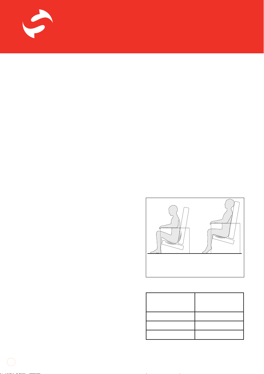
Seat Height
If the client can raise to standing
themselves or with minimal assistance,
the seat height should be set so that the
client’s feet rest flat on the floor and the
underside of their thighs are in contact with
the full length of the seat cushion. If the
seat height is too high, the client’s heels will
be lifted off the floor and pressure will build
up along the underside of their thighs. If the
seat is too low, their knees will be raised and
there will be no contact between the back
of their thighs and the seat cushion. This
will increase the pressure on their bottom
and sacrum and could cause discomfort at
the hips.
Each size of chair has three seat to floor
height settings as per the table.
Seat Too Low;
Increase in pressure on
the buttocks and lower
back.
Seat Too High;
Increase in pressure
beneath thighs.
Small
SmartSeat
Medium
SmartSeat
45cm, low set 54cm, low set
48cm, mid set 57cm, mid set
51cm, top set 60cm, top set

UI SmartSeat seat height supplemental iss02, 07/2014
3
Adjusting seat height takes approximately
15 minutes. The chair can be adjusted
one side at a time but both sides must be
adjusted to the same height before the
chair is used.
Begin the process by tilting the chair
forward into its upright position. Do not
adjust tilt again as this will cause the gas
action or motor to over extend, which will
make re-fitting exceptionally difficult.
Locate the Tilt-in-Space (TiS) interface
bracket on the back cross bar of the castor
frame. The bracket is held in place with two
bolts.
Use a 5mm allen key and a 13mm spanner
to undo the two bolts holding the interface
bracket in place and carefully lower the Tilt
action to rest on the floor. Put the bolts and
nuts in a safe place ready for re-fitting at
the end of the height adjustment process.
Remove both of the chair arms as per the
main SmartSeat user instructions.
Undo the zip holding the two halves of
the crumb catcher between the seat and
legrest.
Remove the seat cushion by un-clipping
the J-strip on the underside front edge of
the seat cushion and on the flap at the back
of the seat cushion.
Disconnect the TiS interface bracket first.
Undo the crumb catcher zip and remove the seat
cushion.
Unclip the J-strip on the small cover panel to the
front top edge.
SmartSeat
®
UI SmartSeat seat height supplemental iss02, 07/2014
TM
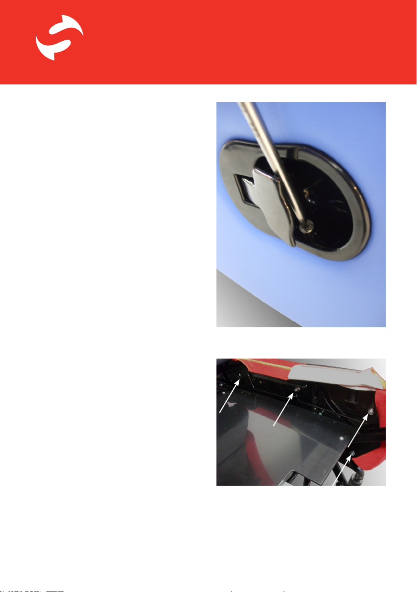
When adjusting a manual chair, undo the
screws which hold the legrest release
lever in place on the right side of the chair.
Use a cross-head screwdriver to undo the
screws and carefully pull the lever out of its
aperture. Do not disconnect the cable.
The front inner top edge of the side panels
have a small cover panel which clips over a
wire on each side of the seat board. Un-clip
the J-strip from this wire to reveal the nuts
which hold the side panels in place.
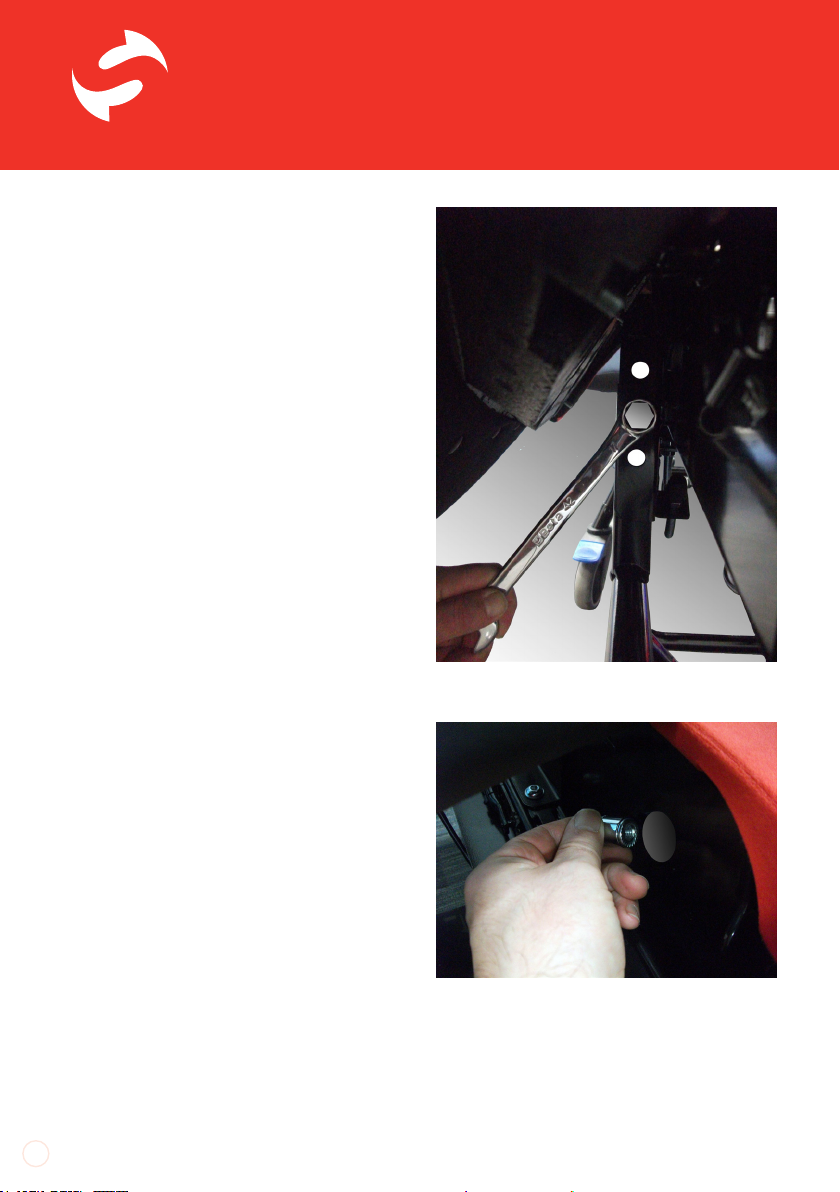
Undo each of these nuts using a socket
wrench with a 13mm socket. There are five
nuts each side and the two rear nuts can
be obscured by the sides of the back frame
depending on the seat depth adjustment of
the chair.
Adjust the seat depth so that all five nuts
from each side can be accessed and
removed. Keep the nuts in a safe place for
future re-fitting.
The side panels are now only held in place
by the arm fitment trim plates and care
needs to be taken not to attempt to move
the chair by pulling the side panels. Handle
the side panels very gently to avoid damage
to the covers.
Carefully angle the side panel out to give
access to the height adjustment points on
the frame.
Locate the 4 nuts in front of the chair back.
Undo the top and bottom screws holding the
legrest release lever.

UI SmartSeat seat height supplemental iss02, 07/2014
The seat to oor height of the chair is
controlled by an adjustment point on either
side of the chair where the castor frame
attaches to the pivot plates of the seat
frame.
The pivot plates have height settings on the
front and back edges. Bolts are fastened
through the height settings on the front
and back edges into screw tments on the
castor frame to set seat height.
The bottom hole is the top seat height
setting, the middle the mid-point setting
and the top hole is the bottom setting. See
the table on page 2 for dimensions for each
seat height on the appropriate size chair.
Work on one side of the chair at a time.
Carefully lift up a side panel and use a 17mm
spanner to undo the bolts controlling seat
height.
Raise or lower the pivot plate so that the
bolts can be re-tted back through the
appropriate height setting holes and in to
the tments on the castor frame.
Ensure the bolts on both front and back
edges are fully tightened before dropping
the side panel back down into place.
Locate the nut towards the back of the chair and
use a socket wrench to undo it.
Carefully angle the side panel out to access the
height adjustment points.
Use a 17mm spanner to undo the height bolt on
the front edge looking from the front of the chair.
low set
mid set
top set
SmartSeat
®
UI SmartSeat seat height supplemental iss02, 07/2014
TM
6
Repeat the procedure for the other side
of the chair, making sure that the height
setting is the same on either side of the
chair before re-tting the side panels.
To re-position the side panels use the nuts
which were removed earlier.
To t the nuts onto the threaded stems of
the side panels, use a 13mm socket to hold
each nut as it is turned into position on a
thread. This makes tting the two rear nuts
easier.
Tighten the nuts nger tight before
tightening them a further half turn with
a spanner or socket wrench. Only three
to four threads should protrude from the
end of the nut to ensure they are not over
tightened.
Over tightening the nuts will damage the
side panels and cause interference with the
seat depth mechanism, especially on the
small chair.
On manual chairs, re-t the legrest release
lever into the aperture on the right base
side panel. Push the lever in rmly, making
sure the lever overlaps the cover all the way
around. Re-t the two screws which hold
the legrest lever in place, taking care not
to over-tighten them as this may strip the
thread which holds them in place. Hold the nuts in a 13mm socket to make fitment
onto the studs of the side panel easier.
Use a 17mm spanner to undo the height bolt on
the back edge looking from the rear of the chair.
low set
mid set
top set

UI SmartSeat seat height supplemental iss02, 07/2014
If the covers of the side panels pull away
from under the arm mounting trim plates,
loosen the screws holding the trim plates in
position and tuck the edge of the cover back
under the trim plate.
Re-tighten the trim plate screws to hold the
cover neatly in position.
Once the main adjustment has been made
at the sides of the chair the TiS control
needs to be re-tted at the appropriate
height setting.
There are three height settings into which
the interfacing bracket can be tted
consisting of two holes. The bottom two
holes correspond with the lowest height
setting, the middle two holes the mid-point
setting and the top two holes the highest
setting.
It is essential that the interface bracket is
tted between the correct holes. Never
attempt to re-position the interface bracket
in an attempt to increase or decrease the
range of Tilt-in-Space.
Position the interface bracket in the main
bracket on the frame crossbar and line up
the appropriate set of holes.
Re-t the bolts removed earlier through the
assembly and fasten them in place with the
nyloc nuts. Use a 5mm allen key and 13mm
spanner to ensure the assembly is fully
tightened.
If necessary, loosen off the arm mounting
point trim panels to ensure the cover is trapped
securely in position.
Re-fit the TiS interface bracket into the
appropriate holes on the bracket on the castor
frame crossbar.
low set
mid set
top set

8
To nd out more or to book a free, no-obligation product demonstration please:
Call: 0800 0186440 | Email: enquiries@careex.co.uk | Visit: www.careex.co.uk
This manual suits for next models
1
Other CareFlex Indoor Furnishing manuals


Popular Indoor Furnishing manuals by other brands


Coaster
Coaster 4799N Assembly instructions

Stor-It-All
Stor-It-All WS39MP Assembly/installation instructions

Lexicon
Lexicon 194840161868 Assembly instruction

Next
Next AMELIA NEW 462947 Assembly instructions

impekk
impekk Manual II Assembly And Instructions

Elements
Elements Ember Nightstand CEB700NSE Assembly instructions


