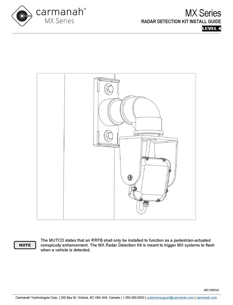
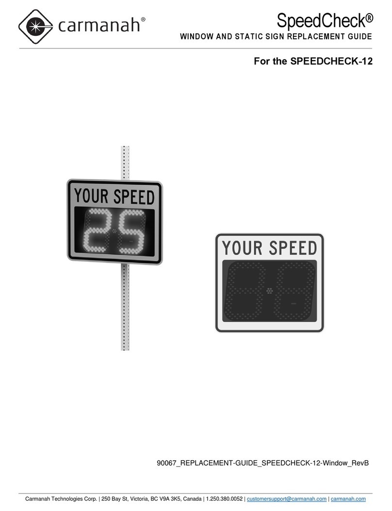
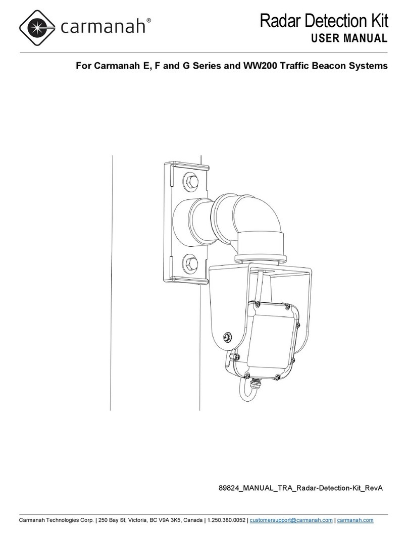
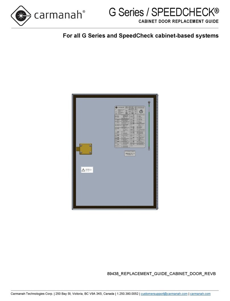
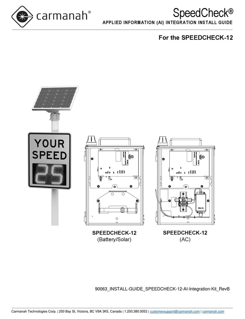
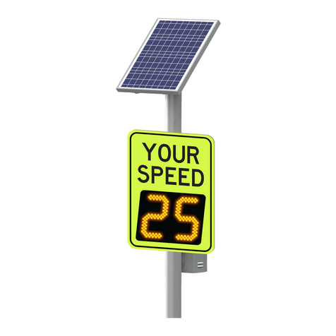
Carmanah SPEEDCHECK Series User manual

Carmanah Technologies Corp. | 250 Bay St, Victoria, BC V9A 3K5, Canada | 1.250.380.0052 | customerservice@carmanah.com | carmanah.com 2
SPEEDCHECK-15/18 USER MANUAL
1.0 INTRODUCTION
Table of Contents
1.0 Introduction.........................................................................................................................................................4
1.1 Warranty Disclaimer ...................................................................................................................................4
1.2 Standards ...................................................................................................................................................4
1.3 Safety and Usage Precautions...................................................................................................................5
1.4 System Components ..................................................................................................................................6
2.0 System Overview................................................................................................................................................7
2.1 SpeedCheck-15/18 Display Sign Enclosure Dimensions...........................................................................7
2.2 Typical Configurations –Overview.............................................................................................................8
2.3 Typical Configurations –SpeedCheck-15 with AC Power routed to sign ..................................................9
2.4 Typical Configurations –SpeedCheck-15/18 with Solar Power from Cabinet........................................ 10
2.5 Typical Configurations –SpeedCheck-15/18 with AC Power from Cabinet............................................ 11
2.6 Typical Configurations –SpeedCheck-15/18 –External Beacons.......................................................... 12
3.0 Components and Preparation ........................................................................................................................ 13
3.1 Components Supplied ............................................................................................................................. 13
3.2 Other Components Required................................................................................................................... 13
3.3 Tools Required ........................................................................................................................................ 14
3.4 Banding Recommendations .................................................................................................................... 14
3.5 Overview of Cabinet Connection Terminals............................................................................................ 15
3.6 SpeedCheck Controller –Input and Output Connections ....................................................................... 16
4.0 Installation........................................................................................................................................................ 17
4.1 Pole Preparation...................................................................................................................................... 17
4.2 Round Pole Installation............................................................................................................................ 18
4.3 Flat Surface Mount Installation................................................................................................................ 19
4.4 Quick Change Pole Mount....................................................................................................................... 20
4.5 Tilt Mount................................................................................................................................................. 21
4.6 Cabinet Installation .................................................................................................................................. 22
4.7 Solar Panel Mount Installation................................................................................................................. 23
4.8 Solar Power System Wiring..................................................................................................................... 27
4.9 Circular Beacon Installation..................................................................................................................... 28
5.0 Display Alignment ........................................................................................................................................... 29
5.1 Display Alignment –Overview................................................................................................................. 29
5.2 Display Alignment –Hill Alignment.......................................................................................................... 31
5.3 Display Alignment –Curve Alignment..................................................................................................... 33
5.4 Display Alignment –Rotational Display Sign Alignment ......................................................................... 34
Carmanah Technologies Corp. | 250 Bay St, Victoria, BC V9A 3K5, Canada | 1.250.380.0052 | customerservice@carmanah.com | carmanah.com 3
SPEEDCHECK-15/18 USER MANUAL
1.0 INTRODUCTION
6.0 Commissioning Checklist............................................................................................................................... 35
7.0 Maintenance and Product Care...................................................................................................................... 36
7.1 Sign Inspection ........................................................................................................................................ 36
7.2 Battery Replacement (Solar-Powered System)....................................................................................... 37
7.3 Internal Components ............................................................................................................................... 37
8.0 Troubleshooting .............................................................................................................................................. 38
9.0 Service & Repair .............................................................................................................................................. 40
9.1 Accessing Internal Components.............................................................................................................. 40
9.2 Accessing SpeedCheck-15 Display Boards............................................................................................ 41
9.3 Releasing Locking Features.................................................................................................................... 42
9.4 Removing Display Boards ....................................................................................................................... 43
9.5 SpeedCheck Controller Cable Connections (Legacy)............................................................................. 44
9.6 SpeedCheck Controller Cable Connections (Legacy –without Slow Down) .......................................... 44
9.7 Programmable Board Display Cable Connections (with Slow Down) ..................................................... 45
10.0 Customer Service and Warranty.................................................................................................................. 46

Carmanah Technologies Corp. | 250 Bay St, Victoria, BC V9A 3K5, Canada | 1.250.380.0052 | customerservice@carmanah.com | carmanah.com 4
SPEEDCHECK-15/18 USER MANUAL
1.0 INTRODUCTION
1.0 Introduction
The following symbols indicate important safety warnings and precautions throughout this manual:
WARNING indicates that serious bodily harm or death may result from failure to adhere to the
precautions.
CAUTION indicates that damage to equipment may result if the instructions are not followed.
NOTE suggests optimal conditions and provides additional information.
1.1 Warranty Disclaimer
This manual will familiarize you with the features, operation standards, and installation of Carmanah’s
SpeedCheck-15/18 radar speed sign. Failure to comply with the use, storage, maintenance, installation or
placement instructions detailed in this manual could void the warranty.
1.2 Standards
Perform all installation, wiring, grounding and maintenance in conformance with local building and electrical
codes. Adherence to the National Electrical Code (NEC) is mandatory to comply with any certification markings.
Non-adherence to code may void the warranty.

Carmanah Technologies Corp. | 250 Bay St, Victoria, BC V9A 3K5, Canada | 1.250.380.0052 | customerservice@carmanah.com | carmanah.com 5
SPEEDCHECK-15/18 USER MANUAL
1.0 INTRODUCTION
1.3 Safety and Usage Precautions
Batteries are shipped fully charged. Use extreme caution when handling the batteries as they can
generate hazardous short-circuit currents. Remove all jewelry (bracelets, metal-strap watches,
etc.) before handling the batteries.
Solar panels produce DC electricity when exposed to light and can therefore produce an
electrical shock or burn. To render solar panels inoperative, remove them from sunlight or fully
cover their front surface with an opaque material.
Before lifting any heavy or bulky equipment, ensure the load is secured so moving parts do not
shift, and that it can be lifted as far as needed without back strain or loss of grip. Installation may
require more than one person.
Ensure the equipment is not powered during installation and wiring of the system.
Recheck all completed wiring for proper polarity prior to energizing the system.
Changes or modifications to Carmanah equipment not expressly approved by Carmanah could
void both the user's authority to operate the equipment and the warranty.
Not all traffic products are compatible with external outputs. Please contact Carmanah for
additional information and guidance when adding or replacing beacons or other hardware.
The electronic equipment used generates, uses, and radiates radio frequency energy, which can
cause radio interference.
The specifications of the products and components described in this manual are subject to
change without notice.

Carmanah Technologies Corp. | 250 Bay St, Victoria, BC V9A 3K5, Canada | 1.250.380.0052 | customerservice@carmanah.com | carmanah.com 6
SPEEDCHECK-15/18 USER MANUAL
1.0 INTRODUCTION
1.4 System Components
Top of Pole Mount
Solar Panels
and Mounts
Side of Pole Mount
Sign
Mounting
Quick Change
(Portable)
Tilt Bracket (for
Vertical Adjustments)
Flat Surface Mount
Standard Mount
(U-bolts or banding)
LED Output
(Beacons or
Strobes)
Radar
Signs
SpeedCheck-15
SpeedCheck-18
Power
System
(Solar or AC)
Solar
Version
AC
Version
Shown with optional
StreetHub™
monitoring

Carmanah Technologies Corp. | 250 Bay St, Victoria, BC V9A 3K5, Canada | 1.250.380.0052 | customerservice@carmanah.com | carmanah.com 7
SPEEDCHECK-15/18 USER MANUAL
2.0 SYSTEM OVERVIEW
2.0 System Overview
2.1 SpeedCheck-15/18 Display Sign Enclosure Dimensions
This manual describes information on the installation, maintenance, troubleshooting, service, and support options
for the SpeedCheck-15 and SpeedCheck-18.
SpeedCheck-15 Display Sign Enclosure Dimensions
SpeedCheck-18 Display Sign Enclosure Dimensions

Carmanah Technologies Corp. | 250 Bay St, Victoria, BC V9A 3K5, Canada | 1.250.380.0052 | customerservice@carmanah.com | carmanah.com 8
SPEEDCHECK-15/18 USER MANUAL
2.0 SYSTEM OVERVIEW
2.2 Typical Configurations –Overview
•SpeedCheck-15 with AC Power routed to sign
- AC input wires connect in junction box
- Optional 12V round LED beacons with internal driver connect in junction box
•SpeedCheck-15 or 18 with Solar/DC battery power in Cabinet
- Coiled up 2 conductor Red/black DC power cable coiled up as it exits the junction box conduit fitting
- Optional 12V round LED beacons with internal driver connect in junction box
- Optional StreetHub™ monitoring available with SpeedCheck-15 only
•SpeedCheck-15 or 18 with AC/DC power supply in cabinet
- Coiled up 2 conductor Red/black DC power cable coiled up as it exits the junction box conduit fitting
- Optional 12V round LED beacons with internal driver connect in junction box
- Optional StreetHub™ monitoring available with SpeedCheck-15 only
Connect to the SpeedCheck sign using a wireless dongle and computer in order to review and
edit system settings. See the separate SpeedCheck Manager software user guide for more
information.
Wireless Dongle
Computer
SpeedCheck Manager
Software User Interface
SpeedCheck Sign

Carmanah Technologies Corp. | 250 Bay St, Victoria, BC V9A 3K5, Canada | 1.250.380.0052 | customerservice@carmanah.com | carmanah.com 9
SPEEDCHECK-15/18 USER MANUAL
2.0 SYSTEM OVERVIEW
2.3 Typical Configurations –SpeedCheck-15 with AC Power routed to sign
Internal AC power supply option not available with SpeedCheck-18.
AC connections are
located inside the
junction box for AC-
in-the-sign version
only.
All other versions
have a power cable
coming out of the
sign.
¾” Liquid-
tight conduit
included
Route AC
power to
enclosure
Drill 1” hole in
pole then seal
appropriately
Recommended 7-10
ft. mounting height

Carmanah Technologies Corp. | 250 Bay St, Victoria, BC V9A 3K5, Canada | 1.250.380.0052 | customerservice@carmanah.com | carmanah.com 10
SPEEDCHECK-15/18 USER MANUAL
2.0 SYSTEM OVERVIEW
2.4 Typical Configurations –SpeedCheck-15/18 with Solar Power from Cabinet
User-
accessible
battery and
solar controller
cabinet
See cabinet drill points
for external conduit
routing
SpeedCheck-18 with alternate
conduit connection point
different from SpeedCheck-15
Optional
StreetHub™
monitoring unit
may be
installed inside
the cabinet
Solar panel
(top of pole
mount)

Carmanah Technologies Corp. | 250 Bay St, Victoria, BC V9A 3K5, Canada | 1.250.380.0052 | customerservice@carmanah.com | carmanah.com 11
SPEEDCHECK-15/18 USER MANUAL
2.0 SYSTEM OVERVIEW
2.5 Typical Configurations –SpeedCheck-15/18 with AC Power from Cabinet
Install
appropriate
pole cap
Route DC supply
harness through
pole
Alternatively,
route external to
pole in conduit
(Conduit and
fittings sold
separately)
SpeedCheck-18
alternate conduit
connection point different
from SpeedCheck-15
See cabinet drill points
for external conduit
routing

Carmanah Technologies Corp. | 250 Bay St, Victoria, BC V9A 3K5, Canada | 1.250.380.0052 | customerservice@carmanah.com | carmanah.com 12
SPEEDCHECK-15/18 USER MANUAL
2.0 SYSTEM OVERVIEW
2.6 Typical Configurations –SpeedCheck-15/18 –External Beacons
Connection points for output harness SpeedCheck-15 can be found in the junction box at the top of the enclosure.
Outputs from the SpeedCheck controller are suitable for powering the input of a round LED beacon that includes
a built in 12V LED driver. See Section 4.9 for more information on circular beacon installation.
To access the SpeedCheck controller, remove
4 screws. Beacon cables are pre-installed if
ordered. Otherwise, install ¾” conduit fitting to
route external 12” round beacons using the
color code shown below (Red positive, black
negative)
SpeedCheck-18 alternate point of
connection for external beacons:
SpeedCheck-15 Junction Box
Beacon cables are factory
installed to terminal block.
Example Circular Beacon Installation

Carmanah Technologies Corp. | 250 Bay St, Victoria, BC V9A 3K5, Canada | 1.250.380.0052 | customerservice@carmanah.com | carmanah.com 13
SPEEDCHECK-15/18 USER MANUAL
3.0 COMPONENTS AND PREPARATION
3.0 Components and Preparation
3.1 Components Supplied
The components below are required to install your SpeedCheck radar speed sign.
Display system:
•SpeedCheck-15 display sign
•Regulatory sign face and mounting brackets (specify during ordering)
•Flexible conduit: 3/4-inch liquid tight (included with display sign)
•Conduit connector (included with display sign)
•Mounting bracket kit (specify during ordering)
•Installation kit (USB dongle for use with SpeedCheck Manager software, alignment kit and foam cone)
•Optional beacons and output harness.
•Optional input harness
Solar-powered systems include these additional components:
•Solar panel
•Solar panel mount (top or side of pole)
•Solar panel harness (available lengths are 8, 16, 36, and 75 ft.)
•Pole-mounted battery box with charge controller, fuses and wiring
•12V non-spillable lead acid battery
•Optional conduit and fittings for routing solar panel harness external to pole (not included)
AC-powered systems include these components:
•Pole-mounted AC Cabinet (for configurations other than SpeedCheck-15 with internal AC power supply)
•Optional conduit and fittings for routing DC input harness external to pole (not included)
3.2 Other Components Required
Review the following items carefully to ensure you have all components required to complete
your installation. If necessary, contact Carmanah for assistance.
The components below are readily available from electrical or traffic control equipment suppliers
•Sign attachment banding and installation tool or heavy-duty tamper proof band clamps
•Appropriate hose clamps for temporary positioning during the sign alignment process before permanently
banding the display sign to the pole

Carmanah Technologies Corp. | 250 Bay St, Victoria, BC V9A 3K5, Canada | 1.250.380.0052 | customerservice@carmanah.com | carmanah.com 14
SPEEDCHECK-15/18 USER MANUAL
3.0 COMPONENTS AND PREPARATION
3.3 Tools Required
The following tools may be required to mount your SpeedCheck radar speed sign, depending on the model and
configuration:
a. Imperial socket set
b. Crescent wrench
c. Tap set
d. Imperial Allen-Wrench set
e. Fish tape
f. Level
g. Compass or pre-determined equatorial
direction
h. Banding installation tool
i. Drill and drill bits
j. Fine tip felt marker
k. Multi-bit screwdriver
l. Pelco Roger-Wrench (signal head beacons)
m. Hook spanner wrench, 1-1/2” trade size
(some configurations)
n. Ladder or lift device
o. Lithium grease
3.4 Banding Recommendations
90 MPH Wind Loading
3/4” x 0.030” band
Single wrap provides adequate strength for 90 MPH wind loading.
5/8” x 0.030” band
Single wrap provides adequate strength for 90 MPH wind loading.
1/2” x 0.030” band
Single wrap provides adequate strength for 90 MPH wind loading.
However, double wrap is preferred on upper mounting bracket to
prevent rotational slippage.
Banding provides the most secure and vandal-resistant mounting. If banding is not available,
U-bolts can be used for most applications.

Carmanah Technologies Corp. | 250 Bay St, Victoria, BC V9A 3K5, Canada | 1.250.380.0052 | customerservice@carmanah.com | carmanah.com 15
SPEEDCHECK-15/18 USER MANUAL
3.0 COMPONENTS AND PREPARATION
3.5 Overview of Cabinet Connection Terminals
Solar Version Connections
AC Version Connections
Solar +
Battery
Connections
StreetHub™
monitoring
device
connections
Display
connects to
DC Output
DC Power
from AC/DC
power supply
(pre-wired)
StreetHub™
monitoring
device
connections
Display
connects to
DC Output

Carmanah Technologies Corp. | 250 Bay St, Victoria, BC V9A 3K5, Canada | 1.250.380.0052 | customerservice@carmanah.com | carmanah.com 16
SPEEDCHECK-15/18 USER MANUAL
3.0 COMPONENTS AND PREPARATION
3.6 SpeedCheck Controller –Input and Output Connections
•Turn off the external source powering the display sign
•Open the fuse block in the display sign
•Wire harness connectors have ramp and clip features to hold the connector in place. If inserting
connectors, ensure the connector ramp engages with the corresponding mating features.
•For more information on the external input options, see the SpeedCheck Manager Software User Guide.
When the input is open, Mode 1 is set. When the input it closed, Mode 2 is set. Route input cables
through the SpeedCheck-15 junction box or SpeedCheck-18 back panel.
•No voltage should be applied to the input connections. The input is activated by shorting the input pins.
THE CONTROLLER CAN BE DAMAGED IF VOLTAGE IS APPLIED TO THE INPUT.
ENSURE THE NOTES ABOVE ARE CAREFULLY REVIEWED BEFORE MAKING ANY
CONNECTIONS. CONTACT CUSTOMER SERVICE IF THERE IS ANY UNCERTAINTY
BEFORE MAKING ANY CONNECTIONS, MODIFICATIONS OR ALTERATIONS.
OUTPUT 1 - RED (+)
OUTPUT 1 - BLACK (-)
OUTPUT 2 - RED (+)
OUTPUT 2 - BLACK (-)
INPUT - GREEN (GND)
INPUT - WHITE (IN)
Connector Ramp
(shown not fully
mated)

Carmanah Technologies Corp. | 250 Bay St, Victoria, BC V9A 3K5, Canada | 1.250.380.0052 | customerservice@carmanah.com | carmanah.com 17
SPEEDCHECK-15/18 USER MANUAL
4.0 INSTALLATION
4.0 Installation
Use hose clamps for the initial setup and alignment of the display sign to determine proper
radar detection of oncoming vehicles. Adjust as necessary before permanently attaching the
display sign to the pole with banding or U-bolts. See Section 5 for proper sign alignment with
respect to the roadway prior to permanently applying banding (for round pole applications).
4.1 Pole Preparation
Ensure the installation location has an unobstructed view of the sun’s path. Obstructions
such as trees or buildings could significantly reduce the amount of sunlight on the solar
panel. Shade analysis is highly recommended to understand how shadows will change
according to the time of year. Contact Carmanah for a detailed examination and solar
simulations for your site.
Ensure proper safety practices are observed and hazardous voltages sources are de-
energized before beginning work.
1. Mark desired positions of cabinet and pole-mounted elements on pole.
2. Drill cable exit/entry points for pole-mounted elements as needed.
3. Route AC input cable to AC power supply (if required).
4. Fish DC harness between power supply cabinet and SpeedCheck sign (if required).
5. Fish solar harness between top of pole to cabinet nipple hole (if required).
6. Fish flashing beacon harnesses between SpeedCheck conduit fittings and flashing beacon holes (if
required).

Carmanah Technologies Corp. | 250 Bay St, Victoria, BC V9A 3K5, Canada | 1.250.380.0052 | customerservice@carmanah.com | carmanah.com 18
SPEEDCHECK-15/18 USER MANUAL
4.0 INSTALLATION
4.2 Round Pole Installation
1. Attach sign mounting brackets to top and bottom of the SpeedCheck enclosure using eight ¼”-20 X 0.5”
hex head screws. Ensure both brackets have bent tabs facing downwards.
2. Loosely secure sign to pole using hose clamps while making fine adjustments for alignment and
commissioning (see Section 5).
3. Once alignment has been validated, secure brackets to pole in a more permanent manner using
stainless-steel banding (not provided) or U-bolts (an orderable option).
6+ Inch Round Pole Mount With Banding
4-6 Inch Round Pole Mount With U-Bolts

Carmanah Technologies Corp. | 250 Bay St, Victoria, BC V9A 3K5, Canada | 1.250.380.0052 | customerservice@carmanah.com | carmanah.com 19
SPEEDCHECK-15/18 USER MANUAL
4.0 INSTALLATION
4.3 Flat Surface Mount Installation
1. Attach the two “L” shaped brackets to a suitable pole such as 2” Telespar with 1” standard spacing
between holes. Ensure there is 16” between the two inner-most bolt locations. The upper “L” bracket uses
the 2nd and 4th holes from the top of the bracket, and the lower “L” bracket uses the 1st and 3rd holes from
the top of the bracket.
2. Attach the flat rotational plates to the top and bottom of the SpeedCheck sign using the provided eight ¼”-
20 X 0.5” hex head (5/32” drive) screws.
3. Attach the rotational plates to the “L” brackets by aligning the centrally located pivot bolt holes. Rest the
upper plate on top of the upper “L” bracket, and the lower plate on top of the lower “L” bracket then
loosely secure them finger tight using the provided 5/16”-18 X 1” nuts and bolts in the pivot bolt holes.
4. Align the display sign to aim at the oncoming vehicles by installing two sets of nuts and bolts to both
upper and lower plates.
5. Tighten all fasteners in an alternating manner until they are all completely tight.
Through bolts for square pole mounting are not provided. Recommended bolt size is 3/8”-16.
Ensure that three nuts and bolts are used between each flat bracket and pole bracket.
Legacy versions of the “L” brackets have two holes oriented vertically instead of four. Two-hole
versions are used with SpeedCheck-15 display enclosures that have an angled top.
16 IN.
Top Mount
Bottom Mount

Carmanah Technologies Corp. | 250 Bay St, Victoria, BC V9A 3K5, Canada | 1.250.380.0052 | customerservice@carmanah.com | carmanah.com 20
SPEEDCHECK-15/18 USER MANUAL
4.0 INSTALLATION
4.4 Quick Change Pole Mount
1. Remove sign face from main enclosure to allow for easier access.
2. Fasten the top bracket to the sign enclosure (Note: Legacy version with angled top shown pictured below.
New version has a flat top.)
3. Fasten bottom bracket to the sign enclosure.
4. Loosely secure the top bracket hanger to the pole using hose clamp.
5. Hang sign enclosure without sign face on top of the top bracket hanger.
6. Loosely secure the bottom bracket hanger to the pole using hose clamp.
7. Make fine adjustments for alignment and commissioning (see Section 5).
8. Once the alignment has been validated, secure the brackets to the pole in a more permanent manner
using stainless-steel banding (not provided) or U-bolts (an orderable option).
9. Complete installation wiring.
10. Attach sign face.
11. Secure cabinet in place with padlock.
Lower Housing Mounting Bracket
Upper Housing Mounting Bracket
(Note legacy angled top version
shown)
Top Bracket Hanger
Installed Top Bracket
Installed Bottom Bracket
This manual suits for next models
2
Table of contents
Other Carmanah Radar manuals

Carmanah
Carmanah SPEEDCHECK Parts list manual

Carmanah
Carmanah SpeedCheck-18 Parts list manual

Carmanah
Carmanah MX Series User manual

Carmanah
Carmanah SpeedCheck-15 User manual

Carmanah
Carmanah SPEEDCHECK 15 User manual

Carmanah
Carmanah G Series Parts list manual

Carmanah
Carmanah SpeedCheck-15 User manual

Carmanah
Carmanah SpeedCheck-15 Parts list manual

Carmanah
Carmanah SpeedCheck-15 User manual

Carmanah
Carmanah E Series User manual