Carmanah MX Series User manual

MX Series
RADAR DETECTION KIT INSTALL GUIDE
LEVEL 4
Carmanah Technologies Corp. | 250 Bay St, Victoria, BC V9A 3K5, Canada | 1.250.380.0052 | customersupport@carmanah.com | carmanah.com
The MUTCD states that an RRFB shall only be installed to function as a pedestrian-actuated
conspicuity enhancement. The MX Radar Detection Kit is meant to trigger MX systems to flash
when a vehicle is detected.
90712REVA

Carmanah Technologies Corp. | 250 Bay St, Victoria, BC V9A 3K5, Canada | 1.250.380.0052 | customersupport@carmanah.com | carmanah.com 2
RADAR DETECTION KIT INSTALL GUIDE
LEVEL 4
1.0 MX Radar Detection Kit Components
The MX Radar Detection Kit is used to activate Carmanah MX systems when a moving vehicle is detected.
Applications include wrong-way driver systems, LED stop signs, railroad crossing beacons and intersection
conflict warning beacons.
When ordered with the Advanced Statistics option, the radar module collects and saves vehicle traffic data that
can be downloaded and analyzed. For instructions on the use of this option, see the associated user manual
included with the system.
The MX Radar Detection Kit components are shown and described below.
Cable ties (4)
MX radar interface PCB assembly
Interface PCB mount standoffs (2)
Radar mount assembly
Radar module & cable assembly (includes hardware to fasten
to mount)
Radar module to interface PCB connection: provides power to radar
module and passes activation and programming signals.
Programming interface:connects to supplied Programming Kit to
allow adjustment of radar module settings if required. Also used with
Advanced Statistics option to download traffic data.
Radar mount: side of pole mount for radar module. Can be through-
bolted or banded to pole.
Radar module: detects oncoming vehicles and activates Carmanah
MX system(s).
Programming Kit (not shown): allows adjustment of radar module
settings. With the Advanced Statistics option, allows for downloading of
traffic data. Includes a communications adapter and PC USB interface
cable. One kit can service any number of systems equipped with the
Radar Detection Kit.

Carmanah Technologies Corp. | 250 Bay St, Victoria, BC V9A 3K5, Canada | 1.250.380.0052 | customersupport@carmanah.com | carmanah.com 3
RADAR DETECTION KIT INSTALL GUIDE
LEVEL 4
2.0 Operation
When used with a single Carmanah MX system1, the Radar Detection Kit triggers that system’s flasher module(s)
(MX RRFB Module, MX Beacon Module, and/or MX LED Sign Module). When installed with multiple linked2
Carmanah MX systems, one or more Radar Detection Kits will activate all linked systems’ flasher modules.
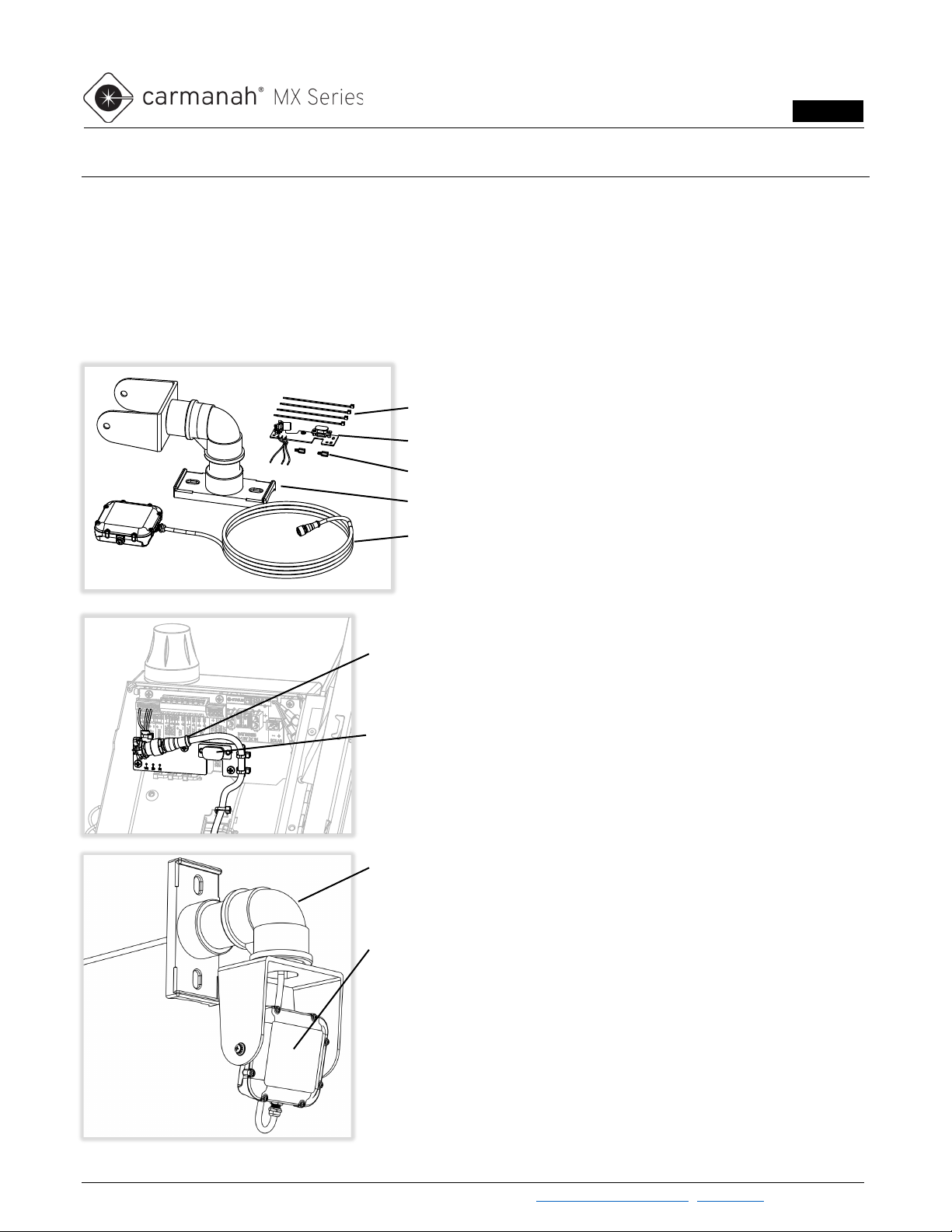
The radar module used in the Radar Detection Kit is the Houston Radar DR600. The radar operates in the 24 -
24.25 GHz band and is configured using PC-based software.
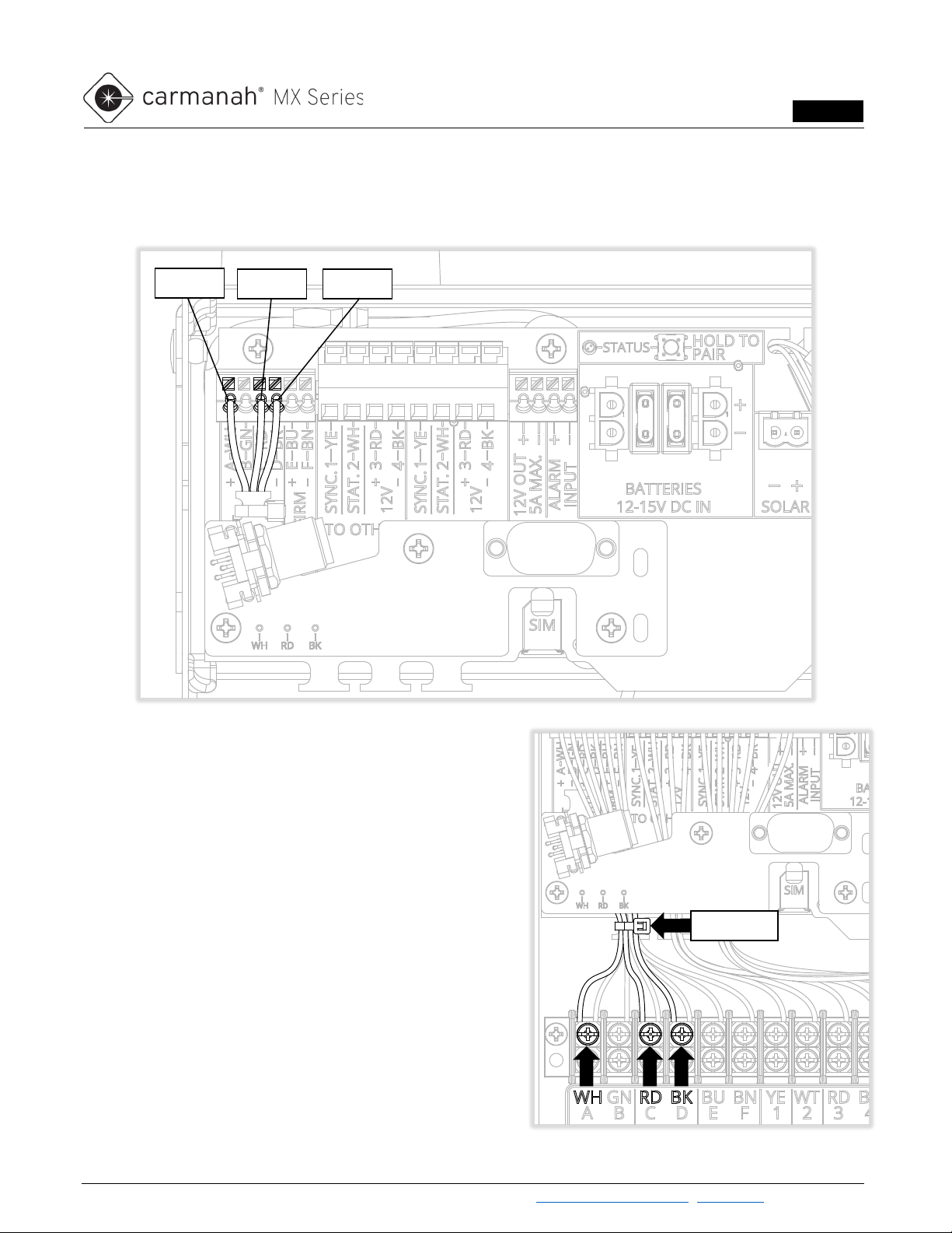
Whenever the radar module detects the motion of a vehicle, it shorts the connected MX power module's input
terminals to ground, activating the flasher modules of that system and those of any linked systems. The radar
module is configured by default to trigger an activation of the MX system(s) whenever it detects a vehicle
approaching at 5 – 206 mph. These and other radar settings can be changed using the Programming Kit, see
Section 4 for details.
When the radar module stops detecting a vehicle’s motion, either because the vehicle has stopped or has moved
out of the detection zone, it stops shorting the trigger input terminals. The connected MX system and any linked
systems will then continue to flash according to each system's Duration setting, which is set separately for each
MX system.
1An MX system is defined as a power module wired to at least one flasher module or trigger kit. The elements of one system
are typically mounted on a single pole.
2Linking two or more MX systems allows any trigger activation to activate the flasher modules of all linked systems and
synchronizes their flashing. See the MX Level 1 Planner and MX Field App Guide for details.
Beacons and LED sign modules will flash continuously by default using the Always On operating
mode. To flash only when triggered by the radar, set the operating mode to Trigger using the MX
Field App. (RRFB modules operate only in Trigger mode.)
To make all linked MX systems flash for the same length of time, set the systems' Duration
setting to be the same. The default Duration setting is 20 seconds; it can be set to a variety of
preset values between 5 and 3600 seconds.

Carmanah Technologies Corp. | 250 Bay St, Victoria, BC V9A 3K5, Canada | 1.250.380.0052 | customersupport@carmanah.com | carmanah.com 4
RADAR DETECTION KIT INSTALL GUIDE
LEVEL 4
3.0 Installation
The following is a summary of the installation sequence of the Radar Detection Kit:
1. Determine installation location on pole for Radar Detection Kit.
2. Install Carmanah MX system on pole per supplied instructions.
3. Install MX radar interface PCBA into MX power module.
4. Drill holes for radar cable and bolts, if required.
5. Fish radar cable, install radar and mount to pole.
6. Aim radar module.
7. Connect and configure radar module, if required.
8. Test system.
3.1 Determine Installation Location on Pole
The radar module should be mounted on the pole so that its front surface directly faces and has an unobstructed
view of oncoming traffic. The radar module cable is 9.8 ft long; to allow sufficient cable slack, the vertical distance
between the radar mount and the MX system should be at most 7 ft.
For optimal radar performance:
•Mount radar at least 6 ft above the ground (for maximum range).
•Minimize the angle between target traffic and the radar module.
3.2 Install Carmanah MX system on Pole
Use the instructions supplied with your system to install the Carmanah MX system onto the pole.
If the radar module can’t be located near the side of the road, it may need to be pointed further
up the road to detect vehicles effectively.

Carmanah Technologies Corp. | 250 Bay St, Victoria, BC V9A 3K5, Canada | 1.250.380.0052 | customersupport@carmanah.com | carmanah.com 5
RADAR DETECTION KIT INSTALL GUIDE
LEVEL 4
3.3 Install Radar Detection PCBA into MX Power Module
1. Open the MX power module lid or door and remove and set aside the two screws indicated from the
Power Module PCBA. Thread the two provided standoffs into the holes and tighten firmly.
2. For MX 100, 200 and 300, use one of the provided cable ties to fasten the wires to the interface PCB
feature shown. For MX 400, route the three wires away from the interface PCB as shown.
3. Use the two screws removed earlier to fasten
the interface PCB assembly to the standoffs.
If the standoffs are difficult to thread in, temporarily loosen the other four power module screws
to improve fastener alignment and prevent cross-threading.
For MX 400, avoid pinching the
existing trigger and module wires
when tightening the interface PCB
screws.
MX 100, MX 200, MX 300
MX 400

Carmanah Technologies Corp. | 250 Bay St, Victoria, BC V9A 3K5, Canada | 1.250.380.0052 | customersupport@carmanah.com | carmanah.com 6
RADAR DETECTION KIT INSTALL GUIDE
LEVEL 4
4. Remove the insulation on the ends of the three wires.
5. For MX 100, MX 200 and MX 300: depress the terminal buttons with a small tool and insert the stripped
wires into the terminal positions shown. Take care to avoid any stray wire strands.
6. For MX 400:
•Remove the left-most cable tie shown.
•Loosen the three terminal screws shown.
•Match the white, red and black wire colors with the
codes on the label under the terminal block as
shown.
•Insert the stripped wires under the terminal plates.
•Re-tighten the terminal screws firmly.
•Replace the removed cable tie with one of those
provided.
White
Red
Black
Remove

Carmanah Technologies Corp. | 250 Bay St, Victoria, BC V9A 3K5, Canada | 1.250.380.0052 | customersupport@carmanah.com | carmanah.com 7
RADAR DETECTION KIT INSTALL GUIDE
LEVEL 4
3.4 Drill Holes for Radar Cable and Mount Through Bolts
If routing the radar cable inside the pole, drill a 5/8" hole in the center of where the radar mount will attach to the
pole. If through-bolting the radar mount, drill two 7/16" holes above and below as shown, through both sides of the
pole.
3.5 Fish Radar Cable, Install Radar & Mount to Pole
Install the radar module into the mount saddle with the cable facing down and fasten with the supplied spacers,
washers and screws as shown. Fish the radar cable through the mount, into the pole and up or down to the
Carmanah MX system. Bolt or band the radar mount to the pole.
Install the radar module with its cable facing down to optimize both detection range and
resistance to water ingress.
Pole mount to pole hardware not supplied.

Carmanah Technologies Corp. | 250 Bay St, Victoria, BC V9A 3K5, Canada | 1.250.380.0052 | customersupport@carmanah.com | carmanah.com 8
RADAR DETECTION KIT INSTALL GUIDE
LEVEL 4
3.6 Aim Radar Module
Adjust the radar tilt and pan so its front face points directly at oncoming traffic. Tighten the hardware firmly to lock
it in place.

Carmanah Technologies Corp. | 250 Bay St, Victoria, BC V9A 3K5, Canada | 1.250.380.0052 | customersupport@carmanah.com | carmanah.com 9
RADAR DETECTION KIT INSTALL GUIDE
LEVEL 4
3.7 Connect and Configure Radar Module
Plug the radar cable connector onto its mate on the interface PCB within the MX power module. Turn the barrel
firmly clockwise to lock the connectors together.
For MX 300, fasten the radar cable to one of the features on the power module chassis with a cable tie.
MX 300

Carmanah Technologies Corp. | 250 Bay St, Victoria, BC V9A 3K5, Canada | 1.250.380.0052 | customersupport@carmanah.com | carmanah.com 10
RADAR DETECTION KIT INSTALL GUIDE
LEVEL 4
For MX 100, MX 200 and MX 400, fasten the radar cable to the two slots on the interface PCB and again to a
strain relief feature on the enclosure as shown.
The radar module is configured from the factory to trigger an activation whenever an oncoming vehicle is detected
approaching at a speed of at least 5 mph. Changes from the default settings are often unnecessary. Reasons for
changing the radar’s configuration include:
•To change the detection speed limits (the minimum and maximum speeds that will trigger an activation)
•To increase or decrease the sensitivity of the radar module
•You’ve ordered the Advanced Statistics option and wish to configure data logging options or read traffic
statistics from the radar module
•To configure the radar module for a less common application (e.g., a radar-activated minimum speed
sign)
If it is necessary to configure the radar module, see Section 4.
MX 100
MX 200
MX 400

Carmanah Technologies Corp. | 250 Bay St, Victoria, BC V9A 3K5, Canada | 1.250.380.0052 | customersupport@carmanah.com | carmanah.com 11
RADAR DETECTION KIT INSTALL GUIDE
LEVEL 4
3.8 Test System
Ensure that the Carmanah MX system to which the radar kit is connected is powered up. See the Carmanah MX
user documentation at support.carmanah.com for details.
Test that the system activates as desired when vehicles approach the radar module. If the LED loads fail to turn
on, check the following:
•The green LED on the back of the radar module flashes every few
seconds (see image at right).
•Nothing is obstructing the radar module’s view of oncoming traffic.
•The radar module is aimed directly at oncoming vehicles.
•Test the LED loads with the Identify System (light bulb) button in the
MX Field App (see the MX Field App Guide for details).
See the Troubleshooting section if the loads still fail to activate.
4.0 Radar Module Connection & Settings
To change the system’s activation behavior, configuration adjustments can be made to the radar module. Before
making radar module configuration changes, please note the following:
•The detection range with factory default settings is typically at least 200 ft.
•Aiming the radar module downwards and/or toward the road slightly can result in later activation.
•Aiming the radar module upwards and/or farther up the road slightly can result in earlier activation.
To make configuration changes, the following components are required:
•Windows 7, 10 or 11 PC (32-or 64-bit versions are supported) running the Houston Radar Advanced
Stats Analyzer program (free download from https://www.houston-radar.com)
•An available USB-A port on the PC
•Radar Detection Programming Kit, consisting of USB-to-Serial adapter and active USB extension cable
•Powered-up Carmanah MX system with Radar Detection Kit installed and radar module connected
The radar module is powered by the Carmanah MX system to which it is connected. To be
configured using the Programming Kit, the radar module must be connected to an operating
Carmanah MX system.
More information about radar module settings can be found in the Houston Radar DR600 User
Manual available at https://www.houston-radar.com. To avoid unintended operation and/or
excessive power consumption, configuration changes should be limited to those discussed in
this section. Other settings should be left at their default values.
Contact Carmanah for assistance with any configuration settings not discussed in this manual.

Carmanah Technologies Corp. | 250 Bay St, Victoria, BC V9A 3K5, Canada | 1.250.380.0052 | customersupport@carmanah.com | carmanah.com 12
RADAR DETECTION KIT INSTALL GUIDE
LEVEL 4
4.1 Connecting to the Radar Module
1. Remove the dust cap from the interface PCB's DB9 connector within the Carmanah MX power module.
2. Plug the USB-to-Serial adapter into the DB9 connector within the MX power module.
3. Plug one end of the USB extension into the USB-to-Serial adapter, and the other end into the USB port of
the PC.
4. Start the Advanced Stats Analyzer program.
5. Select the “Connect to Radar” option from the top banner.
6. Click the “Connect to Radar” button. (Software scans ports until radar found.)
7. Ensure you see a “Radar Found on…” message.
8. Click “OK”.
The radar module is powered by the Carmanah MX system to which it is connected. To be
configured using the programming kit, the radar module must be connected to an operating
Carmanah MX system.
More information about radar module settings can be found in the Houston Radar DR600 User
Manual, available at https://www.houston-radar.com. To avoid unintended operation and/or
excessive power consumption, configuration changes should be limited to those discussed in
this section. Other settings should be left at their default values.
Adjusting settings not outlined in this section may adversely affect radar detection performance.
Contact Carmanah for assistance with any configuration settings not discussed in this manual.

Carmanah Technologies Corp. | 250 Bay St, Victoria, BC V9A 3K5, Canada | 1.250.380.0052 | customersupport@carmanah.com | carmanah.com 13
RADAR DETECTION KIT INSTALL GUIDE
LEVEL 4
4.2 Syncing Radar Clock to Computer
It is recommended that you click the “Sync Radar Clock to Computer” whenever you connect to a radar module.
This is done by clicking the button from the Connection tab of the Connect to Radar window:
After a few moments, the Radar Clock listed will match the computer’s clock.

Carmanah Technologies Corp. | 250 Bay St, Victoria, BC V9A 3K5, Canada | 1.250.380.0052 | customersupport@carmanah.com | carmanah.com 14
RADAR DETECTION KIT INSTALL GUIDE
LEVEL 4
4.3 Adjusting Speed Detection Limits and Sensitivity
Under the “DR600 Setup,” the “Detection & Units” tab are speed settings that influence the system’s activation
behavior:
Speed Limit: vehicles travelling above or below this speed (depending on the “Trigger Event” setting) will trigger
an activation of the connected Carmanah MX system. Default setting is 5 mph.
Maximum Detectable Speed: vehicles travelling above this speed will not trigger an activation of the connected
Carmanah MX system. Default setting is 206 mph.
Detection Sensitivity: the sensitivity of the radar can be tuned with this setting. This can be helpful if the system
is being triggered by vehicles other than those targeted, or if you wish the system to activate when vehicles are a
greater distance away. Default setting is 25%.
Range Boost:increases the distance at which vehicles are detected. Undesired detection of vehicles may result
from enabling Range Boost. Default is off.
Click on “Save Changes” to save the changes to the radar module, or “Close” to disconnect from
the radar module without saving.

Carmanah Technologies Corp. | 250 Bay St, Victoria, BC V9A 3K5, Canada | 1.250.380.0052 | customersupport@carmanah.com | carmanah.com 15
RADAR DETECTION KIT INSTALL GUIDE
LEVEL 4
4.4 Adjusting Trigger Output Configuration
Under the “DR600 Setup,” “Hardware & IO Config” tab are settings that control the system’s activation behavior:
Trigger Event:this setting changes the conditions under which an activation of the connected Carmanah MX
system occurs:
•None: no activations will occur.
•Default: Displayed Target Above Speed Limit (default setting): Carmanah MX system activated
when vehicle detected above configured Speed Limit on “Detection & Units” tab.
•Displayed Target Below Speed Limit: Carmanah MX system activated when vehicle detected
below configured Speed Limit on “Detection & Units” tab.
•Any Displayed Target: Carmanah MX system activated whenever a vehicle is detected, regardless
of speed.
Trigger Direction: this setting changes whether incoming vehicles, outgoing vehicles, or both will trigger the
connected Carmanah MX system. Default setting is Incoming.
Click on “Save Changes” to save the changes to the radar module, or “Close” to disconnect from
the radar module without saving.

Carmanah Technologies Corp. | 250 Bay St, Victoria, BC V9A 3K5, Canada | 1.250.380.0052 | customersupport@carmanah.com | carmanah.com 16
RADAR DETECTION KIT INSTALL GUIDE
LEVEL 4
4.5 Advanced Statistics (Optional)
The optional Advanced Statistics package allows for download and analysis of traffic data using the Houston
Radar Advanced Stats Analyzer program (https://www.houston-radar.com).
For full instructions, please see the Advanced Stats Analyzer user manual.
Settings
Baud Rate: Set to 115200 for maximum data transmission speed if not factory set. Will require a reset of the radar
after changes are saved.
Speed Output Interval: Must be set to 380 ms. Click on the “Set Stats Compatible Interval” button to automatically
assign this value if not factory set.
Statistics Options: Sets how long the radar will collect data in “speed bins” before it saves to memory and starts a
new record. Records are only able to hold up to 255 vehicles. Default setting is 5 minutes.
Hi Resolution Stats Logging: Sets the resolution of speed bins; 3 MPH or 5 MPH. Default setting is disabled or 5
MPH.
Click on “Save Changes” to save the changes to the radar module, or “Close” to disconnect from
the radar module without saving.
Up to 12 days of data can be recorded before it is rolled over when stats records are collected
every one minute. When set to every five minutes it is up to 60 days of data.

Carmanah Technologies Corp. | 250 Bay St, Victoria, BC V9A 3K5, Canada | 1.250.380.0052 | customersupport@carmanah.com | carmanah.com 17
RADAR DETECTION KIT INSTALL GUIDE
LEVEL 4
Collecting Data
Once you have the radar settings configured and the system is deployed it is recommended to erase any
collected data. Click on “Erase Radar Data” and then “OK.”
Allow the system to collect data for a minimum of five minutes, or the time value set for the stats interval. This is
when you can test the system by driving through the wrong-way zone. The longer the collection time, the richer
the data will become.
Retrieving Data
Once you have enough runtime on the system, connect to the radar as in Section 4.1.
1. Click on Read Traffic Stats From Radar to download the data. Click on Save and then Yes to save into a
project.
2. Create a new project on the left-hand side and drag over the data into the project and then click Import.
If you have successfully downloaded the data you can click on “Erase Radar Data” to start
collecting new data.

Carmanah Technologies Corp. | 250 Bay St, Victoria, BC V9A 3K5, Canada | 1.250.380.0052 | customersupport@carmanah.com | carmanah.com 18
RADAR DETECTION KIT INSTALL GUIDE
LEVEL 4
Analyzing Data
Once you have the data imported into a project you can analyze the data.
1. Go to the project you created on the main screen of the Stats Analyzer screen and click Open.
2. Ensure your data set is imported under the “Manage Imported Data” tab.
3. Navigate back to “Date Selection View” and select the dates you wish to filter the data from.
4. Set your Speed Limit on the right-hand side of the screen.
5. Click on all report checkboxes you wish to apply to the report.
6. Click on “Analysis Report.”
If there are no vehicles detected/logged in the data you will be warned after clicking Analysis
Report.

Carmanah Technologies Corp. | 250 Bay St, Victoria, BC V9A 3K5, Canada | 1.250.380.0052 | customersupport@carmanah.com | carmanah.com 19
RADAR DETECTION KIT INSTALL GUIDE
LEVEL 4
5.0 Troubleshooting
Symptom
Possible Cause and What to Check
LED fixtures fail to turn
on when a vehicle
approaches.
1. Object obstructing radar path:
•Ensure nothing obstructs radar module’s view of target traffic.
2. Radar not aimed correctly:
•Ensure radar module pointing directly at target traffic.
3. Radar module not connected properly:
•Ensure green LED on back of radar module flashes every few seconds.
•Ensure circular connector fully mated in Carmanah MX power module
and barrel firmly tightened.
4. Problem with connected Carmanah MX system:
•Confirm connected Carmanah MX system powered and operating
correctly; test LED loads with Identify System (light bulb) button in MX
Field App (see MX Field App Guide for details).
5. Radar module improperly configured:
•Connect to radar module and check settings (see Section 5).
6. Incorrect operation mode selected on MX power module:
•Set operation mode to Trigger in MX Field App (see MX Field App
Guide for details).
LED fixtures turn on
when there is no traffic
approaching.
1. Radar being triggered by unintended object movement:
•Ensure there are no fans or other moving objects in direction radar is
pointed.
2. Other linked Carmanah MX system causing unwanted activation:
•Isolate systems as required by creating a new link for each system to
be isolated using MX Field App (see MX Field App Guide for details).
LED fixtures turn on
too early (when vehicle
too far away).
1. Radar aimed too high and/or too far up road:
•Aim radar module toward oncoming traffic.
2. Radar sensitivity set too high:
•Reduce radar sensitivity setting (see Section 4.3).
•Disable Maximum Detection Sensitivity setting (see Section 4.3).
LED fixtures turn on
too late (when vehicle
too close).
1. Radar module dirty or obstructed:
•Ensure radar module is clean and nothing obstructs its view of traffic.
2. Radar aimed too low and/or too far in toward road:
•Aim radar module toward oncoming traffic.
3. Radar sensitivity set too low:
•Increase radar sensitivity setting (see Section 4.3).

Carmanah Technologies Corp. | 250 Bay St, Victoria, BC V9A 3K5, Canada | 1.250.380.0052 | customersupport@carmanah.com | carmanah.com 20
RADAR DETECTION KIT INSTALL GUIDE
LEVEL 4
Symptom
Possible Cause and What to Check
LED fixtures on for too
long/short a duration
after vehicle detected.
1. Adjust Duration setting on MX system(s):
•Duration is set separately for each MX system.
•See MX Field App Guide for details.
LED fixtures triggered
by outgoing vehicles.
1. Radar module configured to detect outgoing vehicles:
•Ensure “Trigger Direction” setting on radar module is configured
correctly (see Section 4.4).
All LED fixtures (local
system and linked
systems) activating
inconsistently.
1. Radar module dirty or obstructed:
•Ensure radar module is clean and nothing obstructs its view of traffic.
2. Radar sensitivity set too low:
•Increase radar sensitivity setting (see Section 4.3).
3. Radar “Speed Limit” set incorrectly:
•Adjust “Speed Limit” setting (see Section 4.3).
4. Radar “Trigger Event” set incorrectly:
•Adjust “Trigger Event” setting (see Section 4.4).
Remote wireless
systems do not
activate; local system
activates when a
vehicle approaches.
1. MX systems not linked:
•Link desired MX systems with MX Field App.
2. Linked MX systems too far apart:
•Ensure units are not too far apart: ideal, 500 ft (152 m); maximum,
1,000 ft (305 m) unobstructed line of sight.
3. Objects obstructing wireless communication between units:
•Check for barriers or obstructions between systems such as buildings
or billboards.
Other manuals for MX Series
7
Table of contents
Other Carmanah Radar manuals

Carmanah
Carmanah SPEEDCHECK Parts list manual

Carmanah
Carmanah SpeedCheck-15 User manual

Carmanah
Carmanah SpeedCheck 12 User manual

Carmanah
Carmanah SpeedCheck-15 User manual

Carmanah
Carmanah SPEEDCHECK 15 User manual

Carmanah
Carmanah SpeedCheck 12 User manual

Carmanah
Carmanah E Series User manual

Carmanah
Carmanah SpeedCheck-18 Parts list manual

Carmanah
Carmanah SpeedCheck-15 Parts list manual

Carmanah
Carmanah SpeedCheck-15 Parts list manual