Owner’s Manual | Model
R820
Carmanah Technologies Inc. Copyright © 2006
Document number: MAN_ROAD R820 Owner's Manual 36983_vB
Last revised: November 7, 2006
10
the system. If the customer does not attempt to enter the configuration mode upon power-up, but
simply presses the button, the previously stored settings will be utilized.
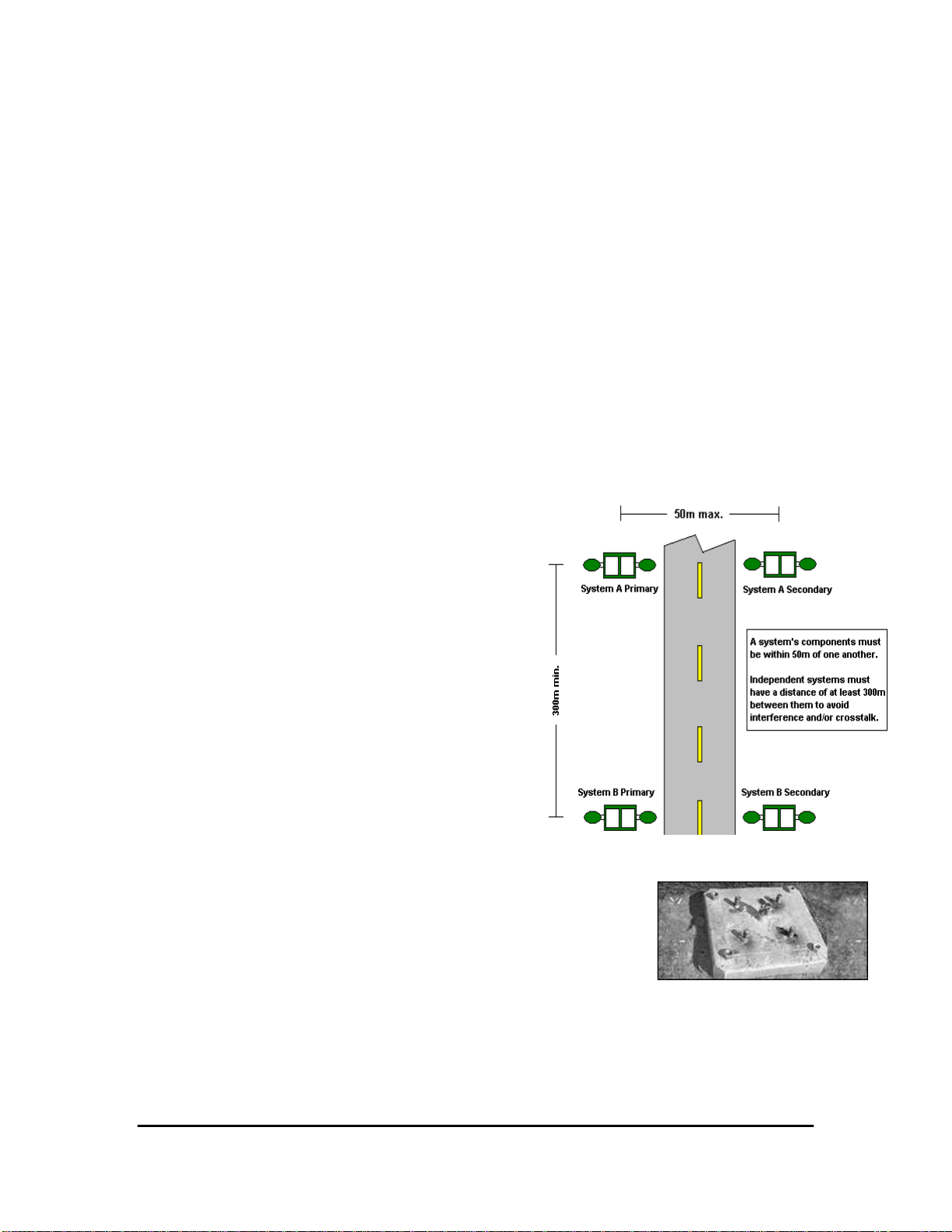
Each of the R820 units in a crosswalk installation must be configured individually, with the same
settings. After product configuration is completed, the settings are stored in non-volatile memory.
If the batteries are re-connected, and no change in configuration is desired, the product will
continue to operate with its previous settings. The R820 system has two user-configurable
parameters:
Flash Duration - The amount of time the light will flash after each button press by a pedestrian.
The flash duration is set in 5-second increments, up to one minute. This command sequence sets
the length of time the system will flash after one button press, and should consider the length of
time it will take a pedestrian to cross the street.
Timer Delay - The amount of time the light will delay between uses before accepting a new
button press. The delay is set in 5-second increments, up to one minute. If the delay is set to 0, a
button press while the light is flashing causes the light to restart its timer at the time of the button
press (the light will flash for "flash duration" seconds after the new button press).
3.3.1
Factory Flash and Timer Delay Settings
The default factory configuration is a 20 second flash duration with a zero second delay between
activations. What this means is, if a second pedestrian should press the button while the light is
flashing, the light will flash for 20 seconds starting from the moment the button is pressed.
To customize the flash duration and timer delay, follow the
instructions provided in the next section.
3.3.2
Battery Connection, Customized Flash
Duration and Timer Delay
The R820 ships with two battery packs that are disconnected
for shipping. Configuration of flash duration and timer delay is
performed during the five minutes immediately following
battery connection. Battery connection is as outlined below:
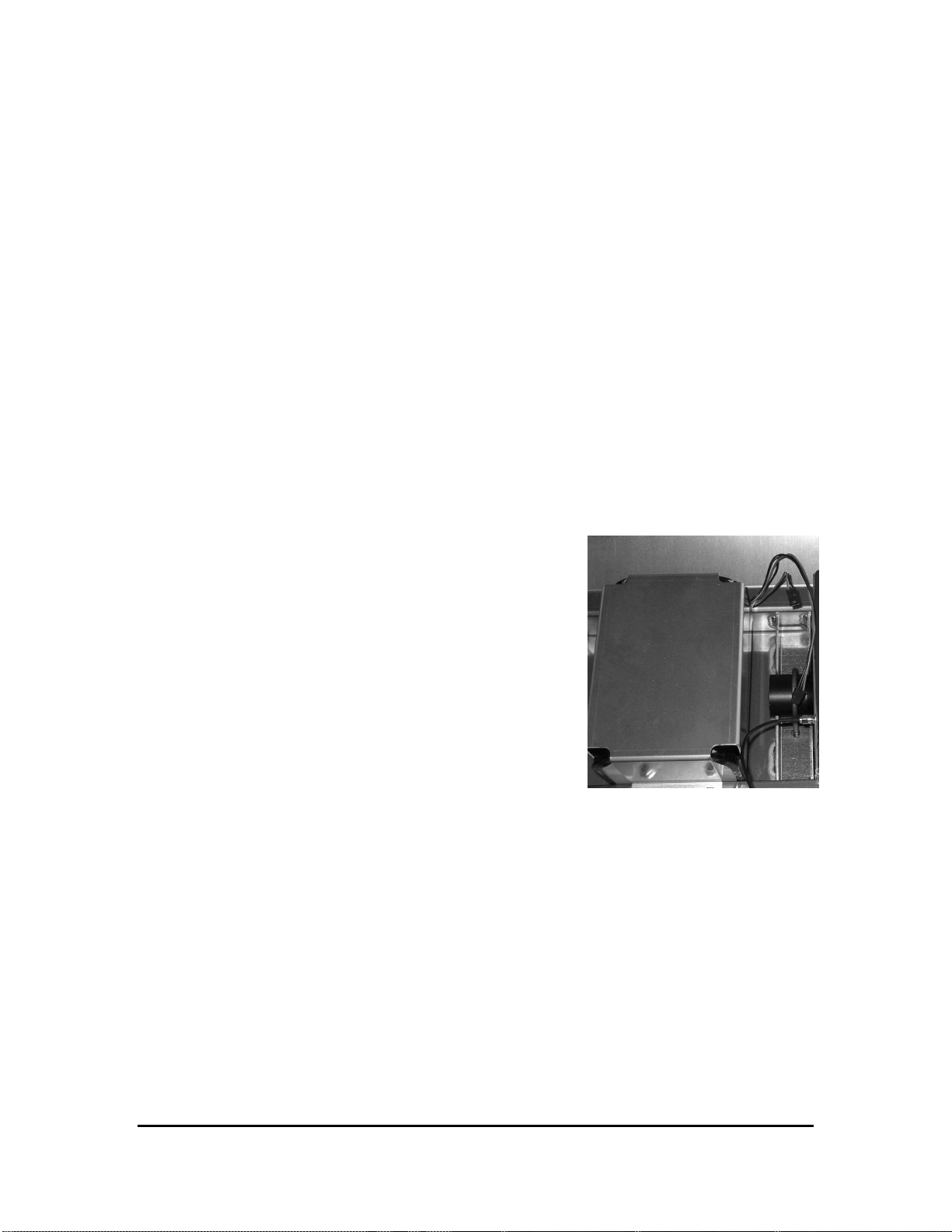
1. Find the two connection wires from each battery pack:
the longer terminating with a male connector, and the
shorter terminating with a female connector.
2. With the bases of the batteries facing the person doing
the installing, attach the long harness (male) of the left
side battery to the short harness (female) of the right
side battery.
3. Attach the long harness (male) from the right hand battery to the “Battery” connection on
the PCB harness end of the battery nearest to the end of the PCB connectors. The short
harness (female) from the left hand battery will remain unused.
4. The flash duration and timer delay for the system are now ready to configure as per the
table below:
Left side battery pack
showing short (female) and long
(male) leads