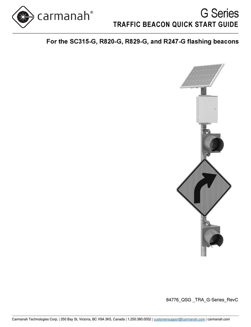
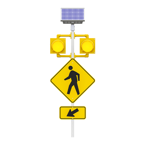
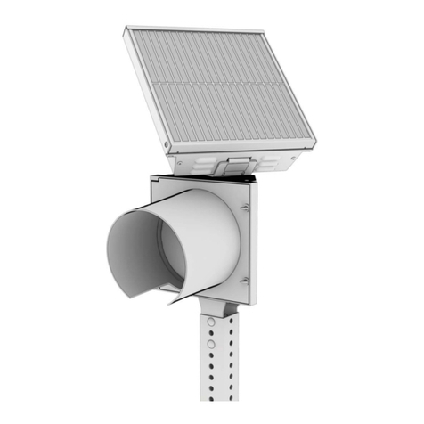
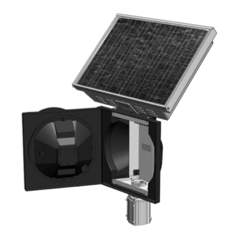
Carmanah R829 User manual

OWNER’S MANUAL
Solar LED School Zone Beacon – Model R829
The world’s most advanced solar LED school zone beacon.
No external wiring or bulb replacement.
Maintenance-free for up to 5 years.
© November 7, 2006, Carmanah Technologies Corp.
www.carmanah.com
Technical Support: customerservice@carmanah.com
Toll Free in North America: 1 (877) 722-8877
International: + (250) 380-0052 | Fax: + (250) 389-0040
R829 – 37234


Owner’s Manual |
R829
3
Carmanah Technologies Corp. Copyright © 2006
Document number: MAN_ROAD_R829 Owner's Manual 37234_vC
Last revised: November 7, 2006
Table of Contents
1.0 Introduction.............................................................................................................4
1.1 How It Works......................................................................................................4
2.0 Component Identification....................................................................................5
3.0 Tools and Materials Required.............................................................................6
3.1 Tools Required...................................................................................................6
4.0 Product Assembly and Installation....................................................................6
4.1 Selecting a Pole .................................................................................................6
4.2 Installing the R829 Switch Enclosure..................................................................7
4.3 Creating a Concrete Base ..................................................................................7
4.4 Removing the Solar Panel and Battery Covers...................................................7
4.5 Preparing the Solar Panel Module......................................................................7
4.6 Locate the Signal Head(s) and Sign...................................................................8
4.7 Wiring the Switch Enclosure...............................................................................8
4.8 Mounting the Head Assembly.............................................................................8
4.9 Erect the Pole.....................................................................................................9
4.10 Install the Upper Signal Head.............................................................................9
4.11 Installing the Lower Signal Head (if equipped)....................................................9
4.12 Connect the Batteries.......................................................................................10
4.13 Install Bird Deterrents on the Module Housing..................................................10
4.14 Attach the Solar Panels to the R829 Electronics...............................................11
4.15 Final Adjustments.............................................................................................11
5.0 Maintenance and Product Care ........................................................................12
6.0 Troubleshooting................................................................................................12
7.0 Service and Additional Products......................................................................13
7.1 Customer Service and Warranty.......................................................................13
7.2 Additional Products ..........................................................................................13
8.0 Product Specifications......................................................................................14
9.0 Appendix A – R829 Quick Start Guide .............................................................15
10.0 Appendix B – R829 Calendar Configuration Instructions...............................18

Owner’s Manual |
R829
4
Carmanah Technologies Corp. Copyright © 2006
Document number: MAN_ROAD_R829 Owner's Manual 37234_vC
Last revised: November 7, 2006
1.0 Introduction
Thank you for purchasing the Carmanah Model R829 school zone warning beacon, “the world’s
most advanced solar-powered LED school zone beacon.” Using LED illumination, the unit is
designed to operate flawlessly with no scheduled maintenance (other than routine cleaning) for
up to 5 years.
Combining advanced electronics and software with an innovative, patented combination of solar-
power and LED technology, the Model R829 has been designed to operate under all
environmental conditions at most locations throughout North America.
1.1
How It Works
Unlike programmable time clock systems, the R829 is programmed using an intuitive Windows-
based graphical user interface. The settings can be easily transferred to multiple R829 units.
Uploading the programmed settings occurs on site quickly and efficiently via a wireless link.
The R829 is completely power-autonomous - no wiring to an external power supply is required.
This allows a simple, low-cost installation even in locations where external power is unavailable.
It operates using solar-charged batteries that are maintenance free for up to five years when
properly installed.
The R829 can be ordered with one or a pair of flashing lights for each unit. When there are two
flashers, these can be mounted as a vertical dual flasher, a horizontal dual flasher, or a bi-
directional flasher depending on location requirements. When activated, drivers will see the lights
as a “bouncing-ball effect.”
Refer to the R829 School Zone Beacon Quick Start Guide in Appendix A or the School Zone
Calendar Configuration applications help files in Appendix B, and also included in the
programming software, for detailed information on setting up and uploading a custom-
programmed calendar to the R829.

Owner’s Manual |
R829
5
Carmanah Technologies Corp. Copyright © 2006
Document number: MAN_ROAD_R829 Owner's Manual 37234_vC
Last revised: November 7, 2006
2.0 Component Identification
1. Head Module.
2. Solar Panel.
3. Radio Antenna.
4. Signal Head (one or two).
5. Signal Head Mounting Bracket.
6. Sign (not included).
7. Pole (not included).
1
2
3
4
4
5
5
6
7

Owner’s Manual |
R829
6
Carmanah Technologies Corp. Copyright © 2006
Document number: MAN_ROAD_R829 Owner's Manual 37234_vC
Last revised: November 7, 2006
3.0 Tools and Materials Required
It is a good idea to begin the installation process in the shop. Take the time to read through this
manual to determine what tasks can be completed in the shop prior to the field installation portion
of the job.
Note: This product requires a concrete base that is designed for the pole to be used. Ensure
that this base is prepared beforehand.
3.1
Tools Required
•Socket set
•Drill and drill bits
•Screwdrivers
•Fine-tip felt marker
•Tap and die set
•Fish tape
•12-15 ft. ladder
•Level
•Knowledge of local latitude
•Compass (to measure direction)
•Compass (to measure angles)
4.0 Product Assembly and Installation
Installation time is approximately one hour in the shop and two hours in the field per R829
system. No trenching, external cabling, traffic disruption or site remediation required. Once
installed, the R829 is designed to operate for up to 5 years with virtually no maintenance other
than routine cleaning. After approximately 5 years, battery replacement will be required.
4.1
Selecting a Pole
Typically, a 10-foot “Type1” pedestrian pole is used for the installation. A “Type 9”, with a mast
arm for an over the road configuration or any other pole that has a 4” to 4.5” OD top cap, can also
be used.
Note: If a 4” OD pole is being used, longer bolts will be required than those provided.
Figure 1

Owner’s Manual |
R829
7
Carmanah Technologies Corp. Copyright © 2006
Document number: MAN_ROAD_R829 Owner's Manual 37234_vC
Last revised: November 7, 2006
4.2
Installing the R829 Switch Enclosure
Drilling the holes for the switch enclosure hardware is typically much easier to do while the pole is
in the shop. This should make the final installation in the field go quicker.
Ensure that the location of the switch enclosure will not interfere with the signal heads and
signage when they are later installed (see Figure 2).
Drill and tap two holes for mounting the plate. Drill 5/8” hole for the wire, then de-burr the edges
to avoid damaging the wires during installation.
4.3
Creating a Concrete Base
As shown in Figure 3, a concrete foundation with the necessary mounting hardware has been
poured prior to pole installation. The procedure for doing this is outside the scope of this manual.
4.4
Removing the Solar Panel and Battery Covers
First remove the cover with the solar panels from the top of the head module, and then remove
both covers from the two battery modules (see Figure 4).
4.5
Preparing the Solar Panel Module
Turn the solar module upside down to prepare it for installation. Prop up the end of the R829 that
has the radio antenna (see Figure 5) to ensure that this delicate component is not damaged
during assembly. One of the battery covers can be used as a support.
Figure 2
Figure 3
Figure 5
Radio Antenna
Solar Module
Figure 4
Battery Cover

Owner’s Manual |
R829
8
Carmanah Technologies Corp. Copyright © 2006
Document number: MAN_ROAD_R829 Owner's Manual 37234_vC
Last revised: November 7, 2006
4.6
Locate the Signal Head(s) and Sign
Before drilling any holes for mounting the signal head(s) or signs, do the layout for the locations
of the signal head(s) and sign at this time. See the layout in Figure 6 as an example.
Once the location of the signal head(s) and sign are determined, drill a hole to allow the wiring to
go from the lower signal head, through the pole, up to the solar module. The hole for the wiring
should be large enough to allow the use of a fish tape during installation.
Note: De-burr all wiring holes to eliminate any sharp edges that could damage the wires during
installation.
4.7
Wiring the Switch Enclosure
Use a fish tape to run the longest wire from the solar module head to the switch enclosure.
Carefully connect the switch enclosure wire to the wire running down from the solar module head
to the switch box through the mounting pole and then thread it into the pole so that it won’t be
pinched. Fasten the switch enclosure to the mounting pole.
Carefully thread the longest signal head wire through the mounting pole down to the location of
the lower signal head. Leave the wire dangling outside the pole. It will be used later when
installing the signal head.
4.8
Mounting the Head Assembly
Install the head assembly on the top of the pole before raising the pole into position (see Figure
8). Do this with caution so that the wiring is not pinched between the top cap and the pole.
Finger tighten the bolts that secure the top cap to the pole. Final tightening will happen at the end
after the solar panels are correctly oriented for maximum solar charging.
Note: If a 4” OD pole is being used, longer bolts will be required than those provided.
Figure 6
Figure 7

Owner’s Manual |
R829
9
Carmanah Technologies Corp. Copyright © 2006
Document number: MAN_ROAD_R829 Owner's Manual 37234_vC
Last revised: November 7, 2006
4.9
Erect the Pole
Assuming that the pole base is already in place, stand the pole upright and bolt it to the base
using the mounting hardware (see Figure 9).
4.10
Install the Upper Signal Head
Loosen the bolts, which hold the top cap to the pole so that the top cap can be rotated. Open the
cover of the top signal head and install the unit onto the upper elbow as shown in Figure 10.
Hand-tighten the nut for now.
Locate the bottom bracket as shown in Figure 11 and, as with the top elbow, tighten the nut finger
tight for now. The bottom bracket can be fastened to the pole with bolts or stainless steel straps.
Connect the signal wire from the head assembly to the signal head and close the cover.
4.11
Installing the Lower Signal Head (if equipped)
The wire for the lower signal head should already be hanging out of the hole in the pole. Feed
the wire through one of the brackets and fasten the bracket to the pole with bolts or stainless
steel straps.
Figure 8
Figure 9
Figure 10
Figure 11
Upper El
bow

Owner’s Manual |
R829
10
Carmanah Technologies Corp. Copyright © 2006
Document number: MAN_ROAD_R829 Owner's Manual 37234_vC
Last revised: November 7, 2006
Open the cover of the signal head, and install the unit onto the elbow. Finger tighten the nut.
Locate the bottom bracket and tighten the nut finger tight. The bottom bracket can then be
fastened to the pole with bolts or stainless steel straps.
Connect the signal wire from the solar panel module to the signal head and close the cover.
4.12
Connect the Batteries
Remove the cover from the control module and rotate the head unit so that the connection points
are facing the installer and the wiring label is visible.
Each battery has two connectors. With the harnesses facing the installer, connect the female
terminal of the right battery to the male terminal of the left battery. Connect the male terminal of
the right battery to the control module. A label inside the control module indicates the connector
location.
Note: If the above procedure is followed correctly, the left battery will have an unused or “extra”
harness.
4.13
Install Bird Deterrents on the Module Housing
The bird deterrents discourage birds from using the top edge of the R829 as a perch, thus
ensuring that the solar panels remain as clean as possible.
Place the top cap with solar panels onto a stable work area. Attach the three bird deterrents with
sheet metal screws, using the predrilled holes on the top cap as a means of identifying their
location.
Figure 12
Figure 13
Figure 14

Owner’s Manual |
R829
11
Carmanah Technologies Corp. Copyright © 2006
Document number: MAN_ROAD_R829 Owner's Manual 37234_vC
Last revised: November 7, 2006
4.14
Attach the Solar Panels to the R829 Electronics
Place the cover with the solar panels onto the top of the unit so that the wiring can reach the
control module. Note that the clearance notch will locate above the antenna. Connect the solar
panel harness to the solar panel interface harness already connected on the card.
Replace the cover on the control module. Ensure that the wires come straight out of the
connectors and are pinched by the foam. Fasten the solar panel top to the main body using the
screws provided.
4.15
Final Adjustments
The Carmanah R829 is solar powered; therefore it is critical to properly position the unit in
relation to the optimum angle of the sun in order to achieve maximum solar power generation. To
do this, angle the solar panel towards the equator (use of a compass is recommended) and tip it
upwards at an angle equal to the latitude of installation plus 5 degrees. For example, Vancouver
B.C. would require that the solar panel point south at an angle of 54 degrees up from the horizon
(49 degrees Latitude plus 5 degrees).
Next, tighten the setscrew on the cap. Position the lenses towards oncoming traffic and tighten
the bolts inside the signal heads. Finally, attach the sign to the pole to complete the installation.

Owner’s Manual |
R829
12
Carmanah Technologies Corp. Copyright © 2006
Document number: MAN_ROAD_R829 Owner's Manual 37234_vC
Last revised: November 7, 2006
5.0 Maintenance and Product Care
Although the R829 is designed to be maintenance free, maximum performance can be
maintained with clean solar panels and lenses. Clean the unit on a regular basis, especially if it is
installed in a dusty environment. Use water and a soft sponge or cloth for cleaning and a mild,
non-abrasive cleaning agent for more stubborn residue. Rinse well.
Note: Pressure washers should not be used. Water forced up into the louvers may soak internal
components.
•Clean solar panels more frequently during drier months, as they may become soiled more
quickly.
•Check all electrical and mechanical connectors yearly to ensure they are clean, secure
and undamaged.
•The main battery housing has several vents and drain holes. Ensure that they are free of
debris.
•Visual inspect exterior assembly for cracks, missing or broken hardware or other potential
problems.
Note: Exercise extreme caution when handling the battery packs. They are capable of
generating enormous short-circuit currents. Remove all jewelry (bracelets, metal-strap watches,
rings) before attempting to handle or disassemble the battery packs.
Note: The batteries are comprised of four sealed lead-acid cells each. Consult your local
municipal by-laws for information on recycling the cells.
Do not discard batteries in the garbage. Please recycle!
6.0 Troubleshooting
The most obvious fault that may occur with the R829 is that the light will not flash. If this is the
case, there are two things that can be checked correct this problem:
1. Check the battery connection and the LED signal head connection to ensure that the
connectors are fully inserted. As the light is designed to function as soon as the battery is
plugged in, this should be fairly simple to diagnose.
2. Certain units have batteries that utilize inline fuses. In the
case of system malfunction, open the inline fuseholder
(pictured left), and check the state of the fuse. If the interior
filament is intact, the fuse itself is functional, otherwise
replace the fuse with Cooper-Bussman model ABC-4 (4-
amp fuse).
If your R829 light still will not operate correctly, contact
Carmanah’s Customer Service Department at 1-877-722-8877 or contact your distributor.

Owner’s Manual |
R829
13
Carmanah Technologies Corp. Copyright © 2006
Document number: MAN_ROAD_R829 Owner's Manual 37234_vC
Last revised: November 7, 2006
7.0 Service and Additional Products
7.1
Customer Service and Warranty
Before contacting Carmanah’s customer service department, please have the serial number of
the Model R829 available, a brief description of the problem, as well as all details of the
installation.
Carmanah products are covered by a standard 3-year pro-rated warranty. A warranty card is
supplied with each unit. The warranty can also be viewed online at:
http://www.carmanah.com/content/products/warranty/
To contact Carmanah’s Customer Service Department:
Mail: Carmanah Technologies Corp.
Building 4, 203 Harbour Rd.
Victoria, BC Canada V9A 3S2
Phone: (250) 380-0052
1 877-722-8877 (Toll Free Canada & U.S.)
Fax: (250) 380-0062
Email: customerservice@carmanah.com
Website: www.carmanah.com
7.2
Additional Products
Carmanah offers a variety of solar-powered and energy efficient LED lighting products. For
roadway applications, Carmanah also manufactures solar 24 hour flashing beacons and
pedestrian crosswalk flashers, as well as LED internally illuminated street-name signs and traffic
signs. For more information, please visit our website at: www.roadlights.com.

Owner’s Manual |
R829
14
Carmanah Technologies Corp. Copyright © 2006
Document number: MAN_ROAD_R829 Owner's Manual 37234_vC
Last revised: November 7, 2006
8.0 Product Specifications
Light Output
Daytime Effective Intensity, Flashing 570 Cd
Daytime Peak Intensity 800 Cd
Nighttime Effective Intensity, Flashing 285 Cd
Nighttime Peak Intensity 400 Cd
Average Day Range 0.5 mi/0.75km
Operation
Daily Operational Profile 2 hrs. Continuous or intermittent
(Example: 240 activations daily at 30 sec. per activation)
Required Solar Isolation for 2 hrs.
Daily Operational Profile
Continuous Operation Without Sun 30 Days minimum
Lifespan of LEDs Up to 100,000 hrs.
Color Output Yellow
Dominant Wave Length 590 nm
Flash Pattern/On Time/Off Time 0.55s/0.55s(MUTCD Compliant
“Bouncing Ball”)
Battery Capacity 400 Watt-hour
Lens
Colors Yellow (ITE compliant)
Material 8” or 12” polycarbonate is hard coated
for abrasion
Communications
RF Transmission 900 MHz (Frequency hopping spread
spectrum)
Transmit Output Power Less than 100 mW
Effective Range 165 ft./50 m/line of site operation
Antenna Type Omni-directional dipole
Maximum Number of Independent Systems 64
Operating Temperatures
Optimal Ambient Range -4°to 77°F (-20°to +25° C)
Maximum Ambient Temperature Range -40°to 176°F (-40°to +80°C)
Storage Temperature 68°+/- 5°F (20°+/- 5°C)
Housing
Head and Support Structure Powder coated aluminum
Signal Housing Injection Molded UV stabilized
polycarbonate
Switch Housing Powder Coated Steel
Patents
Trademark and Patents Patents Pending

Owner’s Manual |
R829
15
Carmanah Technologies Corp. Copyright © 2006
Document number: MAN_ROAD_R829 Owner's Manual 37234_vC
Last revised: November 7, 2006
9.0 Appendix A – R829 Quick Start Guide
This Quick Start Guide is intended to provide basic information on installing the software on your
computer and uploading your first calendar.
For more detailed information on configuring your School Zone Beacon, please refer to Appendix
Bor the Help Folder on your CD.
System Requirements
Minimum 266MHz, 32MB RAM
Windows 98, 2000, XP supported
Note to XP users: The drivers are not certified by Microsoft and a warning message will appear
during installation. This simply means that the chip manufacturers have not paid to have the
drivers certified for Windows XP. Ignore the messages and continue with the driver installations –
they are fully compatible and will perform correctly.
Interface Installation and Configuration
USB Driver Installation
1. Plug the Interface Box into your computer using the supplied USB cable.
2. The “Found New Hardware Wizard” will appear – this may take some time depending on your
system.
3. Click “Next.”
4. Follow the default for the drivers search. Click on “Next.”
5. Select “Specify a Location” only! Click on “Next.”
6. Insert the CD into your CDROM drive.
7. Click “Browse.”
8. Navigate to the CDROM drive and double-click on “Interface Box Drivers.”
9. Click “Open” (the default that is already selected).
10. You will be returned to the Wizard. Click “OK.”
11. Confirm that the driver found is ftdibus.inf. Click “Next” to install the driver.
12. Click “Finish.”
Serial to USB Interface Installation
1. The “Found New Hardware Wizard” will appear – this may take some time depending on your
system.
2. Click “Next.”
3. Use the default selection, click “Next.”
4. Select “Specify a Location” only! Click “Next.”
5. Confirm that the location YourCDROMDrive:\Interface Box Drivers is selected. Click “OK.”

Owner’s Manual |
R829
16
Carmanah Technologies Corp. Copyright © 2006
Document number: MAN_ROAD_R829 Owner's Manual 37234_vC
Last revised: November 7, 2006
6. Confirm that ftdiport.inf is found.
7. Click “Next.”
8. You will be returned to the Wizard. Click “Finish.”
Installing the Software
1. Access the CDROM and run Setup.exe
2. The Wizard will appear – follow the prompts using the default selections.
Installation is now complete.
Configuring the Interface Box
1. Open the application using the icon created on your desktop. When the calendar
configuration window opens, pull down the Configure menu. Select “Interface Box.”
2. Select which port the Interface Box is connected to. Keep the Baud Rate set to the value of
115200.
3. Ensure the Select Mode is set to Secondary.
4. Ensure the Channel selected is 0.
5. Click on Configure. The Interface Box is now being set up in preparation for communicating
with your School Zone Beacon.
6. If setup is successful, you will see “SUCCESS!”. Your Interface Box is now ready for use
with your Beacon.
Creating a Calendar
This is best performed prior to going to the location of your School Zone Beacon. Information on
advanced features such as selecting “Schedules and Events” for your entire year, saving your
new calendar and determining which calendar is currently loaded in the Beacon can also be
found in the Help Folder on the software CD.
Note: When naming and saving your newly created calendar, it is important to note that the file
name you choose cannot have any blank spaces in it.

Owner’s Manual |
R829
17
Carmanah Technologies Corp. Copyright © 2006
Document number: MAN_ROAD_R829 Owner's Manual 37234_vC
Last revised: November 7, 2006
Uploading your New Calendar
1. Open the Switch Box and flip the switch to the “Manual Override” position. You will notice
that the lights begin flashing immediately. This is normal because it tells you the School
Zone Beacon is functional. The lights will always flash when the switch is in the OVERRIDE
position.
2. Have a look at the LED on the end of the Interface Box – it should be glowing green. This
tells you that the Interface Box and School Zone Beacon recognize each other and are ready
to communicate. If the LED is not on, check the configuration of the Interface Box using the
Interface Installation and Configuration instructions.
3. Navigate to the Communicate Menu and click on the Send Calendar menu item. Wait for the
calendar to be sent.
4. Flip the switch in the pole-mounted box back to the “Auto” position.
Note: Don’t forget to do this, or your Beacon will flash continuously until the batteries are
dead – it will NOT follow the times loaded in the calendar.
Your School Zone Beacon is now in service.
Note: If you have any problems or questions during the set-up of your new School Zone Beacon,
visit the FAQ and Troubleshooting section of the Help File located on the CD.
Figure 1. Pole mounted box with manual override switch.

Owner’s Manual |
R829
18
Carmanah Technologies Corp. Copyright © 2006
Document number: MAN_ROAD_R829 Owner's Manual 37234_vC
Last revised: November 7, 2006
10.0 Appendix B – Calendar Configuration
Instructions
Table of Contents
1.0 Getting Started ......................................................................................................19
1.1 System Requirements and Program Installation...................................................19
1.2 Configuring the Interface Box...............................................................................19
1.3 Creating a Calendar.............................................................................................20
1.3.1 Creating a New Calendar...............................................................................21
1.3.2 Setting the Start Day......................................................................................22
1.3.3 Setting the End Day.......................................................................................24
1.3.4 Turning the Lights OFF on a Specific Day......................................................25
1.3.5 Turning the Lights ON for a Specific Day at Specific Times ...........................26
1.4 Adjusting the Brightness.......................................................................................28
1.5 Sending a Calendar to the School Zone Beacon..................................................29
2.0 File Operations......................................................................................................31
2.1 New......................................................................................................................31
2.2 Load.....................................................................................................................31
2.3 Save.....................................................................................................................31
2.4 Save As ...............................................................................................................31
2.5 Quit......................................................................................................................31
3.0 Calendar Operations.............................................................................................31
4.0 Communicate Operations.....................................................................................31
4.1 Send Calendar.....................................................................................................31
4.2 Read Calendar.....................................................................................................32
5.0 Configure Operations............................................................................................32
5.1 Interface Box........................................................................................................32
6.0 FAQs and Troubleshooting ..................................................................................32
6.1 Frequently Asked Questions ................................................................................32
6.2 Troubleshooting ...................................................................................................33

Owner’s Manual |
R829
19
Carmanah Technologies Corp. Copyright © 2006
Document number: MAN_ROAD_R829 Owner's Manual 37234_vC
Last revised: November 7, 2006
School Zone Calendar Configuration Help
The school zone calendar configuration program is used to create and modify calendars that will
be programmed into a school zone beacon.
1.0 Getting Started
1.1 System Requirements and Program Installation
Minimum 266MHz, 32MB RAM
Windows 98, 2000, XP supported
Note to XP users: The drivers are not certified by Microsoft and a warning message will appear
during installation. This simply means that the chip manufacturers have not paid to have the
drivers certified for Windows XP. Ignore the messages and continue with the driver installations –
they are fully compatible and will perform correctly.
Place the CD that Carmanah has supplied you into the CD ROM drive of your computer. The
installation program will automatically launch. Follow the prompts to install the program correctly.
1.2 Configuring the Interface Box
To set up the Interface Box, follow these steps:
7. Open the application using the icon created on your desktop. When the calendar
configuration window opens, pull down the Configure menu. Select “Interface Box.”
8. Select which port the Interface Box is connected to. Keep the Baud Rate set to the
value of 115200.
9. Ensure the Select Mode is set to Secondary.
10. Ensure the Channel selected is 0.

Owner’s Manual |
R829
20
Carmanah Technologies Corp. Copyright © 2006
Document number: MAN_ROAD_R829 Owner's Manual 37234_vC
Last revised: November 7, 2006
11. Click on Configure. The Interface Box is now being set up in preparation for
communicating with your School Zone Beacon. Once you are satisfied with the settings,
click on the button labeled Configure. A progress bar will appear.
12. If setup is successful, you will see “SUCCESS!” Your Interface Box is now ready for use
with your Beacon. After the Interface Box is configured, the following message will be
shown:
13. Click on OK to continue.
1.3 Creating a Calendar
This section is intended as a step by step guide to creating a calendar. We will cover calendar
creation, setting the start day of the calendar, making the lights flash at different times on a
different day, and modifying the times when the light flashes on this day.
This is best performed prior to going to the location of your School Zone Beacon. Information on
advanced features such as selecting “Schedules and Events” for your entire year, saving your
new calendar and determining which calendar is currently loaded in the Beacon can also be
found in the Help Folder on the software CD.
Note: When naming and saving your newly created calendar, it is important to note that the file
name you choose cannot have any blank spaces in it.
Table of contents
Other Carmanah Security System manuals
Popular Security System manuals by other brands

JAGER PRO
JAGER PRO M.I.N.E. Operation manual

Xeos Technologies Inc.
Xeos Technologies Inc. Resilient user manual

RBtec
RBtec IRONCLAD installation manual

ADEMCO
ADEMCO Security System VISTA-10SE installation instructions

Samsung
Samsung SDE-5003 Specifications

Cooper Security
Cooper Security i-on16 user guide