Button Service Access Options
34
29
200 - 210 Frame
Wall
Pipe
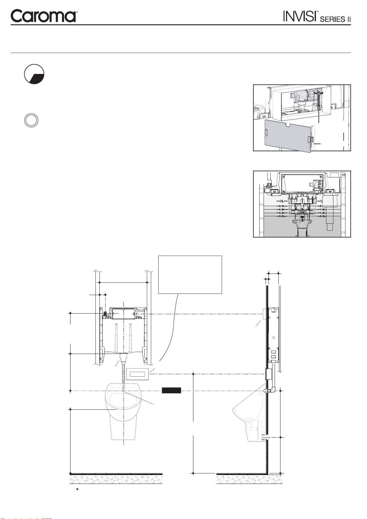
IMPORTANT - Does your urinal flush for more than 20 seconds?
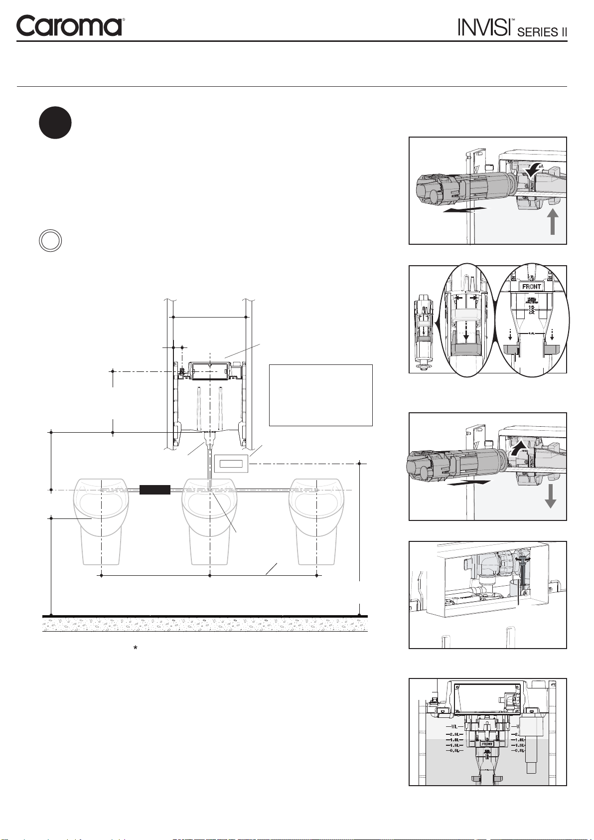
Cistern Service Access Options
Direct Panel Mounting
This is suitable for use with any
of the button panel kits.
Requires a 5mm minimum -
45mm maximum cladding
thickness.
Access to the cistern internals
is provided through the panel
window.
Remote Panel Mounting
This is suitable for use with any
of the button panel kits.
Suits up to 45mm cladding
thickness.
A Blanking Panel is required
for inwall access to cistern
internals.
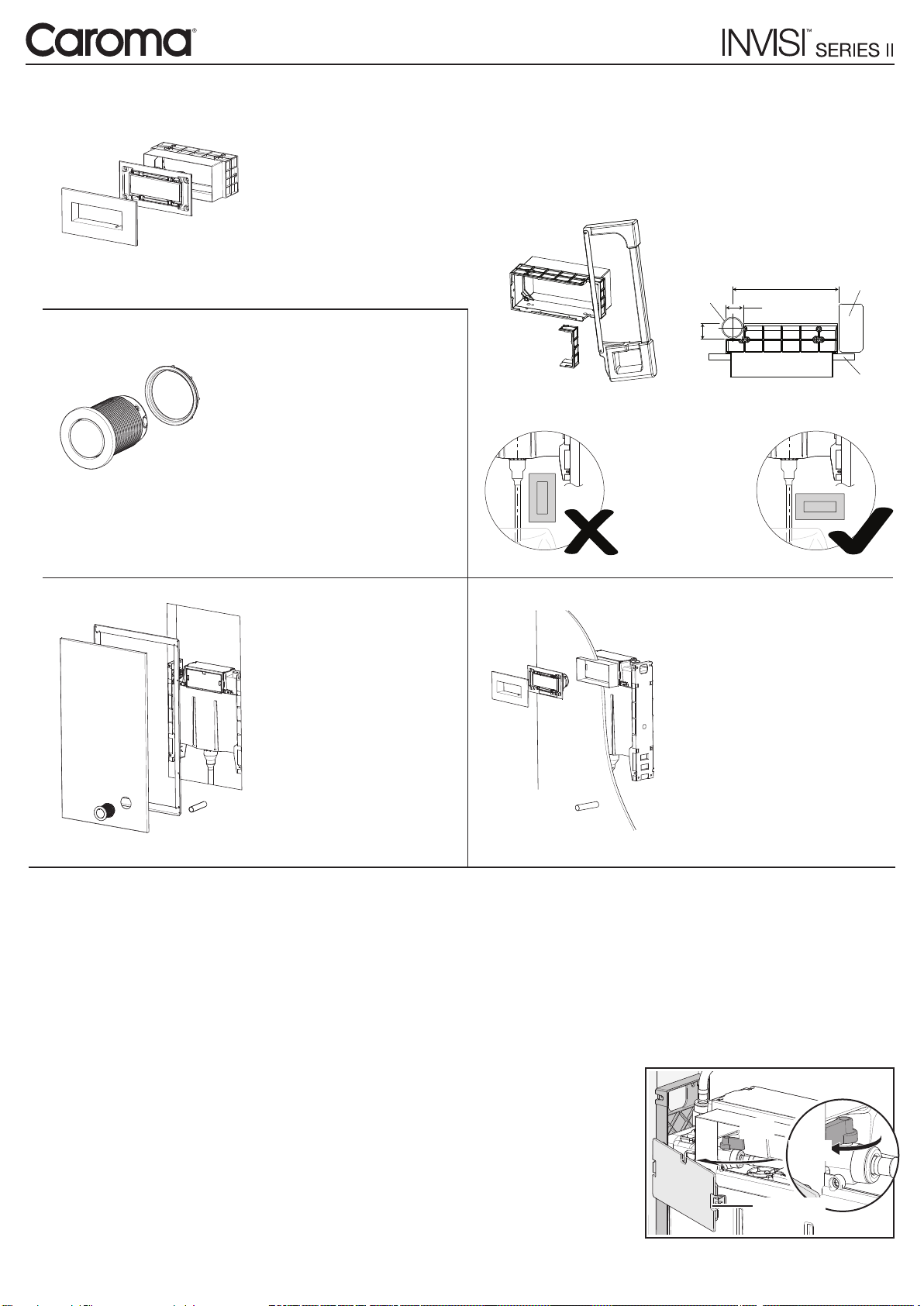
Remote Button Mounting
Access to the rear of the buttons
must be provided for servicing.
Suitable for mounting through
panels up to 55mm thick.
A Blanking Panel is required for
inwall access to cistern internals.
Large Button Panel
Used in combination with Round
Remote Buttons allows access to
the whole cistern.
With some urinal types it is possible for the discharge rate to be slower than the rell rate. When the cistern is
ushed, the water level will begin to fall until the inlet valve opens. When water is added faster than it can leave,
the cistern never empties (the outlet valve remains open and the cistern runs on).
The ush volume required for each urinal stall is 1.5 - 2.5 litres. This amount of water passes relatively slowly
through the spreader system of some urinals, (as slow as 2 litres/min) which is normally slower than the
cistern rell rate. If a urinal installer does not consider this issue it is possible that cistern run-on will occur.
There are a number of checks to ensure that the urinal operates correctly:
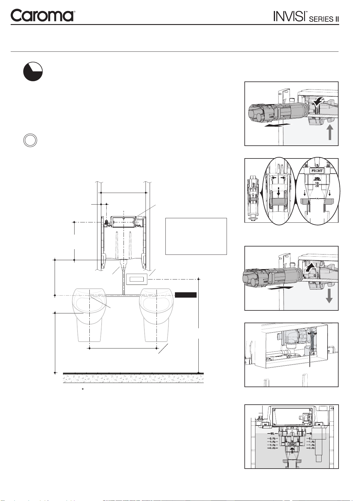
1. Ensure that the ush volume is correctly adjusted
for the installation.
2. Where the urinal ushes for more than 20 seconds,
the inlet valve ow rate must be reduced. This is
achieved by carefully adjusting the Isolating Tap
to restrict the incoming ow.
3. Flush urinal several times to conrm settings.
NOTE: In some instances, particularly single stall
urinals, it maybe necessary to adjust the Isolation
Taps ow rate down very low (almost to the off position).
OFF
ON
Dust Cover
INSTALLATION NOTE:
When installing between the copper pipe and the wall frame you
may need to modify the Remote Mounting Box for
optimum tment.
Using a hacksaw cut away the
corner adjacent to the pipe
WARNING:
Do not install the
Remote Mounting
Box vertically