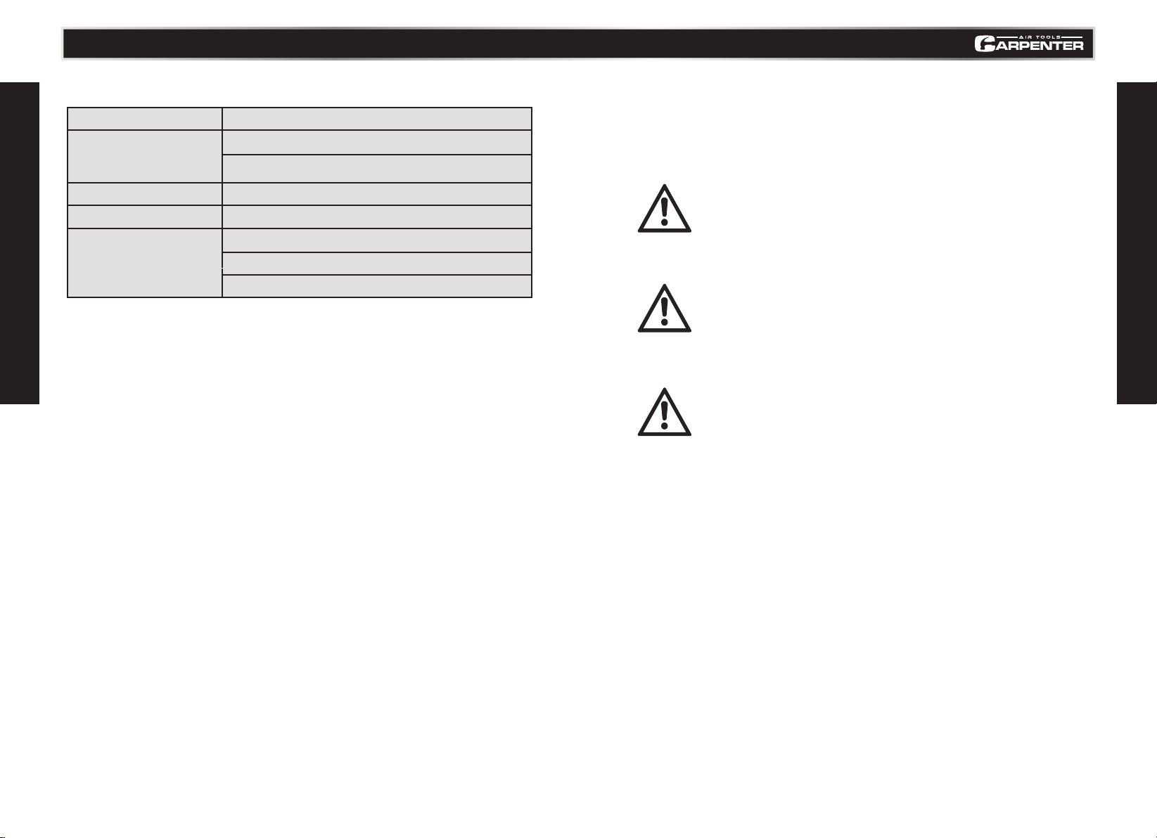
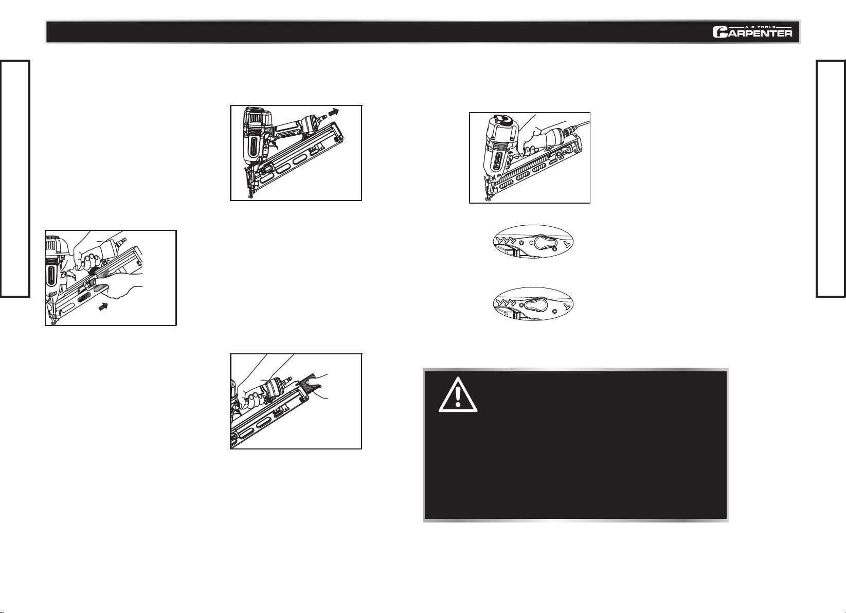
Carpenter MFG C1565 User manual

Model No. C1565
http://www.carpenterpowertools.com
15 GAUGE
FINISH NAILER

3
TABLE OF CONTENTS
TECHNICAL SPECIFICATIONS
SAFETY GUIDELINES
KEY PARTS DIAGRAM
TECHNICAL INFORMATION
TYPES OF NAILS
OPERATING INSTRUCTIONS
TROUBLESHOOTING
EXPLODED VIEW
PARTS LIST
4
5
8
9
10
11
17
18
19
TABLE OF CONTENTS

54
TECHNICAL SPECIFICATIONS
SAFETY GUIDELINES
Model No. C1565 contact us 1-888-666-1887
Operating pressure
Dimensions
(Length*Height*Width)
Net Weight
Nail capacity
Air consumptio
PERSONAL SAFETY
These precautions are intended for the personal safety of the user and others working
with the user. Please take time to read and understand them.
Make sure you read and understand this manual before using this tool. Make sure other
users read and understand this manual before they use the tool.
SAFETY GUIDELINES
This manual contains information that relates to PROTECTING PERSONAL SAFETY and
PREVENTING EQUIPMENT PROBLEMS. It is very important to read this manual carefully
and understand it thoroughly before using the product. The symbols listed below are used to
indicate this information.
70–120 psi (4.9–8.3 bar; 5– 8.5 kgf/cm²)
13-1/2"(L)x12"(H)x3-1/4"(W)
(344mmx304mmx82mm )
4.41 lbs (2.0 kg)
100 PCS
.045 ft3/cycle at 100 psi
(1.3 ltr/cycle at 6.9 bar)
(1.3 ltr/cycle at 7 kgf/cm²)
DANGER!
Potential hazard that could result in serious
personal injury including possible death.
WARNING!
Potential hazard that could result in serious
personal injury to the tool user or others in the
work area.
CAUTION!
Potential hazard that could result in damage
to the tool or property.

76
WARNING!
Potential hazard that could result in serious personal injury to
the tool user or others in the work area.
• Always wear eye and hearing protection when using the air compressor. Failure
to do so may result in sight or hearing loss.
• Do not overload the tool. Allow the tool to operate at its optimum speed for
maximum efciency.
• Do not point the tool towards yourself or other people, even when the tool has
stopped. Keep hands, feet, and all other parts of the body clear from work area.
• Do not attempt to clear nailer jams while the air hose is connected.
• Do not keep the trigger or the Push Lever pressed while loading nails.
SAFETY GUIDELINES
SAFETY GUIDELINES
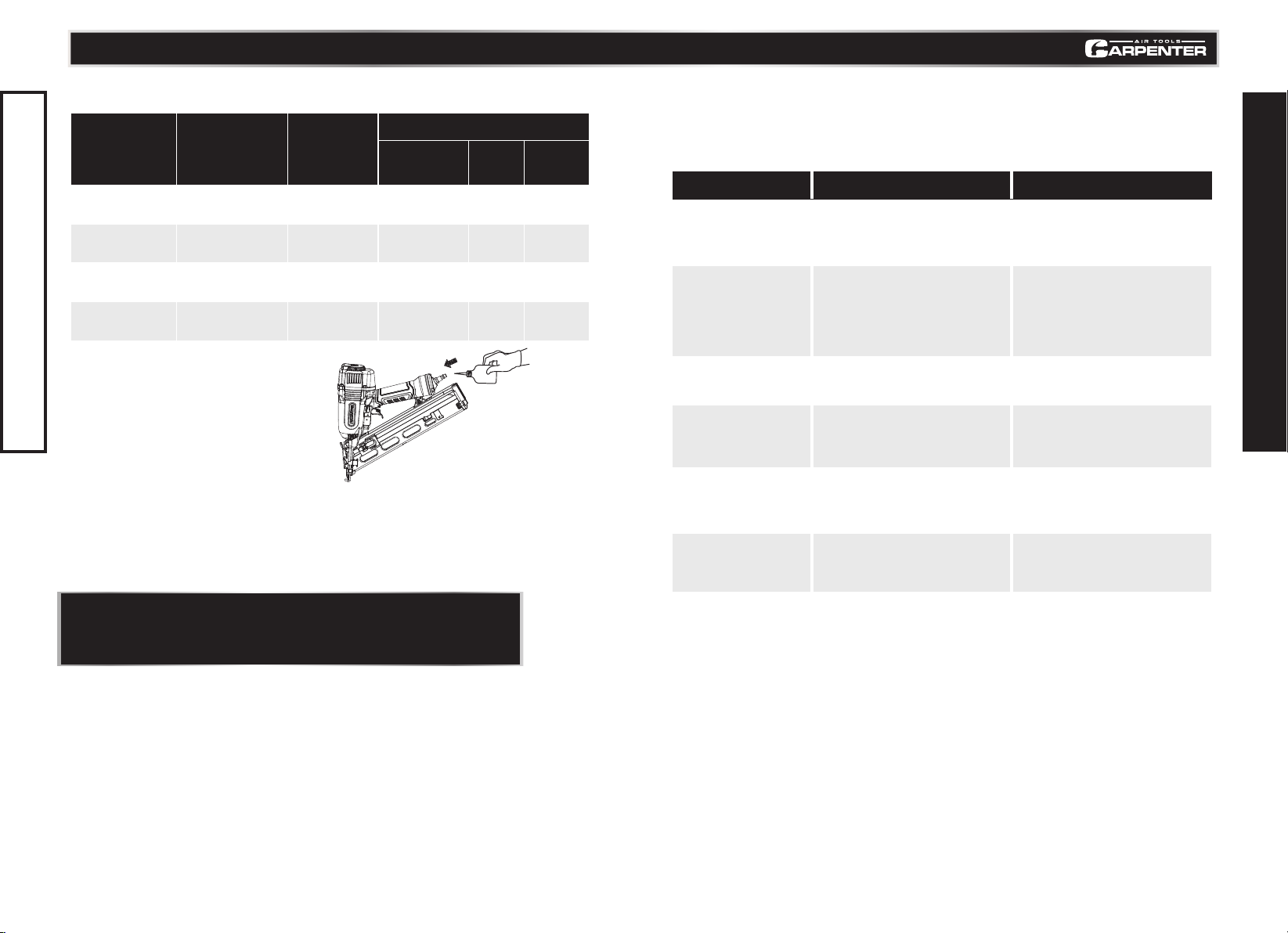
NOTE: Some commercial air line drying liquids are harmful to “O” rings and seals—
Do not use these low temperature air dryers without checking compatibility.
SAFETY GUIDELINES
CAUTION!
• DANGER! Potential hazard that could result in serious personal
injury including possible death.
• Do not use oxygen or any other combustible or bottled gas to
power air-powered tools. Failure to observe this warning can
cause explosion and serious personal injury or death.
• Do not use this tool in the presence of flammable liquids, dust or gases. Sparks that
are created during use may ignite these materials.
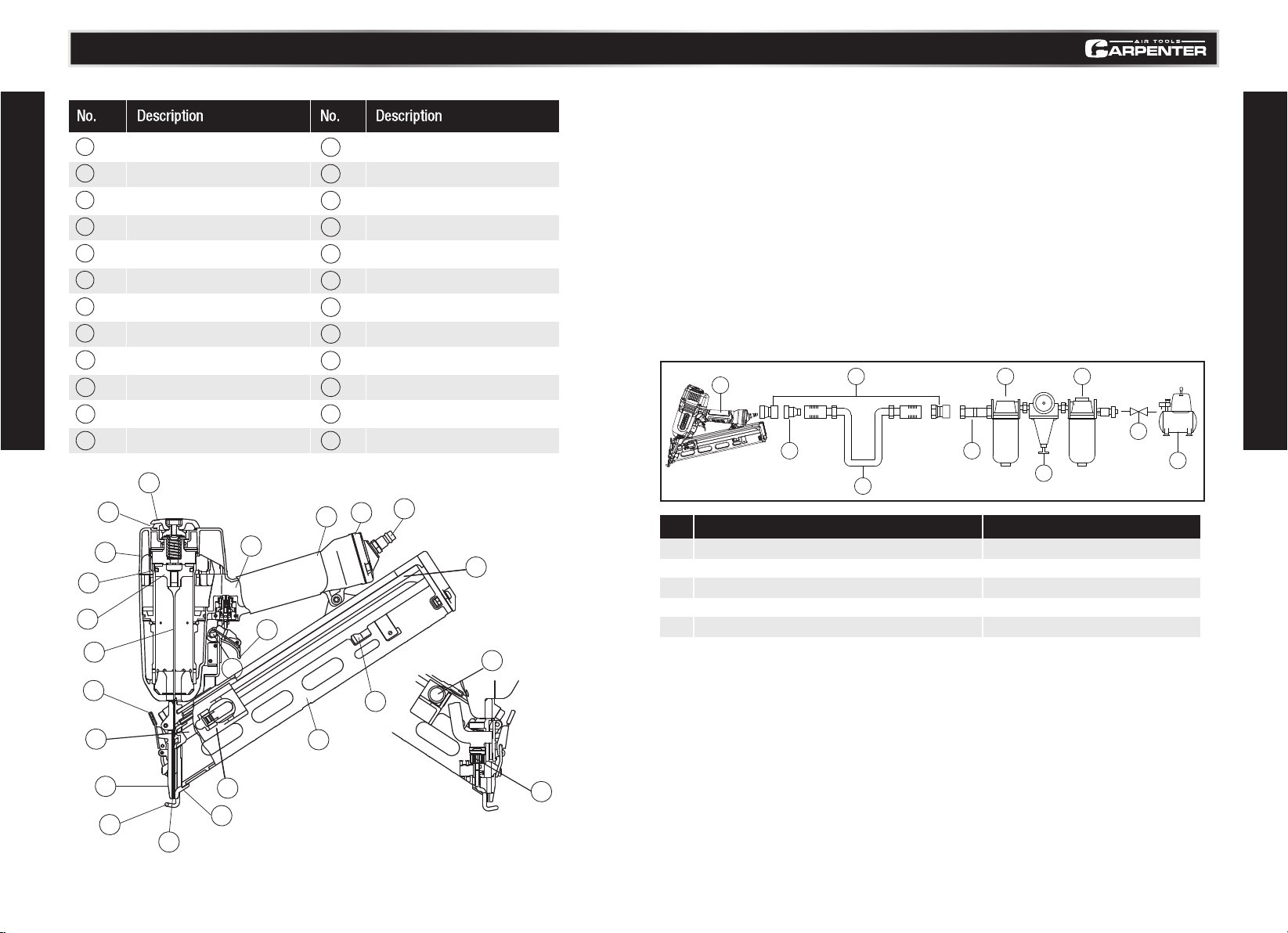
• Use only compressed air to power air-powered tools. Use an approved air hose with
a minimum length of 25' (7.6 m).
• Do not allow inexperienced or untrained individuals to operate any air-powered tool.
• Keep hands and other parts of the body away from the Outlet (Firing Head) during use.
• Nails or objects in the workpiece can cause serious injury if they are deflected by the
workpiece.
• Keep children away from the work area. Do not allow children to handle power tools.
• Never point nailer toward yourself or anyone else.
• Always assume the nailer contains fasteners. Never point the nailer toward yourself or
anyone else, whether it contains fasteners or not. If fasteners are mistakenly driven, it
can lead to severe injuries. Never engage in horseplay with the nailer. Respect the nailer
as a dangerous working implement.
• Disconnect the tool from the air supply and turn off the
compressor before performing any maintenance, when the
tool is not in use, when it is being handed to another person,
when it is left unattended, or when loading and changing
nails. Failure to comply may result in injury or damage to
equipment.
• Do not exceed the maximum or minimum pressures.
Operating the tool at the wrong pressure (too low or
too high) may cause excessive noise or rapid wear.
• Use only Non-Detergent Air Tool Lubricating Oil for this tool.
• Near and below freezing, moisture in the air line may freeze and prevent tool
operation. Do not store in a cold weather environment to prevent frost or ice
formation. Frost and ice on the tools operating valves and mechanisms could
cause tool failure.
Potential hazard that could result in damage to the tool or property.
Model No. C1565 contact us 1-888-666-1887

1
15 Gauge finish Nailer
6
Regulator
2
Quick connector
7
Filter
3
Quick coupler
8
Cut -off valve
4
Air hose
9
Air compressor
5
Lubricator
98
COMPATIBLE COMPRESSORS
GUIDELINES FOR PROPER USE AND OPERATION
Be sure to use a proper air compressor with CARPENTER Air Tools. The compressor should be able
to supply a minimal air delivery of 4.7 CFM @ 90 PSI to ensure the compressor can run continuously
with the CARPENTER 15 Gauge finish Nailer.
GENERAL USE
No. Description No. Description
The C1565 is ideal finish nailer for interior trim,exterior trim,baseboards,crown molding,window and
door casings,chair rails and so on, it accepts 15-gauge nails from 1-1/4" up to 2-1/2" in length.The
tool is lightweight and durable, stands up to the elements and provides consistently accurate results
over the life of the tool. An ideal tool for a variety of construction projects, including installation of
asphalt roofing shingles and insulation boards. It also features a high-capacity side-load magazine,
tool-less depth adjustment, durable construction, and more.
•It is recommended that a filter-regulator-lubricator be used and be located as close to the tool
•If a filter-regulator-lubricator is not installed, place up to 6 drops of compressor oil into the air
inlet plug before each use.
•If a filter-regulator-lubricator is installed, keep the air filter clean. A dirty filter will reduce the
air pressure to the tool, which will cause a reduction in power, efficiency, and general
•Verify that all of the connections in the air supply system are sealed in order to prevent air leakage.
Read and follow all the safety instructions at the beginning of this manual and inspect the
air-powered nailer prior to each use in order to ensure that the proper power source is being used
and verify that the tool is in proper working order
Model No. C1565 contact us 1-888-666-1887
KEY PARTS DIAGRAM
TECHNICAL INFORMATION
1
1
2
2
3
3
4
4
5
5
6
6
7
7
8
8
9
9
10
10
11
11
12
12
13
13
22
22
15
15
16
16
14
14
17
17
18
18
19
19
20
20
23
23
24
24
21
21
Top Cover
Air Outlet
Exhaut Cover
Piston O-ring
Piston
Driver Blade
Lock Lever
Nail Feeder(A)
Guide Plate(A)
Push Lever
Outlet(Firing Head)
Blade Guide
Nail Feeder(B)
Valve part
Switching Device
Trigger
Body
Cap
Air Plug
Nail Rail
Nail Stopper
Magazine
Ribbon Spring
Adjuster
125 7
3
4
3
6
8
9

1110
ACCEPTABLE NAILS LOADING NAILS
STANDARD ACCESSORIES
Only nails shown in the Table below can be driven with this Nailer.
Safety glasses
Allen wrench for M6 screw
Allen wrench for M5 screw
Nose cap
1
2
3
4
1
1
1
1
Model No. C1565 contact us 1-888-666-1887
TYPES OF NAILS
OPERATING INSTRUCTIONS
15 Gauge finish nails Min. Max.
3.Pull the nail feeder(B) back to engage the
nail feeder(A) to the nail strip (Fig.A).
1.Insert nail strip into rear of magazine (Fig.A).
2.Slide the nail strip forward in the magazine.
The nail strip should pass the nail stopper (Fig.B).
Magazine
Nail Stopper
Fig. A
Fig. C
Fig. B
Nail Feeder (A)
Nail Feeder (B)
1 2 3 4

1312
Model No. C1565 contact us 1-888-666-1887
OPERATING INSTRUCTIONS
REMOVING NAILS
3.Remove the remainning nails from the
magazine (Fig.F).
1.Disconnect Air hose (Fig.D).
2.Depress the nail feeder and slowly slide
the nail feeder forward (Fig.E).
Fig. D
Fig. F
Fig. E
DANGER!
●Do not drive nails on top of other nails or with nailer at too steep an angle.
Nails can ricochet and seriously injure someone.
●In order to avoid double ring or unwanted ejection of a nail due to
bouncing of the nailer, do not push nailer on workpiece to avoid recoil.
Recoil is necessary for proper operation of the nailer.
●Do not drive nails from both sides of a wall at the same time. Nails can
be driven into and through the wall and hit a person on the opposite side.
●Never drive nails into thin boards or near corners and edges of workpiece.
Nails can be driven through or away from workpiece resulting in serious or
life threatening injury.
●Never use a nailer which is defective or operating abnormally.
●Never use a nailer as hammer.
METHOD OF OPERATION
The Carpenter Air-powered Brad Nailer is equipped with a push lever at the nailing point and will not
operate unless the push lever is depressed (pushed upwards)(Fig.G).
Fig. G
①Single Actuation Mechanism
1.Set the switching device to the position as (Pic I);
2.Make sure the push lever position to the workpiece,Pull the
gunbody and keep the push lever connect to the workpiece and
then press the trigger,It start to work;
3.After the rst nails re,loosen the trigger and raise up the
gunbody,Position the push lever to the workpiece and rework as
above steps.
②Contact Actuation Mechanism
1.Set the switching device to the position as (Pic II);
2.Press the trigger rst and then postition the push lever to the
workpiece,Press the push lever and begin to re;
3.After the rst nails out, hold the trigger tight,and raise up the push
lever,Make sure the push lever postion to the workpiece,and then
press it and rework as above steps.
Pic I
Pic II

1514
Model No. C1565 contact us 1-888-666-1887
OPERATING INSTRUCTIONS
TROUBLESHOOTING
Fig. H
Fig. J Fig. K
ADJUSTING THE NAILING DEPTH
To assure that each nail penetrates to the same depth, be sure that:
① The air pressure to the Nailer remains constant (regulator is installed and working properly).
②The nailer is always held rmly against the workpiece. If nails are driven too deep or too shallow into the
workpiece, adjust the nailing depth using the following instructions.
1.Disconnect air hose from nailer (Fig. H).
2a. If the nails are driven too deep, pull the adjuster
downward and turn counter-clockwise (Fig. J).
2b. If nails are driven too shallow, pull the adjuster
downward and turn clockwise (Fig. K).
3. Connect the air hose and perform a nailing test. ALWAYS WEAR EYE PROTECTION.
4. If additional adjustments are necessary, DISCONNECT AIR HOSE FROM NAILER and repeat step 2.
Disconnect air hose
1.Open the guide (Fig.L).
2.Remove the jammed nails with a slotted-head
screwdriver (Fig.M).
Fig. M
Fig. L

1716
Model No. C1565 contact us 1-888-666-1887
OPERATING INSTRUCTIONS
TROUBLESHOOTING
Note: Solvent sprayed on the nose to clean and free up the push lever
may have the opposite effect.The solvent may soften the tar on the
shingles and cause tar buildup to be accelerated.Dry operation is better.
• Lubrication: If the air-powered nish nailer
and the compressor are not equipped with
an in-line lubrication system, place up to
6 drops of pneumatic tool oil into the air
inlet before each work day or after every 2
hours of continuous use, depending on the
characteristics of the workpiece and type
of fasteners used.
• Air-operated tools must be inspected periodically and worn or broken parts must be
replaced to ensure that the tools are operating safely and efciently.
• Inspect and replace worn or damaged O-rings, seals, etc. Tighten all screws and caps
frequently in order to help prevent personal injury.
• Keep the magazine of the tool clean and free of any dirt or abrasive particles.
MAINTENANCE
None
X X
X
See below X
MAINTENANCE
REQUIRED
TOOLS OR
MATERIALS
REQUIRED
DESCRIPTION Each Use or
Every 2 Hrs
MAXIMUM SERVICE INTERVAL
Monthly As
Needed
General inspection-
free movement
In-depth inspection
Replace worn or
broken parts
Lubrication
Adjusting screw assembly
Movable magazine
Worn or broken
parts
Pneumatic tool
oil
X
TROUBLESHOOTING
Most minor problems can be resolved quickly and easily using the table below.
If problems persist,contact a Carpenter for assistance.
SYMPTOM
PROBLEM
SOLUTIONS
Nailer operates,but no
nail is driven.
1. Check for a jam.
2. Nail feeder damaged?
3. Ribbon spring weakend or damaged?
4. Check for proper nails.
1.Clear a jam per page 18.
2. Replace nail feeder.
3. Replace ribbon spring.
4. Use only recommended nails.
Weak drive.
Slow to cycle.
1. Check air pressure.
2. Check position of nailing depth
adjustment adjuster.
3. ------
4. Driver blade worn
5. Piston O-ring worn or damaged?
1. Increase air pressure.(Do not
exceed 120 psi(8.3bar 8.5kg/cm²)
2. Readjust per page 15.
3. Use Hitachi pneumatic tool lubricant.
4.Contact Hitachi for replacement.
5.Contact Hitachi for replacement.
Drives too deep.
1. Check air pressure.
2. Check position of nailing depth
adjustment guide plate (A)
1. Reduce air pressure.(Adjust 70-120psi)
(4.9-8.3bar 5-8.5kg/cm²)
2. Readjust per page 15.
Skipping nails.
Intermittent feed.
1. Check for proper nails.
2. ------
3. Nail feeder damaged?
4. Ribbon spring weakend or damaged?
1. Use only recommended nails.
2. Lubricate the nail rail per page18.
3. Replace nail feeder.
4. Replace ribbon spring.
Nails jam Driven nail is
bent.
1. Piston O-ring worn or damaged?
2. Check for proper nails.
3. ------
4. Driver blade worn?
1. Contact Hitachi for replacement.
2. Use only recommended nails.
3. Lubricate the nail rail per page18.
4. Contact Hitachi for replacement.
Drives properly during
normal operation,but does
not drive fully at faster
nailing speeds.
1. Check inside diameter of air hose. 1. Use larger air hose.

1918
Model No. C1565 contact us 1-888-666-1887
EXPLODED VIEW
PARTS LIST
1
2
3
4
5
6
7
8
9
10
11
12
13
14
15
16
17
18
19
20
21
22
23
24
25
26
27
28
29
30
31
32
33
34
35
36
37
38
39
40
Hex bolt M6X12
Plate
Air exhauster
Hex bolt M5X20
Exhaust cover
Gasket
Washer
Head Valve Spring
O-ring 20.4X2.4
Head valve
Cylinder
O-ring 46X2
Collar
O-ring 56X2.4
O-ring 45X3.55
O-ring 34.5X3.55
Main piston
Bumper
Washer
Shift lever
Gunbody
Mixed plate
Hex bolt M6X30
Movable Plate
Roll pin 4x14
Guide Plate
Roll pin 3x20
Spring
Locked nut M5
Safety shelf
Driver head
Steelball Dw=2
Spring
Adjustable Nut
Safety tip
Safety sleeve
O-ring 14X1.8
O-ring 20X1.8
Valve bushing
O-ring 6.1X1.8
1
1
1
5
1
1
1
1
1
1
1
1
1
1
1
1
1
1
1
1
1
1
2
1
1
1
1
1
4
1
1
1
1
1
1
1
2
1
1
1
41
42
43
44
45
46
47
48
49
50
51
52
53
54
55
56
57
58
59
60
61
62
63
64
65
66
67
68
69
70
71
72
77
74
75
76
77
78
79
O-ring 6.4X2
O-ring 9X1.8
Sleeve
Switch Spring
O-ring 2.4X1.6
Valve plunger
Valve bushing
Roll pin 3x22
Roll pin 3x20
Trigger
Safety shield
Roll pin 3x16
Guide seat
Roll pin 3x35
Steelball Dw=4
Spring
Shift knob
Roll pin 3x10
Coil Spring
Roll pin 2.5x20
Hex bolt M5X16
Washer d=5
Magazine cover
Nail Rail
Pusher seat
Nail Stopper
Pusher
Spring
Nail groove
Sleeve
Handle Sleeve
End Cap
Washer
1/4 NPT18 Air inlet plug
Air plug
Block
Hex wrench M5/4mm
Hex wrench M6/5mm
Oil pot
1
1
1
1
2
1
1
1
2
1
1
1
1
1
1
1
1
1
1
1
5
3
1
1
1
1
1
1
1
1
1
1
1
1
1
1
1
1
1
1
2
3
4
5
6
7
8
9
10
11
12
13
14
15
16
17
18
19
20
21
22
23
24
26
30
31
32
25
29
34
33
35
36
48
49
51
49
52
53
50
37
37
38
39
40
41
42
43
44
45
45
46
55
56
57
297072
73
61
59
63
64
65
67
68
66
29
27
28
74
60
777879
62
58
61
62
04
47
54
71
69
61
75
76
Table of contents
Other Carpenter MFG Nail Gun manuals
Popular Nail Gun manuals by other brands

Powernail
Powernail 445FS Operation and maintenance manual

Bostitch
Bostitch RN45B Operation and maintenance manual

Dynadie
Dynadie 12252 Operating, maintenance and safety instructions

Milwaukee
Milwaukee C12 PN Original instructions

Makita
Makita GN900 instruction manual

Paslode
Paslode CF-325 operating manual