manuals.online logo
Brands
  1. Home
  2. •
  3. Brands
  4. •
  5. Carrier
  6. •
  7. Heat Pump
  8. •
  9. Carrier Infinity 50DT User manual

Carrier Infinity 50DT User manual

Other manuals for Infinity 50DT

1

This manual suits for next models

6

Other Carrier Heat Pump manuals

Carrier 38HDV009 Dimensions and installation guide

Carrier

Carrier 38HDV009 Dimensions and installation guide

Carrier 50HX Guide User manual

Carrier

Carrier 50HX Guide User manual

Carrier 12K User manual

Carrier

Carrier 12K User manual

Carrier 50ZHA Assembly Instructions

Carrier

Carrier 50ZHA Assembly Instructions

Carrier AquaSnap 30AWH-R User manual

Carrier

Carrier AquaSnap 30AWH-R User manual

Carrier 50SZ Series Dimensions and installation guide

Carrier

Carrier 50SZ Series Dimensions and installation guide

Carrier 38YSA Instructions and recipes

Carrier

Carrier 38YSA Instructions and recipes

Carrier AquaSnap Touch Pilot Junior Series Manual

Carrier

Carrier AquaSnap Touch Pilot Junior Series Manual

Carrier 30ZQ024-G Installation manual

Carrier

Carrier 30ZQ024-G Installation manual

Carrier AquaSnap 61CG-A Manual

Carrier

Carrier AquaSnap 61CG-A Manual

Carrier 50FCQ 04-07 Series Installation and user guide

Carrier

Carrier 50FCQ 04-07 Series Installation and user guide

Carrier 38BYG Series Operation manual

Carrier

Carrier 38BYG Series Operation manual

Carrier 50HQ Dimensions and installation guide

Carrier

Carrier 50HQ Dimensions and installation guide

Carrier PTV Dimensions and installation guide

Carrier

Carrier PTV Dimensions and installation guide

Carrier WSHP Open v3 Quick setup guide

Carrier

Carrier WSHP Open v3 Quick setup guide

Carrier 50ZH Series Assembly Instructions

Carrier

Carrier 50ZH Series Assembly Instructions

Carrier 42n User manual

Carrier

Carrier 42n User manual

Carrier COMFORT 25HCS User manual

Carrier

Carrier COMFORT 25HCS User manual

Carrier 38YSA Instructions and recipes

Carrier

Carrier 38YSA Instructions and recipes

Carrier 38CQ Dimensions and installation guide

Carrier

Carrier 38CQ Dimensions and installation guide

Carrier 50TCQD17-D24 Installation and user guide

Carrier

Carrier 50TCQD17-D24 Installation and user guide

Carrier 38AQ024 Dimensions and installation guide

Carrier

Carrier 38AQ024 Dimensions and installation guide

Carrier WEATHERMASTER 50HJQ016 Dimensions and installation guide

Carrier

Carrier WEATHERMASTER 50HJQ016 Dimensions and installation guide

Carrier Bryant Evolution Extreme 186CNV User manual

Carrier

Carrier Bryant Evolution Extreme 186CNV User manual

Popular Heat Pump manuals by other brands

Daikin RXL12QMVJU Service manual

Daikin

Daikin RXL12QMVJU Service manual

AIREDALE BluCube CUR092V16-1CO-0 Installation and maintenance manual

AIREDALE

AIREDALE BluCube CUR092V16-1CO-0 Installation and maintenance manual

Calyenty RBH 125 Customer's manual

Calyenty

Calyenty RBH 125 Customer's manual

GRE HPGI50 owner's manual

GRE

GRE HPGI50 owner's manual

Hayward SUMHEAT HP5131DT3 Installation instructions manual

Hayward

Hayward SUMHEAT HP5131DT3 Installation instructions manual

REMKO SQW 400 Electrical wiring

REMKO

REMKO SQW 400 Electrical wiring

Sanyo SAP120FCH Service manual

Sanyo

Sanyo SAP120FCH Service manual

Daikin EHYHBH05AA Operation manual

Daikin

Daikin EHYHBH05AA Operation manual

Panasonic WH-SDF03E3E5 Design handbook

Panasonic

Panasonic WH-SDF03E3E5 Design handbook

Airxcel 45000 Series Installation, operation and maintenance instructions

Airxcel

Airxcel 45000 Series Installation, operation and maintenance instructions

Mitsubishi Electric PUZ-SWM60VAA Service manual

Mitsubishi Electric

Mitsubishi Electric PUZ-SWM60VAA Service manual

Dimplex LI 16I-TUR Installation and operating instruction

Dimplex

Dimplex LI 16I-TUR Installation and operating instruction

Mitsubishi Electric EHSE-YM9EC Service manual

Mitsubishi Electric

Mitsubishi Electric EHSE-YM9EC Service manual

TGM CTV14CN018A Technical manual

TGM

TGM CTV14CN018A Technical manual

Kokido K2O K880BX/EU Owner's manual & installation guide

Kokido

Kokido K2O K880BX/EU Owner's manual & installation guide

Viessmann VITOCAL 300-G PRO Type BW 2150 Installation and service instructions

Viessmann

Viessmann VITOCAL 300-G PRO Type BW 2150 Installation and service instructions

Viessmann KWT Vitocal 350-G Pro Series Installation and service instructions for contractors

Viessmann

Viessmann KWT Vitocal 350-G Pro Series Installation and service instructions for contractors

Weishaupt WWP L 7 Installation and operating instruction

Weishaupt

Weishaupt WWP L 7 Installation and operating instruction

manuals.online logo
manuals.online logoBrands
  • About & Mission
  • Contact us
  • Privacy Policy
  • Terms and Conditions

Copyright 2025 Manuals.Online. All Rights Reserved.

Turn to the Expertg
Installation Instructions
IMPORTANT: OAT sensor must be field installed. See
Accessory Installation for more details.
IMPORTANT: This Infinity _unit is designed for use with an
Infinity User Interface.
NOTE: Read the entire instruction manual before starting the
installation.
TABLE OF CONTENTS
Page
SAFETY CONSIDERATIONS ........................ 2
INTRODUCTION .................................. 2
RECEIVING AND INSTALLATION ................ 2-10
Check Equipment ................................. 2
Identify Unit ................................... 2
Inspect Shipment ................................ 2
Provide Unit Support .............................. 2
Roof Curb ..................................... 2
Slab Mount .................................... 2
Ground Mount ................................. 2
Provide Clearances ................................ 6
Rig and Place Unit ................................ 6
Inspection ..................................... 6
Introduction .................................... 6
Use of Rigging Bracket ........................... 6
Select and Install Ductwork .......................... 7
Converting Horizontal Discharge Units to Downflow
(Vertical) Discharge Units ......................... 8
Provide for Condensate Disposal ..................... 8
Install Electrical Connections ........................ 8
High-Voltage Connections ........................ 8
Routing Power Leads Into Unit .................... 10
Connecting Ground Lead to Ground Screw .......... 10
Routing Control Power Wires .................... 10
Accessory Installation ........................... 10
Special Procedures for 208-v Operation ............. 10
PRE-START-UP .................................. 12
START-UP .................................... 12-21
Unit Start-Up ................................ 12-16
Sequence of Operation ......................... 16-19
Check for Refrigerant Leaks ........................ 19
Start-Up Adjustments ............................. 19
Checking Cooling and Heating Control Operation ..... 19
Checking and Adjusting Refrigerant Charge .......... 19
Refrigerant Charge ............................. 19
No Charge .................................... 19
Low Charge Cooling ............................ 19
To Use Cooling Charging Charts ................... 19
Indoor Airflow and Airflow Adjustments ............ 19
Non-Communicating Emergency Cooling/Heating Mode . 19
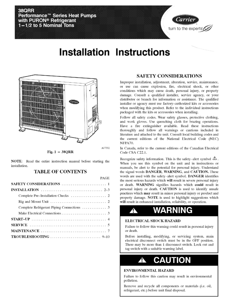
Fig. 1 - Unit 50DT
C99001
MAINTENANCE ............................... 21-24
Air Filter ....................................... 22
Indoor Fan and Motor ............................. 22
Outdoor Coil. Indoor Coil, and Condensate Drain Pan .... 22
Outdoor Fan .................................... 22
Electrical Controls and Wiring ...................... 22
Refrigerant Circuit ................................ 22
Indoor Airflow . ................................. 22
Metering Devices-TXV & AccuRater Piston .......... 23
Pressure Switches ................................ 23
Loss-of-Charge Switch ........................... 23
High-Pressure Switches ........................... 23
Copeland Scroll Compressor (Puron ®:Refrigerant) ....... 23
Refrigerant System ............................... 23
Refrigerant ................................... 23
Compressor Oil ................................ 23
Servicing Systems on Roofs with Synthetic Materials ... 23
Liquid-Line Filter Drier ......................... 23
Puron (R-410A) Refrigerant Charging .............. 23
TROUBLESHOOTING ............................. 24
FINAL CHECKS .................................. 25
CARE AND MAINTENANCE ....................... 25
START-UP CHECKLIST ........................... 29
SAFETYCONSIDERATIONS
Installationandservicingofthisequipmentcanbehazardousdueto
mechanicalandelectricalcomponents.Onlytrainedandqualified
personnelshouldinstall,repair,orservicethisequipment.
Untrainedpersonnelcanperformbasicmaintenancefunctionssuch
ascleaningandreplacingairfilters.Allotheroperationsmustbe
performedbytrainedservicepersonnel.Whenworkingonthis
equipment,observeprecautionsintheliterature,ontags,andon
labelsattachedtoorshippedwiththeunitandothersafety
precautionsthatmayapply.
Followallsafetycodes.Installationmustbeincompliancewith
localandnationalbuildingcodes.Wearsafetyglasses,protective
clothing,andworkgloves.Havefireextinguisheravailable.Read
theseinstructionsthoroughlyandfollowallwarningsorcautions
includedinliteratureandattachedtotheunit.
Recognizesafetyinformation.Thisisthesafety-alertsymbol'_.
Whenyouseethissymbolontheunitandininstructionsormanuals,
bealerttothepotentialforpersonalinjury.Understandthesesignal
words:DANGER.WARNING,andCAUTION.Thesewordsare
usedwiththesafety-alertsymbol.DANGERidentifiesthemostse-
rioushazardswhichwillresultinseverepersonalinjuryordeath.
WARNINGsignifieshazardswhichcouldresultinpersonalinjury
ordeath.CAUTIONisusedtoidentifyunsafepracticeswhichmay
resultinminorpersonalinjuryorproductandpropertydamage.
NOTEisusedtohighlightsuggestionswhichwillresultinen-
hancedinstallation,reliability,oroperation.
ELECTRICALSHOCKHAZARD
Failuretofollowthiswarningcouldresultinpersonalinjury
ordeath.
Beforeinstallingorservicingsystem,alwaysturnoffmain
powertosystem.Theremaybemorethanonedisconnect
switch.Turnoffaccessoryheaterpowerswitchifapplicable.
UNITOPERATIONANDSAFETYHAZARD
Failuretofollowthiswarningcouldresultinpersonalinjury
orequipmentdamage.
Puron(R-410A)systemsoperateathigherpressuresthan
standardR-22systems.DONOTuseR-22service
equipmentorcomponentsonPurnn(R-410A)equipment.
EnsureserviceequipmentisratedforPuron(R-410A).
INSPECTSHIPMENT
Inspectforshippingdamagewhileunitisstillonshippingpallet.If
unitappearstobedamagedoristornloosefromitsanchorage,have
itexaminedbytransportationinspectorsbeforeremoval.Forward
claimpapersdirectlytotransportationcompany.Manufactureris
notresponsibleforanydamageincurredintransit.Checkallitems
againstshippinglist.ImmediatelynotifythenearestCarrieroffice
ifanyitemismissing.Topreventlossordamage,leaveallpartsin
originalpackagesuntilinstallation.
Step2--ProvideUnitSupport
Forhurricanetiedowns,contactdistributorfordetailsandPE
(ProfessionalEngineering)Certificate,ifrequired.
ROOFCURB
Installaccessoryroofcurbinaccordancewithinstructionsshipped
withcurb(SeeFig.4).Installinsulation,cantstrips,roofing,and
flashing.Ductworkmustbeattachedtocurb.
IMPORTANT:Thegasketingoftheunittotheroofcurbiscritical
forawatertightseal.Installgasketingmaterialsuppliedwiththe
roofcurb.Improperlyappliedgasketingalsocanresultinairleaks
andpoorunitperformance.
Curbshouldbeleveltowithin1/4in.(SeeFig.2).ThisisnecessaU
for unit drain to function properly. Refer to accessory roof curb
installation instructions for additional information as required.
B
3
MAXIMUM ALLOWABLE
DIFFERENCE (in,)
A-B B-C A-C
1/4 1/4 1/4
C99065
Fig. 2 - Unit Leveling Tolerances
SLAB MOUNT
Place the unit on a solid, level concrete pad that is a minimum of 4
in. thick with 2 in. above grade. The slab should extend
approximately 2 in. beyond the casing on all 4 sides of the unit (See
Fig. 3). Do not secure the unit to the slab except when required by
local codes.
INTRODUCTION
The 50DT packaged heat pump is fully self- contained and designed
for outdoor installation (See Fig. 1). Standard units are shipped in
a horizontal-discharge configuration for installation on a
ground-level slab or directly on the ground if local codes permit.
Standard units can be converted to downflow (vertical) discharge
configurations for rooftop applications.
RECEIVING AND INSTALLATION
Step 1--Check Equipment
IDENTIFY UNIT
The unit model number and serial number are printed on the unit
informative plate. Check this information against shipping papers.
7
EVAR COIL. COND COIL
Fig. 3- Slab Mounting Detail
C99096
GROUND MOUNT
The unit may be installed either on a slab or placed directly on the
ground if local codes permit. Place the unit on level ground prepared
with gravel for condensate discharge.
Roof Curb for Small Cabinet
Note A: When unit mounting screw is used,
retainer bracket must also be used,
Roof Curb for Large Cabinet
Note A: When unit mounting screw is used,
retainer bracket must also be used,
UNIT SIZE
024-030
036-060
E
Long
Support
Support
A
R/A
\\\\\
_Gasket around _
duct
S/A
/2
/
insulated
deck pan Gasket around
outer edge \ \
\\,\
NOTES:
ODS CATALOG A B
NUMBER IN. (MM) IN. (MM)
CPRFCURB008A00 8 (203) 11 (279)
CPRFCURB00FA00 14 (356) 11 (279)
CPRFCURB008A00 8 (203) 16-3/16 (411)
CPRFCURB009A00 14 (356) 16-3/16 (411)
[. Roof curb must be set up for unit being installed.
C
IN. (MM)
16-1/2 (419)
16-1/2 (419)
17-3/8 (441)
17-3/8 (441)
D
IN. (MM)
28-3/4 (730)
28-3/4 (730)
40-1/4 (1022)
40-1/4 (1022)
E
IN. (MM)
30-3/8 (771)
30-3/8 (771)
41-15/16 (1065)
41-15/16 (1065)
F
IN. (MM)
44-5/16 (1126)
44-5/16 (1126)
44-7/16 (1129)
44-7/16 (1129)
A05308
G
IN. (MM)
45-15/16 (1167)
45-15/16 (1167)
46 - 1/16 (1169)
46-1/16 (1169)
2. Seat strip must be applied, as required, to unit being installed.
3. Dimensions are in inches.
4. Dimension in ( )are in millimeters.
5. Roof curb is made of 16 gauge steel.
6. Attach ductwork to curb (flanges of duct rest on curb).
7. Inadated panels: I in. thick fiberglass 1 lb. density.
S. When unit mounting screw is used (see Note A). a retainer bracket must be used as well. This bracket must also be used when required by code for hurricane or seismic
conditions. This bracket is available through Micrometl.
Fig. 4 - Roof Curb Dimensions
I
=
o>
++
J,IE? ¢ _6S s ST_I i C_ .....
+"]!
4O 4
[1_ 0'1
L_ :+::o,++-+::+?,
| Fi one:| _::.+ _ -_ moP: o+A
,, +,+,j
ID ............................ C
TOP VIEW
!:::t, j ' lJ?J ':' J -" ?! : + ' ?
j ++ii i I
REQUIREDCLEARANCESTO COMBUSTIBLEMA]+- t,: N Ht::l:[ [I_]
TOP Of /_l: !55 _ r1 no
D:J'S: S:_[ OF U1:T 5O 8:2 O[']
S:S: ¢PP3S]Ti ['UC:S 355 I _ nl,:
8OT:Ot,1 OF Ut+!T :2 7 ({, _Q]
[L[¢TR:C II:AT PAI:t _1_,i :36 0_']
t,_:LL1_+I[IERS _11i
B_l_[_t_ 0/:15¸ :_O_L_ Lt_l:i_ S:8[ I06_8 t42 ,]0i
LI_Ii _t_[_ LI_,3_OLI_I[I _fr' ¸;¸ POW[R E_:_ SI[:E _1_0 i_r ,,0
LI_Ii +t_l BLOCI_ OR ,201¢tli{ _LLS _I_ OiH[R
6£O810[D 3U1_i_C15 _',3_,[R iNI_ SI_E i068 8 142 00i
_JIRED C_A_r,_ N38 OP_IATION AND _t_
i,_? CO!I _C¢_S Sil;_ gl,_ 0 t36 001
PO_£ tI:R_ S:O{ 1/_ 8 !36 ooi
[1_]: TOP _1_ 0 i_ r[,
S:_: CPPOS!T[ D[_C:S _1_ 9 [36 ,]_]
D"_ P_I_:J )O4 8 [i2 ,]0]+
+_,llt:Rt:_ _:STAI¢iS :F IjtliT IS PL_8I[, i[S8 :I+AIi 30_ 8 1i2 0[,i FR3_ _"1i
[)i,i[N ]:'[,JS i } [ i+' !P,:(H:S
40!
I
{I _5]
8e8
15 53t
PPi/
i [9 53] [_i 671 (9 831
L+ REARViEW
O?'88 '+:i?'I 5)E:T]24 'J38
+( ao[8Es: Pul,!r ,911 0]22
'JI
I
E
=
_o
i_ TTr_, _ O '_o_4_n_ _r,ITS[SCUh,r_ S _1_[r'_8_R_ 8_ C,r_ _ ¢o_'e_t_;cq
(SRR R 13 H it'c,_ Et_ .................. s ( plSt( ¢!H I!;:
40'
i600]
®
E l
l l
I
D _ :_ C
TOP VIEW
sf '_s,]; _ ] i] ] ]::s,s sTJsas
}::i }{
O6Cl 155; 753 i} 1465{ 2J 199 I]I 3
@4H ES.q0i BL0_, ELECH 1, lE_ .
,/:_,, ..... I_ _ :',,:h "s
ii IIi I i
i
LEFT SIDE VIEW
41 i/ %1 J}_ I () h[[_
?2[c 5 C _ ?
CCIT OL 4T:_ "i
2};
[3 ¢3] k
122 2 _ 5 0
[46 _
• D_ OUTLET
19 8 [(_ %] _4P ]
._,_o,0_,.,:.,' FRONT VIEW RIGHT SIDE ViEW
REI]4_IREDCLE&RANCES TO C(]{_]_JS_BLE _AI_. t,[[ bt [iS 1/41
]OF or L_MT 355 6 [14 001
0(_¢_ S/_[ ¢'_ UN]_ _ 8 12 001
S_I)_ OPPOS]!_ D_;:i8 355 6 1/4 O8)
[_O_]0'40J ¸ _1_11_ 12 _ ['3 581
ELECTRIC iI[/_T P_d_EL 8_4 4 [_. _0
REC IREQUII@DCLE_RAN_S. _,',![ [ i_,I[ TE_8 [ l _ ]
_E_¢EE[_ L_Ji]S PO_'EI_E_ ¸ $]0E .... i06_ 8 [42 0O]
8_ii _1_{)¸ J_JSRO_Nt)E[) St_ £ 8 _(}_fR E_4_R_8;_f _i4 C 156 081
U',J_ ,_1_)¸ 818'_ OI _0 '¸_ _ < #_{ 0/q_ p
RE_UIREB CLF_RAN!2E FOR OP_TIO_ ARD 51_'qlCING
E,_P COIL _CCESS .<i8[ 914 0 [36 00]
PO_[I_ _[_1i_¸ 5_E g_4 '3 156 00J
U_iT TOP _1 _ [3'3 00]
S]D[ OPP05!i[ 08¢ .< 914 '_ [ 6 00
0(_:i I_ 3O4 5 112 001_
,t,IZ[_i',l[J_,__iST_'_ES ir [Jt_iT 7S PI _C[_¸ i[SS THeft 3'34 8 []_ 00} r_oq ',_!1
S_SIEI,t i_E'_ S,Slr_ ?ERFCR_,Itd_CE_tBE :30[4PRO_IISE_
DiNI[S/ONS i [ _1::1 l[ JEHS
[/5 83]
[
REAR VIEW
g
-4
00 031 060
,_c ( @ is FU, (}] 5:02;,
ii
Step 3--Provide Clearances
The required minimum service clearances are shown in Fig. 5 and
6. Adequate ventilation and outdoor air must be provided. The
outdoor fan draws air through the outdoor coil and discharges it
through the top fan grille. Be sure that the fan discharge does not
recirculate to the outdoor coil. Do not locate the unit in either a
corner or under an overhead obstruction. The minimum clearance
under a partial overhang (such as a normal house overhang) is 48 in.
above the unit top. The maximum horizontal extension of a partial
overhang must not exceed 48 in.
IMPORTANT: Do not restrict outdoor airflow. An air restriction at
either the outdoor-air inlet or the fan discharge may be detrimental
to compressor life.
Do not place the unit where water, ice, or snow from an overhang
or roof will damage or flood the unit. Do not install the unit on
carpeting or other combustible materials. Slab-mounted units
should be at least 4 in. above the highest expected water and runoff
levels. Do not use unit if it has been under water.
Step 4--Rig and Place Unit
Rigging and handling of this equipment can be hazardous for many
reasons due to the installation location (roofs, elevated structures,
etc.).
Only trained, qualified crane operators and ground support staff
should handle and install this equipment.
When working with this equipment, observe precautions in the
literature, on tags, stickers, and labels attached to the equipment, and
any other safety precautions that might apply.
Training for operators of the lifting equipment should include, but
not be limited to. the following:
1. Application of the lifter to the load, and adjustment of the
lifts to adapt to various sizes or kinds of loads.
2. Instruction in any special operation or precaution.
3. Condition of the load as it relates to operation of the lifting
kit, such as balance, temperature, etc.
Follow all applicable safety codes. Wear safety shoes and work
gloves.
INSPECTION
Prior to initial use, and at monthly intervals, all rigging brackets and
straps should be visually inspected for any damage, evidence of
wear. structural deformation, or cracks. Particular attention should
be paid to excessive wear at hoist hooking points and load support
areas. Brackets or straps showing any kind of wear in these areas
nmst not be used and should be discarded.
ELECTRICAL SHOCK HAZARD
Failure to follow this warning could result in personal injury
or death.
Before installing or servicing system, always turn off main
power to system. There may be more than one disconnect
switch. Turn off accessory heater power switch if applicable.
Tag disconnect switch with a suitable warning label.
This bracket is to be used to rig/lift a Small Packaged Product onto
roofs or other elevated structures.
PROPERTY DAMAGE HAZARD
Failure to follow this warning could result in personal
injury/death or property damage.
Rigging brackets for one unit use only. When removing a
unit at the end of its useful life, use a new set of brackets.
USE OF RIGGING BRACKET
Field Installation of Rigging Bracket
1. If applicable, remove unit from shipping carton. Leave top
shipping skid on the unit for use as a spreader bar to prevent
the rigging straps from damaging the unit. If the skid is not
available, use a spreader bar of sufficient length to protect the
unit from damage.
2. Remove 4 screws in unit corner posts.
3. Attach each of the 4 metal rigging brackets under the panel
rain lip (See Fig. 7). Use the screws removed in step 2 above
to secure the brackets to the unit.
PROPERTY DAMAGE HAZARD
Failure to follow this warning could result in personal
injury/death or property damage.
Rigging bracket MUST be under the rain lip to provide
adequate lifting.
PROPERTY DAMAGE HAZARD
Failure to follow this warning could result in personal
injury/death or property damage.
Do not strip screws when re-securing the unit. If a screw is
stripped, replace the stripped one with a larger diameter screw
(included).
Ri_in_/Liftin_ of Unit
1. Bend top of brackets down approximately 30 degrees from
the corner posts.
2. Attach straps of equal length to the rigging brackets at
opposite ends of the unit. Be sure straps are rated to hold the
weight of the unit (See Fig. 7).
3. Attach a clevis of sufficient strength in the middle of the
straps. Adjust the clevis location to ensure unit is lifted level
with the ground.
4. After unit is securely in place detach rigging straps. Remove
corner posts, screws, and rigging brackets then reinstall
screws.
UNIT FALLING HAZARD
Failure to follow this warning could result in personal injury
or death.
Never stand beneath rigged units or lift over people.
INTRODUCTION
The lifting/rigging bracket is engineered and designed to be
installed only on Small Packaged Products.
UNIT FALLING HAZARD
Failure to follow this warning could result in personal
injury/death or property damage.
When straps are taut, the clevis should be a minimum of 36
inches above the unit top cover.
After the unit is placed on the roof curb or mounting pad, remove
the top crating.
DETAIL A
I
MNMUM HEIGHT: 36"
SEE DETAIL Aj
UNITHEIGHT
RIGGING
CABINET MODEL WEIGHT A B C D
50DT-024 382 75 57 91 158
Small 50DT-030 387 76 58 93 160
50DT-036 469 93 71 113 192
50DT-042 491 97 74 118 201
Large 50DT- 048 497 104 63 136 193
50DT-060 548 117 75 149 207
Y
D
Fig. 7-Suggested Rigging
X
C05161
B
C
A07113
Step 5--Select and Install Ductwork
The design and installation of the duct system must be in accordance
with the standards of the NFPA for installation of non-residence
type air conditioning and ventilating systems, NFPA 90A or
residence type, NFPA 90B and/or local codes and ordinances.
Select and size ductwork, supply-air registers, and return air grilles
according to ASHRAE (American Society of Heating,
Refrigeration. and Air Conditioning Engineers) recommendations.
The unit has duct flanges on the supply- and return - air openings on
the side of the unit.
PERSONAL AND PROPERTY DAMAGE HAZARD
Failure to follow this warning could result in personal injury,
death and/or property damage.
For vertical supply and return units, tools or parts could drop
into ductwork, therefore, install a 90 degree turn in the return
ductwork between the unit and the conditioned space. If a 90
degree elbow cannot be installed, then a grille of sufficient
strength and density should be installed to prevent objects
from falling into the conditioned space. Units with electric
heaters require 90 degree elbow in supply duct.
When designing and installing ductwork, consider the following:
1. All units should have field- supplied filters or accessory filter
rack installed in the return-air side of the unit.
Recommended sizes for filters are shown in Table 1.
2. Avoid abrupt duct size increases and reductions. Abrupt
change in duct size adversely affects air performance.
IMPORTANT: Use flexible connectors between ductwork and
unit to prevent transmission of vibration. Use suitable gaskets to
ensure weather tight and airtight seal. When electric heat is installed.
use fireproof canvas (or similar heat resistant material) connector
between ductwork and unit discharge connection. If flexible duct is
used, insert a sheet metal sleeve inside duct. Heat resistant duct
connector (or sheet metal sleeve) must extend 24-in. from electric
heater element.
3. Size ductwork for max possible air flow (See Table 1).
4. Seal. insulate, and weatherproof all external ductwork. Seal,
insulate and cover with a vapor barrier all ductwork passing
through conditioned spaces. Follow latest Sheet Metal and
Air Conditioning Contractors National Association
(SMACNA) and Air Conditioning Contractors Association
(ACCA) minimum installation standards for residential
heating and air conditioning systems.
5. Secure all ducts to building structure. Flash, weatherproof,
and vibration-isolate duct openings in wall or roof
according to good construction practices.
ii
CONVERTING HORIZONTAL DISCHARGE UNITS TO
DOWNFLOW (VERTICAL) DISCHARGE UNITS
ELECTRICAL SHOCK HAZARD
Failure to follow this warning could result in personal injury
or death.
Before installing or servicing system, always turn off main
power to system. There may be more than one disconnect
switch. Turn off accessor) 7 heater power switch if applicable.
1. Open all electrical disconnects and install lockout tag before
starting any service work.
2. Remove side duct covers to access bottom return and supply
knockouts.
NOTE: These panels are held in place with tabs similar to an
electrical knockout.
3. Use a screwdriver and hammer to remove the panels in the
bottom of the composite unit base.
4. Ensure the side duct covers are in place to block off the
horizontal air openings (See Fig. 8).
Step 6--Provide for Condensate Disposal
NOTE: Ensure that condensate water disposal methods comply
with local codes, restrictions, and practices.
The units dispose of condensate through a 3/4 -in. NPT female
fitting that exits on the compressor end of the unit. Condensate water
can be drained directly onto the roof in rooftop installations (where
permitted) or onto a gravel apron in ground level installations.
Install a field-supplied condensate trap at end of condensate
connection to ensure proper drainage. Make sure that the outlet of
the trap is at least 1 in. lower than the drain-pan condensate
connection to prevent the pan from overflowing. Prime the trap with
water. When using a gravel apron, make sure it slopes away from the
unit.
If the installation requires draining the condensate water away from
the unit. install a field-supplied 2-in. trap at the condensate
connection to ensure proper drainage. Condensate trap is available
as an accessory or is field-supplied. Make sure that the outlet of the
trap is at least 1 in. lower than the unit drain-pan condensate
connection to prevent the pan from overflowing. Connect a drain
trough using a minimum of field-supplied 3/4 -in. PVC or
field-supplied 3/4 -in. copper pipe at outlet end of the 2 -in. trap
(See Fig. 9). Do not undersize the tube. Pitch the drain trough
downward at a slope of at least 1 in. for every 10 ft. of horizontal run.
Be sure to check the drain trough for leaks. Prime the trap at the
beginning of the cooling season start-up.
Step 7--Install Electrical Connections
ELECTRICAL SHOCK HAZARD
Failure to follow this warning could result in personal injury
or death.
The unit cabinet must have an uninterrupted, unbroken
electrical ground. This ground may consist of an electrical
wire connected to the unit ground screw in the control
compartment, or conduit approved for electrical ground when
installed in accordance with NEC, ANSI/NFPA American
National Standards Institute/National Fire Protection
Association (latest edition) (in Canada. Canadian Electrical
(:ode CSA C22.1) and local electrical codes.
HIGH-VOLTAGE CONNECTIONS
The unit must have a separate electrical service with a
field-supplied, waterproof disconnect switch mounted at, or within
sight from. the unit. Refer to the unit rating plate, NEC and local
codes for maxinmm fuse/circuit breaker size and minimum circuit
amps (ampacity) for wire sizing (See Table 2 for electrical data).
The field-supplied disconnect may be mounted on the unit over the
high-voltage inlet hole (See Fig. 5 and 6).
If the unit has an electric heater, a second disconnect may be
required. Consult the Installation. Start-Up, and Service
Instructions provided with the accessory for electrical service
connections.
Operation of unit on improper line voltage constitutes abuse and
may cause unit damage that could affect warranty.
UNIT COMPONENT DAMAGE HAZARD
Failure to follow this caution may result in damage to the unit
being installed.
1. Make all electrical connections in accordance with NEC
ANSI/NFPA (latest edition) and local electrical codes
governing such wiring. In Canada. all electrical
connections must be in accordance with CSA standard
(:22.1 Canadian Electrical Code Part i and applicable local
codes. Refer to unit wiring diagram.
2. Use only copper conductor for connections between
field-supplied electrical disconnect switch and unit. DO
NOT USE ALUMINUM WIRE.
3. Be sure that high-voltage power to unit is within operating
voltage range indicated on unit rating plate.
4. Insulate low-voltage wires for highest voltage contained
within conduit when low-voltage control wires are in same
conduit as high-voltage wires.
5. Do not damage internal components when drilling through
any panel to mount electrical hardware, conduil etc.
?!i
o/
/i I
SUPPLY RETURN
DUCT DUCT
OPENING OPENING
1" (25ram) MIN
Fig. 8 - 50DT with Duct (:overs On
Fig. 9 - Condensate Trap
099011
099013
JNIT SIZE
_IOMINAL CAPACITY (ton)
:)PERATING WEIGHT (lb.)
3OMPRESSOR
:_EFRIGERANT: PURON (R-410A) Quantity (lb.)
EXPANSION DEVICE- HEATING
ORIFICE OD (in.) - Left
ORIFICE OD (in.) - Right
-XPANSION DEVICE-COOLING
Size
Part Number
Table 1--Physical Data -Unit 50DT
024 048 060
2 4 5
405 492 535
10.3 15,5 16,0
0.040 0,038 0,046
N/A 0,046 0,046
030
2-1/2
435
11.5
0.038
0.038
3 Ton
EA38YD 139
2_ .21
15,3
2700
22
1/8 (825)
3_.17
3.7
036 042
3 3-1/2
464 476
Two-Stage Scroll
9,7 14,0
AccuRater
0.035 0,040
0.035 0,042
TXV
3Ton 4Ton
EA36YD139 EA38YD 149
2...21 2_.21
17.5 19,4
2800 2800
22 22
1/8 (825) 1/8 (825)
3...17 3_.17
4,7 4.7
2Ton 4Ton 5Ton
EA36YD129 EA38YD149 EA38YD159
3UTDOOR COIL
Rows...Fins/in. 2...21 2_ .21 2_ .21
Face Area (sq. ft.) 13.6 18,4 23,3
3UTDOOR FAN
Nominal Cfm 2700 3300 3300
Diameter 22 22 22
Motor HP (RPM) 1/8 (825) 1/4 (1100) 1/3 (1110)
NDOOR COIL
Rows... Fins/in. 3... 17 3... 17 4... 17
Face Area (sq. ft.) 3,7 5.7 5.7
INDOOR FAN
Nominal Airflow (Cfm)
Comfort Variabte based on Comfort Settings (see User Interface instructions for more information).
Efficiency 700 875 1050 1225 1400 1750
Max 800 1000 1200 1400 1600 2000
Size (in.) 10x10 10x10 11x10 11x10 11x10 11x10
Motor HP (RPM) 1/2 1/2 3/4 3/4 3/4 1
-IIGH-PRESSURE SWITCH (psig)
Cutout 670 _+ 10
Reset (Auto) 470 _+25
-IIGH-PRESSURE SWITCH 2(peig)
Compressor Solenoid)
Cutout 565 _+ 15
Reset (Auto) 455 _+ 15
_OSS-OF-CHARGE/LOW- PRESSURE SWITCH
(Liquid Line) (psig)
Cutout 23 _+ 5
Reset (Auto) 55 _+5
:_ETURN-AIR FILTERS (in,)* 20x24x1 20x24x1 24x30x1 24x36x1 24x36x1 24x36x1
Throwaway
Required filter sizes shown are based on tile larger of tile ARI (Air Conditioning and Refrigeration hlstitute) rated cooling airflow or the heating airflow velocity of 300 ftitllinllte
for throwaway type or 450 ft/minute for high capacity type. Air filter pressure drop for 11011 standard filters must not exceed 0.08 in. we.
INDOOR
THERMOSTAT
RETURN
"_-_ FROM
TOP POWER -- _
SOURCE
Fig. 10 - Typical Installation
DISCONNECT
PER NEC
<FF
C99061
ROUTING POWER LEADS INTO UNIT
Use only copper wire between disconnect and unit. The high
voltage leads should be in a conduit until they enter the duct panel;
conduit termination at the duct panel nmst be watertight. Run the
high-voltage leads through the power entry knockout on the power
entry side panel. See Fig. 5 and 6 for location and size. For
single-phase units, connect leads to the black and yellow wires.
CONNECTING GROUND LEAD TO GROUND SCREW
Connect the ground lead to the chassis using the ground screw in the
wiring splice box (See Fig. 11).
ROUTING CONTROL POWER WIRES
For detailed instruction on the low voltage connections to the User
Interface (UI), refer to the UI installation guide.
Form a drip-loop with the control leads before routing them into the
unit. Route the low voltage control leads through grommeted.
low-voltage hole provided into unit (See Fig. 5 and 6). Connect user
interface leads to unit control power leads as shown in Fig. 13.
The unit transformer supplies 24-v power for complete system
including accessory electrical heater. A circuit breaker is provided
in the 24-v circuit as a protection device (See Fig. 16); see the
caution label on the transformer. Transformer is factory wired for
230-v operation. If supply voltage is 208-v, rewire transformer
primary as described in Special Procedures for 208-v Operation
section.
The fan coil board is fused by a board-mounted automotive fuse
placed in series with transformer SEC 1 and R circuit (See F1 on Fig.
14). The (7 circuit of transformer circuit is referenced to chassis
ground through a printed circuit run at SEC2 and metal control
board mounting eyelets. Check to be sure control board is mounted
securely using both factory-installed screws.
ACCESSORY INSTALLATION
A. Accessory Electric Heaters
Electric heaters may be installed in 50DT per instructions supplied
with electric heater package. See unit rating plate for
factory-approved electric heater kits.
NOTE: Units installed without electric heat should have a
factory-supplied sheet metal block-off plate installed over heater
opening. This reduces air leakage and formation of exterior
condensation.
B. Outdoor Air Thermistor (OAT)
NOTE: THE INSTALLATION OF AN OUTDOOR
TEMPERATURE SENSOR USING THE INFINITY
CONTROL BOARD OAT TERMINALS IS REQUIRED.
MANY INFINITY FEATURES (ELECTRIC HEAT
LOCKOUT, AUTO HUMIDITY CONTROL, COMFORT
ROLLBACK) WILL BE LOST IF THE OAT IS NOT
CONNECTED.
For detailed mounting instructions for the OAT sensol; please
refer to TSTATXXSEN01-B installation instructions (catalog
no. 63TS-TAI3); Procedures 1 through 3.
The OAT input is used to supply outdoor temperature data for
system level functions and for temperature display on UI. Using two
wires of the field-supplied thermostat wire cable, wire the ends of
the two black OAT pigtails. Wire the opposite ends of these two
wires to the OAT provided with the UI. There is no polarity to be
observed.
NOTE: Mis-wiring OAT inputs will not cause damage to either
Infinity control or thermistor. If the thermistor is wired incorrectly,
no reading will appear at UI. Re-wire thermistor correctly for
normal operation.
C. Humidifier Connections
The fan coil control board terminal marked HUM is provided for
low voltage (24-vac) control of a humidifier. No humidistat is
required as UI monitors indoor humidity.
When commanded to operate humidifier, the unit control will
energize the HUM output to turn humidifier on and de-energize
HUM output to turn humidifier off. Wire HUM and C terminals
directly to humidifier as shown in Fig. 13.
SPECIAL PROCEDURES FOR 208-V OPERATION
Be sure unit disconnect switch is open.
Disconnect the yellow primary lead from the transformer. See unit
wiring label (See Fig. 16).
Connect the yellow primary lead to the transformer terminal labeled
200-v.
GROUND SCREW
(IN SPLICE BOX)
SINGLE-PHASE L!
CONNECTIONS
TO DISCONNECT
PER NEC L2
GROUND
LEAD
NOTE: Use copper wire only.
LEGEND
NEC - National Electrical Code
- - - Field Wiring
Splice Connections
A06299
Fig. 11 - Line Power Connections
Fig. 12 - Control Plate
A06812
10