manuals.online logo
Brands
  1. Home
  2. •
  3. Brands
  4. •
  5. Carrier
  6. •
  7. Thermostat
  8. •
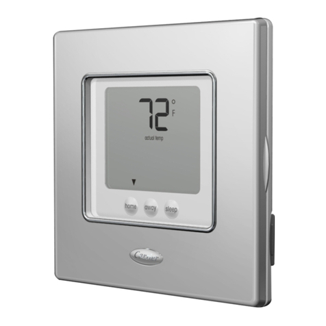
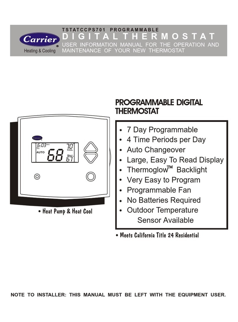
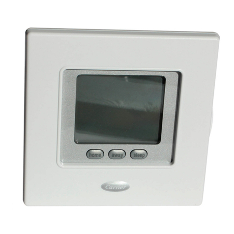
  9. Carrier TSTATCCPS701 User manual

Carrier TSTATCCPS701 User manual

Installation Instructions
TSTATCCPS701
TSTATBBPS701
P374-1100 Digital Thermostat
NOTE R_ _e e_ _ f,_ be_o_eS_" 1,19_e m_
© ©
HEAT
COOL
&
HEAT
PUMP
MULTI-STAGE• SEVENDAYPROGRAMMABLE
Form ¢M-TSTAT-I Z C_n_ets: Pnn_ m US A C,atmlo_t_ 13T_TA38
PREPARATION 2
REMOVE OLD THERMOSTAT 3
WIRE CONNECTIONS 4
WIRING DIAGRAMS 5
CALIBRATION 8
TEST OPERATION 9
TROUBLESHOOTING 10
CAUTION Follow Installation Instructionscarefutty.
DISCONNECT POWER TO THE HEATER -Ak
AIR CONDITIONER BEFOREREMOVING n_, _,
THEOLD THERMOSTATAND INSTALLING
THENEW THERMOSTAT, WARNING
Replacement Components Division _) Carrier Corporation 4/01
This device complies with Part 15 of the FCC rules.
Operation is subject to the following 2 conditions:
(1) This device may not cause harmful interference,
and (2) This device must accept any interference
received, including interference that may cause
undesired operation.
Page I
Proper installation of the thermostat will be
accomplished by following these step
by step instructions. If you are unsure
about any of these steps, call a qualified
technician for assistance.
Assemble tools
\
Flat Blade Wire cutter
Screwdriver & Stripper
Make sure your Heater/Air Conditioner
is working properly before beginning
installation of the thermostat.
Carefully unpack the thermostat.
Save the screws, bracket, and
instructions.
Turn off the power to the Heating/Air
Conditioning system at the main fuse
panel. Most residential systems have
a separate breaker for disconnecting
power to the furnace.
Page 2
Remove the cover of the old thermostat.
If it does not come off easily check for
screws.
Loosen the screws holding the thermostat
base or subbase to the wall, and lift away.
Disconnect the wires from the old
thermostat. Tape the ends of the wires
as you disconnect them, and mark them
with the letter of the terminal for easy
reconnection to the new thermostat.
Keep the old thermostat for reference
purposes, until your new thermostat is
functioning properly.
Page 3
If the terminal designations on your old
thermostat do not match those on the
new thermostat, refer to the chart below,
or the wiring diagrams that follow.
Wire from the
old thermostat
terminal marked
GorF
Y1,YorC
W1,Wor H
Rh, R, M, Mr, A
C
O/B
Y2
W2
RS+5
RS
RS G
CK1
CK2
Function
Fan
Cooling
Heating
Power
Common
Rev. Valve
2nd Stage Cool
2nd Stage Heat
RemoteSensor*5vdc
RemoteSensor Signal
RemoteSensorGrmmd
DryContactSwitch1
DryContact Switch 2
*C may not be used on all systems.
Install on the
new thermostat
connector marked
G
Y1
Wl ,O,B
R
C*
Wl ,O,B**
Y2
W2
RS+5
RS
GND
** O/B is used if your system isa Heat Pump.
Page 4
5 Wire, 1 Stage Cooling, 1 Stage Gas Heat Resldentlal Gas or ElectricHeat*,
0 ElectricCool,splitsystems& package
W2 Y2 RWl Y1 G C units
l l,..=-tat
Im
24 vac common >_
fan relay >_
comoressor relav >_
>-<
Ist staae heat circuit >'<
24 vac return >'_
>-<
*ffusingelectricheat thisoptionmustbe
selected on duringadvancedsetup. >'<
L
E
C
G
Y1
O
R
_(2
N2
4 Wire, 1 Stage Cooling, 1 Stage Gas Heat
O ResidentialGas orEleCtricHeat *,
W2 Y2 R Wl Y1 G C Ek_ctrlcCoo_,spl_systems&package
fan relay
comDressor relay
1st staae heat circuit
24 vac return
*If usingelectricheat this optionmustbe
se/ectedon duringadvancedsetup.
>.<
i>-<
ix
>-<
>..<
>-<
>-<
>._
L
E
C
G
Y1
0
NI
R
(2
PGge5
6 Wire, 2 Stage Cooling, 1 Stage Heat
O
W2 Y2 R W1 YI GCT,...o.tat
ResidenSal 2Stage Cooling, with
Gas c_ Electric Heat"
L
>'K E
24 vac common _ C
fan relay _G
COmlDressor relav _-_ Y1
0
_ J
Ist staoe heat circuit W1
24 vac return R
2nd staqe compressor relay >_' Y2
*If using electric heat, this option must W2
be selected during advanced setup.
6 Wire, 1 Stage Cooling, 2 Stage Heat
O R_id enlJa[& commerdal1 Stage Co_ing,
W2 Y2 R Wl Y1 G Cwith2StageGasorElecUicHeat"
_I Thermostat
24 vac common
fan relay
comDressor relav
1st stage heat circuit
24 vac return
2nd RtRn_ h_Rt _irnHit >-<
L
E
C
G
YI
O
Wl
R
Y2
vV2
Poge 6
7 Wire, 2 Stage Cooling, 2 Stage Heat
O
W2 Y2 RWl Y1 G C
** Commercial heat oumos do not have
the heat pump fumed on in advanced setup
Comrr_rcial Gas or E_ect,c Heat *".
Electric Co_. split systems & package units
includ_g Commerc_l Heat Pumps **
Thermostat
24 vac common
f_n relay
comDressor relay
L
E
C
>-( G
YI
O
I st stage heat circuit ;>_ wl
24 vac retum H
2nd stage compressor relay >'< Y2
2nd mt_ae hP+mt ¢.i_uit
-N2
*** /fusing electrlc heat. _is optlon rnust
be selec_d on during advanced setup+
5Wire, 1 Stage Cooling, 1 Stage Heat - Heat Pump*
O
W2 Y2 R WI Yl G C NoauxJliawheat. msidentialHeatPumps,
splitsystems& packageunits
_(_(_(_ _3 Thermostat
L
E
24 vac common C
mr r I Y1
reversin vlyeypJ.v___ _>_ o
•ff using _1_ heat pump. this option
must be selected on dunng advanced setup.
W1
Y2
W2
Page 7
6Wire, 1 Stage Cooling, 2 Stage Heat, Heat Pump*
O
W2 Y2 R Wl Y1 G C Mo_,tresiden_alsplffandpackage heatpumps
withauxHmwheat
Thermostat
24 vac common
fan relay
comDressor relav
1st staqe heat circuit
24 vac return
>-<
>-<
>-<
>-.<
i>-<
i
ix
?nd ._tn_n_hAnt _ir_==it _-_
*The heat pump option must be selected I
on dutfng advanced setup.
L
E
C
G
YI
0
R
_2
Every thermostat is calibrated before it leaves the factory.
Under normal circumstances there will never be aneed to
recalibrete the thermostat again.
To accommodate special needs, the thermostat may be recalibretad
following these steps:
1. While holding the mode button in, press the fan button for
5 seconds. After all the icons in the display appear, release
the buttons.
2. Press the Up and Down arrow buttons simultaneously, twice.
3. Press the up or down buttons untilthe flashing number
equals the current room temperature.
4. Press the mode button to retum to normal operation.
Page 8
Turn the power on to the Heating/Air
Conditioning system.
Press the MODE button repeatedly until
the HEAT icon appears on the display.
Press the Up or Down buttons until the set
temperature is 10 degrees above room
temperature. The furnace should turn on.
Press the MODE button repeatedly until
the COOL icon appears on the display.
Press the Up or Down buttons until the set
temperature is 10 degrees below room
temperature, The air conditioner should
turn on. NOTE: Most equipment has a
time delay of 5 minutes between cool
cycles. This feature is defeatable on the
thermostat. Consult the Owner's Manual
under Setup, cycles per hour.
Press the MODE button to OFF. Press
the FAN button to Fan On. The fan
should turn on and run continuously.
Page 9
SYMPTOM: When using 4 wires (R, G, W, Y),
the air conditioning equipment tries
repeatedly to turn on, but cannot. At
times the display dims or disappears.
CAUSE: There is not enough power available
to "power share".
REMEDY: Connect a 270 ohm, 10 watt power
resistor at the furnace as shown below.
ForProblem A/C For Problem Heat
o
U
SYMPTOM: The air conditioning does not
attempt to turn on.
CAUSE: The compressor timer lockout may
prevent the air conditioner from
turning on, for a period of time.
REMEDY: Consult the Owner's Manual in
the Setup section to defeat the
cycles per hour and compressor
timeguard.
SYMPTOM: The display is blank.
CAUSE: Lack of proper power.
REMEDY: Make sure power is turned on to
the furnace and 24vat between R& W.
If C is used, 24vac between R & C.
Page 10
SYMPTOM: The air conditioning does not
attempt to turn on.
CAUSE: The cooling setpoint is set too
high.
REMEDY: Consult the Owner's Manual in
the Setup section to lower the
cooling setpoint limit.
SYMPTOM: The heating does not attempt
to turn on.
CAUSE: The heating setpoint is set too
low.
REMEDY: Consult the Owner's Manual in
the Setup section to raise the
heating setpoint limit.
Page II
SYMPTOM: When controlling a residential heat
pump, and asking for cooling, the heat
comes on.
CAUSE: Heat pump is not selected "on" in the
Advanced Setup.
REMEDY: Select heat pump on during Advanced
Setup programming. Consult the Owner's
Manual.
SYMPTOM: When calling for cooling, both
the heat and cool come on.
CAUSE: The Advanced Setup is configured
to control a heat pump, and the hvac
the thermostat is controlling is a
"conventional" (non heat pump)
system.
REMEDY: Consult the Owner's Manual in
the Advanced Setup section to turn
off the heat pump.
P374 1100
C US F(_ _-,,,_,o_,,,,_with FCC Standan_s
USTED _o_ I._o_4E OR OFFICE USE
4Z95
PIN 88-172
Page 12

Other manuals for TSTATCCPS701

1

This manual suits for next models

2

Other Carrier Thermostat manuals

Carrier TSTATCCPF701 User manual

Carrier

Carrier TSTATCCPF701 User manual

Carrier SUI User manual

Carrier

Carrier SUI User manual
Carrier Infinity SYSTXCCWIC01-B User manual

Carrier

Carrier Infinity SYSTXCCWIC01-B User manual

Carrier 33CSCPACHP-01 User manual

Carrier

Carrier 33CSCPACHP-01 User manual

Carrier TSTAT Operation manual

Carrier

Carrier TSTAT Operation manual

Carrier 5+2 DAY PROGRAMMABLEDIGITAL THERMOSTAT User manual

Carrier

Carrier 5+2 DAY PROGRAMMABLEDIGITAL THERMOSTAT User manual

Carrier Cor TP-WEM01-A User manual

Carrier

Carrier Cor TP-WEM01-A User manual

Carrier 33CS Manual

Carrier

Carrier 33CS Manual

Carrier 53DFS250-FS User manual

Carrier

Carrier 53DFS250-FS User manual

Carrier PROGRAMMABLE DIGITAL THERMOSTAT 53DFS250-FS User manual

Carrier

Carrier PROGRAMMABLE DIGITAL THERMOSTAT 53DFS250-FS User manual

Carrier P/N 33CSSN2-MH User manual

Carrier

Carrier P/N 33CSSN2-MH User manual

Carrier Comfort Touch-n-Go User manual

Carrier

Carrier Comfort Touch-n-Go User manual

Carrier P474-1100RF User manual

Carrier

Carrier P474-1100RF User manual

Carrier 50QE900-511WS User manual

Carrier

Carrier 50QE900-511WS User manual

Carrier Cool Share Web-Programmable Thermostat User manual

Carrier

Carrier Cool Share Web-Programmable Thermostat User manual

Carrier Totaline Star P474-1010 User manual

Carrier

Carrier Totaline Star P474-1010 User manual

Carrier 33AW-CS1 User manual

Carrier

Carrier 33AW-CS1 User manual

Carrier Comfort Pro 33CSCNACHP-01 User manual
Carrier

Carrier Comfort Pro 33CSCNACHP-01 User manual

Carrier Debonair 33CS250-RC User manual

Carrier

Carrier Debonair 33CS250-RC User manual

Carrier CONNECT 33CONNECTSTAT User manual

Carrier

Carrier CONNECT 33CONNECTSTAT User manual

Carrier KAAFT0101AAA User manual

Carrier

Carrier KAAFT0101AAA User manual

Carrier Infinity Control Home User manual

Carrier

Carrier Infinity Control Home User manual

Carrier Comfort Non-Programmable User manual

Carrier

Carrier Comfort Non-Programmable User manual

Carrier A07048 User manual

Carrier

Carrier A07048 User manual

Popular Thermostat manuals by other brands

Siemens RDF301.50 Series manual

Siemens

Siemens RDF301.50 Series manual

HaiLin Controls HL8102 Series manual

HaiLin Controls

HaiLin Controls HL8102 Series manual

Bryant LEGACY LINE-RNC T1-PAC installation instructions

Bryant

Bryant LEGACY LINE-RNC T1-PAC installation instructions

Emerson WHITE-RODGERS 1E78 installation instructions

Emerson

Emerson WHITE-RODGERS 1E78 installation instructions

HOTOWELL HTW-61-HT Series quick start guide

HOTOWELL

HOTOWELL HTW-61-HT Series quick start guide

Magnum Heating Sol 300 installation manual

Magnum Heating

Magnum Heating Sol 300 installation manual

Lennox ComfortSense 3000 Series Operation manual

Lennox

Lennox ComfortSense 3000 Series Operation manual

PNM Wi-Fi Web-Programmable Thermostat user manual

PNM

PNM Wi-Fi Web-Programmable Thermostat user manual

prowarm ProTouch IQ V2 user manual

prowarm

prowarm ProTouch IQ V2 user manual

Honeywell Y87RF user manual

Honeywell

Honeywell Y87RF user manual

Secure SCS311 installation instructions

Secure

Secure SCS311 installation instructions

VDH ALFA 29 user manual

VDH

VDH ALFA 29 user manual

Siemens Powers TH 192 S installation instructions

Siemens

Siemens Powers TH 192 S installation instructions

Goodman TSTATG1100-2 owner's manual

Goodman

Goodman TSTATG1100-2 owner's manual

HLS TH 21 operating manual

HLS

HLS TH 21 operating manual

EUROSTER Q7 Installation and operation manual

EUROSTER

EUROSTER Q7 Installation and operation manual

Pfannenberg eliwell ICPlus915s operating instructions

Pfannenberg

Pfannenberg eliwell ICPlus915s operating instructions

THG PARIS G00.5200AE installation instructions

THG PARIS

THG PARIS G00.5200AE installation instructions

manuals.online logo
manuals.online logoBrands
  • About & Mission
  • Contact us
  • Privacy Policy
  • Terms and Conditions

Copyright 2025 Manuals.Online. All Rights Reserved.