manuals.online logo
Brands
  1. Home
  2. •
  3. Brands
  4. •
  5. Carson
  6. •
  7. Projector Accessories
  8. •
  9. Carson CS100 User manual

Carson CS100 User manual

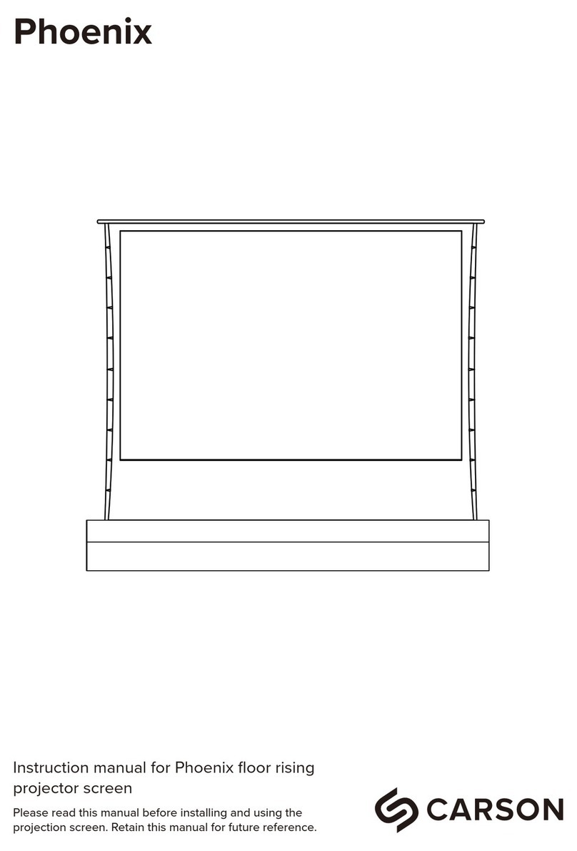
CS100/CS200 Motorized Projector Lift
INSTRUCTION MANUAL FOR
X 1
X 1
(200*M6) X 4
X 1
X 1
X 1
X 1
X1
M4 hexagon allen wrench M6 hexagon allen wrench
X1
X1
RS232/485 cable (1 meter)
X1
12V trigger cable (1 meter)
X1
Parts List
Main body Remote controller
Decorative plate Threaded rod(with 2 nuts)
Patch of mounting plate Measuring plate
Control Box Allen key for motor adjustment
Metal gasket (Ø20*Ø6*1.5)
X 8X 8
Nylon gasket (Ø20*Ø6*6)
Flat-head hexagan socket screw
X 4
Round head hexagon screw
(M6*16)
Power cable
X 4
Expansion screw (M10*60)
Instruction manual
X1
X 1
Flat head cross self-tapping screw
X 2
Round head hexagon socket screw
X 4
(M4*20)
(M5*6)
(M5*40)
X 1
X 8
hanging plate gasket (
Ø30*Ø11.3)
Profile:
It is our latest designe and with strict production control and quality inspection product. It has a good outlook
appearance and easy installation. It is a best choice for professional projectors.
Performance:
1. Ultra thin designed to meet up with narrow installation place.
2. Smooth performance with low noice.
3. Overheat protection function.
4. Easy cabling installation
Specification:
Operating environment for indoor use only:
1. Temperature: -10°C --- +40°C.
2. RH<95%.
3. Environment with non-corrosive gas.
4. Environment without organic aerosol inflammable and explosive gas.
5. Voltage: 100V / 220V (±10%).
6. Avoid violent vibration and collision.
Installation steps :
1. Based on the screen size and the projector’s focal distance to set the installation place,
use the measuring plate to make underline on the false ceiling.
2. Cut out the holes as above underline.
3. Take out the cut board for later using.
4. Mark out 4 locations where the expansion screws should locate on the ceiling by the measuring board.
5. Drilling out those 4 holes as the marks.
6. Screw an expansion screw into each hole.
7. Install the main body onto the screws.
8. With a metal gaskets to each screw, fine adjust the main body to the right position.
9. Drilling out the expansion screws hole onto the real ceiling which beside the lift body(please look out the distance
between the screw hole and the lift motor not exceed its connect cable length), then screw the expansion screw
into the hole, instal the control box by M5 self-tapping screw.
10. Turn the projector lift on and set the UP and DOWN limits.
11. Install the necessary cables such as HDMI.
12. Install the patch of mounting plate by M5 scews.
13. When use M4 screws fixed projector onto the lift tray, please use M6 screws to fixed the decorate plate.
14. When use M4 screws fixed projector hang on the tray, please use M6 screws to fixed the decorate plate, and
fixed the decorte plate to suitable position by adjusting the M6 screw nut.
Body size
(mm)
Model
Spec. Travel distance
(mm)
Lay: projector depth dimention +65
Hang: projector depth dimention +170
Lay: 390*400
Hang: 530*470
20
544*544*168
CM76X 170-750 574*574
Decorative plate
(mm) Load
(kg) Projector size
(mm)
Installation diagram:
Set the DOWN limits
Set the UP limits
Distance from ceilling to
false ceiling(mm)
White adjustment for down limit
Anticlockwise - increase the length of moving down
Clockwise - reduce the length of moving down
Caution: if it’s in the DOWN limit statement, do not turn clockwise
Red adjustment for UP limit
Anticlockwise - increase the lenght of moving up
Clockwise - reduce the length of moving down
Caution: If it’s in the UP limit statement, do not turn clockwise Control System
AC input (110V/220V)
AC output (110V/220V)
12V Trigger
RS232 / RS485
Troubleshooting:
We only recommend experiencedAV installers undertake these procedures:
If the projector lift does not work
1. Restart it after 15 minutes o check if it’s in overheating protection statement or not.
2. Check both terminals of the power cord to see if the problem occurs by the power supply.
3. If the voltage is normal, please check if there’re any loose wires or burned fuse occured.
Warnings:
1. Do not do any adjustment without load weights.
2. Ensure the expansion screws are fixed tightly and properly.
3. To avoid any damages, make sure there’s no any obstructions or people that may impact the product
when operate the projector lift.
4. Ensure the projector is installed in the central point to avoid losing the balance.
5. Never operate the product in overloaded statement.
6. Do not stretch hands or other objects into the lifting arm to avoid any injure or accident.
Precautions for use:
Please refer to below procedures to check if the projector lift is out of order.
1. Make sure the power cord connected properly and be with regular power supply.
2. Do not operate it frequently.
3. Let the motor stop for 15 minutes, then turn it on again to check if the motor is in
an overheating protection statement. If the problem stillremains unsolved, please
contact with us or the dealers for further assistance. Please do not disasssembe or
change the structure by your own.
13 14
Metal gasket
Nylon gasket
Metal gasket
Nylon gasket

This manual suits for next models

1

Other Carson Projector Accessories manuals

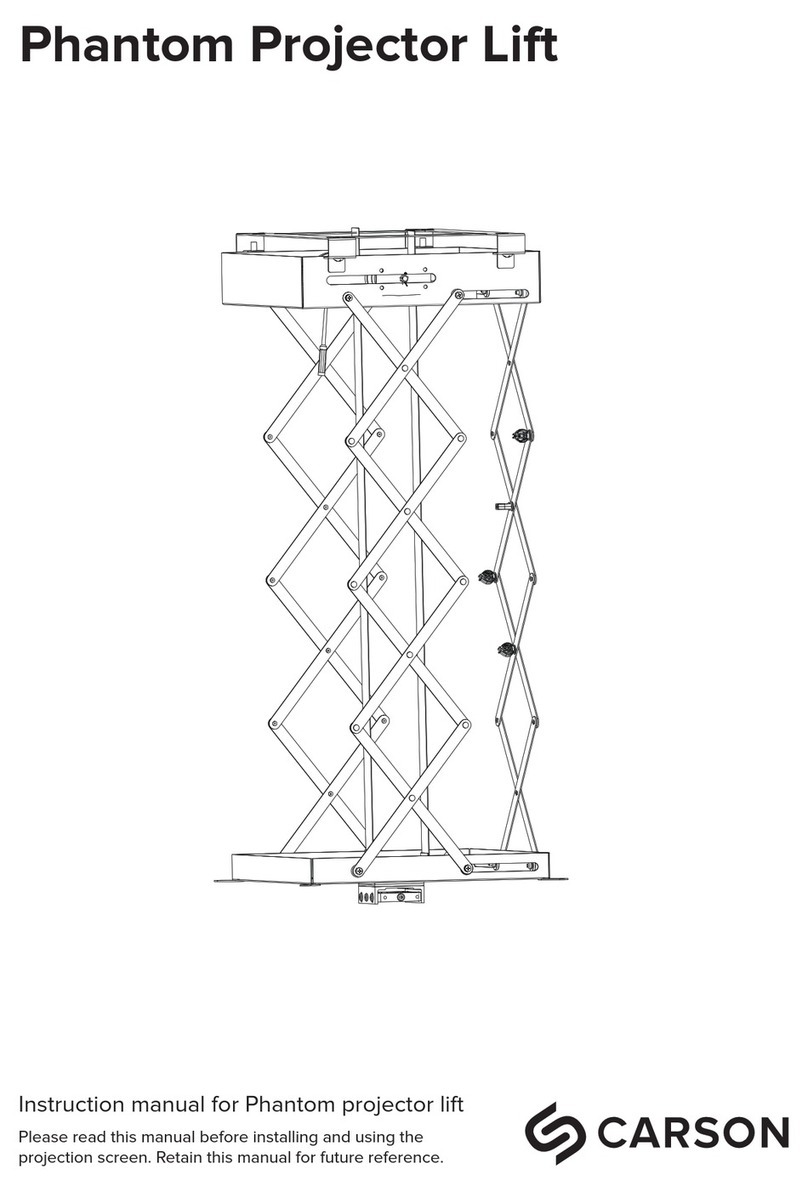
Carson Phantom Projector Lift User manual

Carson

Carson Phantom Projector Lift User manual

Carson Phoenix User manual

Carson

Carson Phoenix User manual

Popular Projector Accessories manuals by other brands

Biamp EasyConnect MPX 200 user guide

Biamp

Biamp EasyConnect MPX 200 user guide

Dynamic Projection MH16 manual

Dynamic Projection

Dynamic Projection MH16 manual

Kramer VIA CONNECT PRO user manual

Kramer

Kramer VIA CONNECT PRO user manual

CHIEF RPE installation instructions

CHIEF

CHIEF RPE installation instructions

VIVID STORM CineVision Pro user manual

VIVID STORM

VIVID STORM CineVision Pro user manual

Extron electronics PCM 240 user guide

Extron electronics

Extron electronics PCM 240 user guide

Barco ClickShare CSE-800 Installation guides

Barco

Barco ClickShare CSE-800 Installation guides

QualGear QG-PRO-PM-PCO-B installation manual

QualGear

QualGear QG-PRO-PM-PCO-B installation manual

Samson AL1 Specification sheet

Samson

Samson AL1 Specification sheet

Remaco PLT-416 installation guide

Remaco

Remaco PLT-416 installation guide

InFocus LP 240 Replacement manual

InFocus

InFocus LP 240 Replacement manual

Digital Projection 117-341 installation guide

Digital Projection

Digital Projection 117-341 installation guide

Maxell FL-720 user manual

Maxell

Maxell FL-720 user manual

iVisions 8719244431786 manual

iVisions

iVisions 8719244431786 manual

Sanyo LNS-S30 Replacement procedure

Sanyo

Sanyo LNS-S30 Replacement procedure

PEERLESS PARAMOUNT I-PPF Installation and assembly

PEERLESS

PEERLESS PARAMOUNT I-PPF Installation and assembly

JT Motors STATIV BASIC MOBIL Series Mounting & operating instructions

JT Motors

JT Motors STATIV BASIC MOBIL Series Mounting & operating instructions

NEC NP03LM Important information

NEC

NEC NP03LM Important information

manuals.online logo
manuals.online logoBrands
  • About & Mission
  • Contact us
  • Privacy Policy
  • Terms and Conditions

Copyright 2025 Manuals.Online. All Rights Reserved.