NEC NP2200 Series Guide

ISSUED:06-16-09 SHEET#:055-XXXX-1
Visit the Peerless Web Site at www.peerlessmounts.com 1 of 9 For customer care call 1-800-729-0307 or 708-865-8870.
Maximum Load Capacity: 50 lb (22.7 kg)
Model: NP3250CM
Features:
• ImageLockTM alignment preventspicturesagordrift
• Wrench access slot for easier flush mount installations
• Exclusive aluminum track quick release
NEC Display Solutions of America, Inc.
Installation and Assembly - Ceiling Mount for NEC
NP1150, NP2150, NP3150, NP3151W, NP1250, NP2250,
NP3250 and NP3250W Projector

ISSUED:06-16-09 SHEET#:055-XXXX-1
Visit the Peerless Web Site at www.peerlessmounts.com 2 of 9 For customer care call 1-800-729-0307 or 708-865-8870.
Table of Contents
Parts List.................................................................................................................................................................... 3
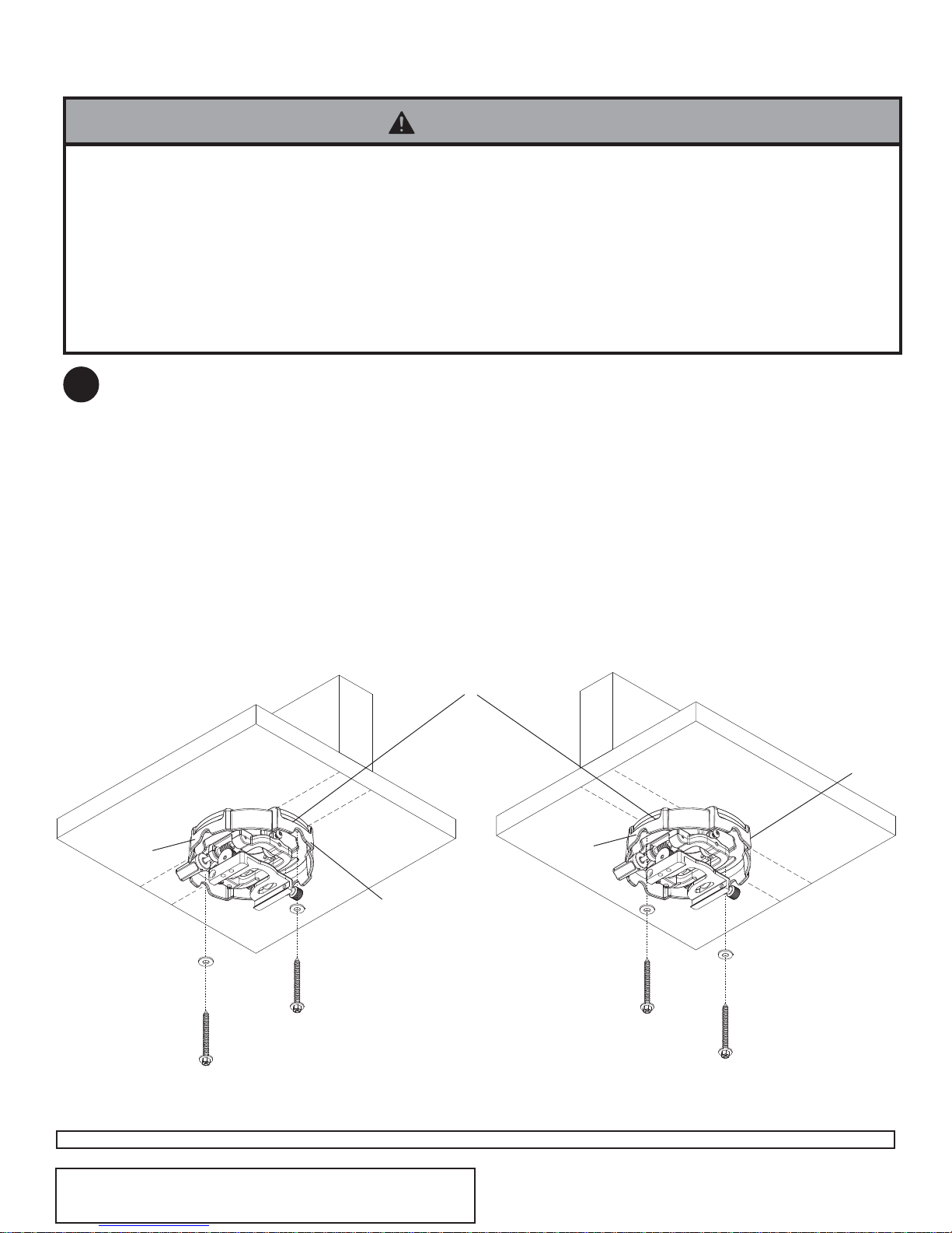
Installation to Wood Joist Ceilings .............................................................................................................................. 4
InstallationtoConcreteCeilings.................................................................................................................................. 5
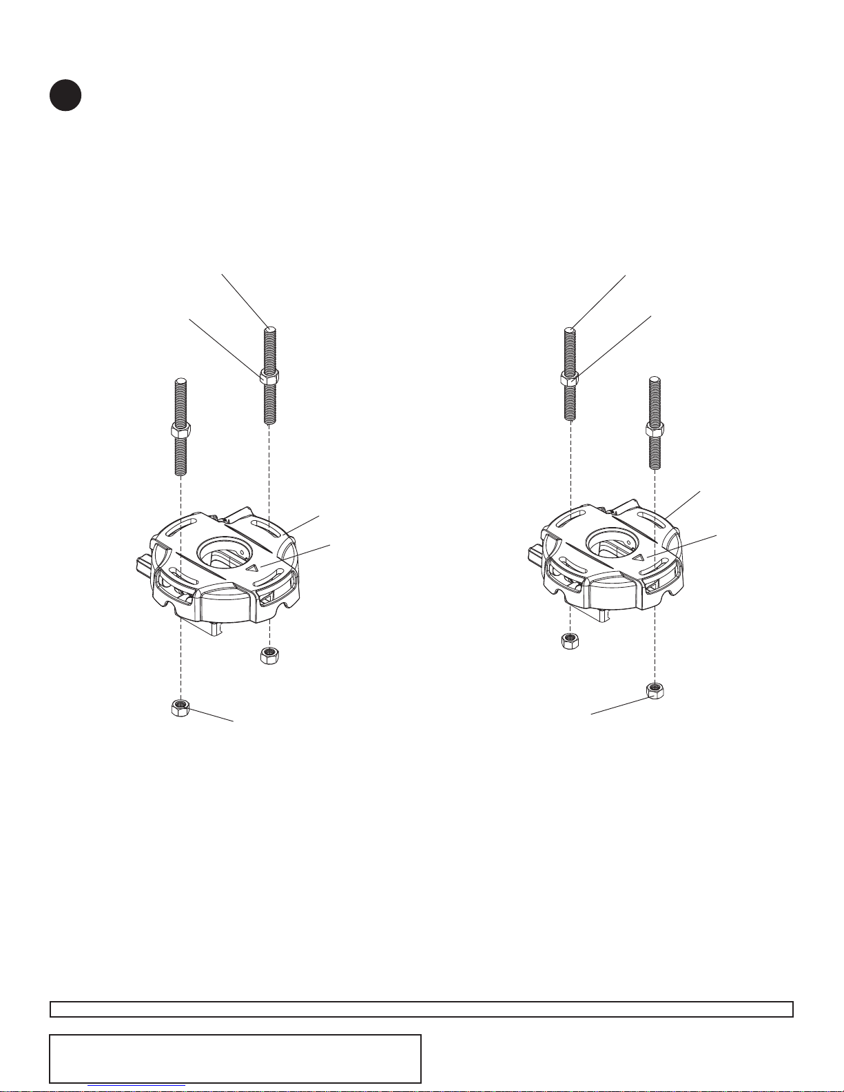
InstallationtoThreadedRods...................................................................................................................................... 6
Installation to Extension Columns / Ceiling Plate........................................................................................................ 7
Attaching Adapter Plate to Projector........................................................................................................................... 8
ProjectorAlignment .................................................................................................................................................... 9
Tools Needed for Assembly
•studfinder ("edge to edge" stud finder is recommended)
•phillipsscrewdriver
•drill
•1/4" bit for concrete surface
•5/32" bit for wood studs
•openendwrench
•level
• It is the responsibility of the installer to ensure that the
projectoris properly ventilated.
CAUTION
NOTE: Read entire instruction sheet before you start installation and assembly.
• Donot begin toinstall your Peerlessproduct until youhave read andunderstood the instructionsand warnings con-
tained in this Installation Sheet. If you have any questions regarding any of the instructions or warnings, call Peerless
customercareat 1-800-729-0307.
• This product should only be installed by someone of good mechanical aptitude, has experience with basic building
construction, and fully understands these instructions.
• Makesure that the supporting surface will safely support the combined load of theequipment and allattached hard-
wareandcomponents.
• Neverexceed theMaximum LoadCapacity.
• Always use an assistant or mechanical lifting equipment to safely lift and position equipment.
• Tighten screwsfirmly, butdo notovertighten. Overtighteningcan damagethe items,greatly reducingtheir holding
power. Seesuggested torquevalues whereapplicable withinthese instructions.
• Thisproduct is intendedfor indoor useonly.Use of thisproduct outdoorscould lead toproduct failure andpersonal
injury.
WARNING

ISSUED:06-16-09 SHEET#:055-XXXX-1
Visit the Peerless Web Site at www.peerlessmounts.com 3 of 9 For customer care call 1-800-729-0307 or 708-865-8870.
Accessories listed in the included sheet, as well as other parts,
can be ordered through Peerless by calling 1-800-729-0307 or
visiting www.peerlessmounts.com.
Note: Actual parts may appear slightly different than illustrated.
Disengageconnection blockfrom projectormount assembly(A) byunscrewing captive screw and sliding out
connection block as shown.
CONNECTIONBLOCK
CAPTIVESCREW
A
BC
A
D
G
E
H
FI
JK
Description Qty. Part #
Aprojector mount assembly 1 055-2803
B4 mm security allen wrench 1 560-9646
C#10-32 x 3/8" serrated washer head socket pin screw 2 520-2151
D#10-32 x 1/4" socket pin screw 1 520-2196
Eflat washer 2 540-1078
F#14 x 2.5 phillips hex head wood screw 2 5S1-015-C04
Gconcrete anchor 2 590-0097
H2 mm security allen wrench 1 560-1097
Iadapter plate 1 055-2665
JM4 x 25 mm serrated socket pin screw 4 510-2082
Kspacer 4 590-2106
Parts List
1

ISSUED: 03-06-06 SHEET #: 055-9452-1
Visit the Peerless Web Site at www.peerlessmounts.com 4 of 9 For customer care call 1-800-729-0307 or 708-865-8870.
Accessories listed in the included sheet, as well as other parts,
can be ordered through Peerless by calling 1-800-729-0307 or
visiting www.peerlessmounts.com.
Place projector mount assembly (A) on ceiling as a template and mark the center of the two mounting holes. Make
sure that the mounting holes are in the center of the wood joist. Drill two 5/32" (4 mm) dia. holes to a minimum
depth of 2.5" (64 mm). Attach projector mount assembly (A) with two #14 x 2.5" (6 mm x 65 mm) wood screws (F)
and two flat washers (E) as shown in figure 2.1 or figure 2.2 depending on joist orientation.
Note:Mountingslotson projector mountassemblyallowfor 30°(±15°)ofswivel adjustment beforefullysecuring
woodscrews.
Tightenwood screws(F)using 3/8"(10 mm)socket wrench, phillips screwdriver or 10mm openend wrenchuntil
projector mount assembly (A) is firmly attached.
Installation To Wood Joist Ceilings
FF
A
WOODJOIST
FRONTOF
MOUNT
EE
WOODJOIST
A
ACCESSSLOTFOR
OPENENDWRENCH
ALLOWSTIGHTENING
OFWOODSCREW
2
• Installermust verify that the supportingsurface willsafely support thecombined loadof the equipment and allattached
hardwareandcomponents.
• Tightenwood screwsso that projectormount assemblyis firmlyattached, but do not overtighten.Overtightening can
damagethe screws,greatly reducingtheir holding power.
• Never tighten in excess of 80 in. • lb (9 N.M.).
• Make sure that mounting screws are anchored into the center of the stud. The use of an "edge to edge" stud finder is
highlyrecommended.
• Hardwareprovided isfor attachmentof mountthrough standard thickness drywall or plaster into wood studs.Installers
areresponsible to providehardware forothertypes ofmounting situations (notUL approved).
WARNING
Skip to step 6.
fig. 2.1 fig. 2.2
ARROWONTOPOF
PROJECTORMOUNT
ASSEMBLYINDICATES
FRONTOFMOUNT

ISSUED:06-16-09 SHEET#:055-XXXX-1
Visit the Peerless Web Site at www.peerlessmounts.com 5 of 9 For customer care call 1-800-729-0307 or 708-865-8870.
Accessories listed in the included sheet, as well as other parts,
can be ordered through Peerless by calling 1-800-729-0307 or
visiting www.peerlessmounts.com.
Drill two 1/4" (6 mm) dia. holes to a minimum depth of
2.5" (64 mm). Attach projector mount assembly (A)
usingtwo concreteanchors (G), two flat washers (E),
and two #14 x 2.5" wood screws (F) as shown in
Illustration A and1,2,and3 (below).Tighten wood
screws (F) using 3/8" (10 mm) socket wrench until
projector mount assembly (A) is firmly attached.
1
3
Drill hole and insert anchor
Place ceiling plate or mount over anchor and secure
with screw
After repeating step one tighten all fasteners
CUTAWAYVIEW
INCORRECT
concrete
metal
bracket
plaster/
drywall
CORRECT
concrete
metal
bracket
plaster/
drywall
concrete
ceiling
F
F
Installation to Concrete Ceilings
2A
G
G
Skip to step 6.
G
• Concrete anchors are notintended for attachment to
concreteceiling coveredwith alayer of plaster,
drywall,or otherfinishing material.If mountingto
concreteceiling coveredwith plaster/drywallis un-
avoidable,plaster/drywall (up to 5/8"thick) must be
counterboredas shownbelow.If plaster/drywallis
thicker than 5/8", custom fasteners must be supplied
by installer.
WARNING
• Tighten woodscrews firmly, butdo notovertighten.
Overtighteningcan damagethescrews, greatly
reducingtheirholding power.
• Never tighten in excess of 80 in • lb (9 N.M.).
WARNING
• Installer must verify that the wall will safely support
fourtimes thecombined weight of all attachedequip-
mentandhardware.
WARNING
F
A
CONCRETECEILING
E
GARROWONTOPOF
PROJECTORMOUNT
ASSEMBLYINDICATES
FRONTOFMOUNT
3

ISSUED: 03-06-06 SHEET #: 055-9452-1
Visit the Peerless Web Site at www.peerlessmounts.com 6 of 9 For customer care call 1-800-729-0307 or 708-865-8870.
Accessories listed in the included sheet, as well as other parts,
can be ordered through Peerless by calling 1-800-729-0307 or
visiting www.peerlessmounts.com.
1/4-20THREADEDROD
(NOTINCLUDED)
Thread two1/4-20 hexthin nylon-insert locknuts (not included)on two1/4-20 threadedrods (notincluded) to the
desired height of projector mount assembly. Attach projector mount assembly (A)to the two 1/4-20 threaded rods
using two 1/4-20 hex thin nylon-insert locknuts as shown in figure 4.1 or figure 4.2.
A
Installation to Threaded Rod
(Not evaluated by UL - Professional installation only)
1/4-20THREADEDROD
(NOTINCLUDED)
A
1/4-20HEXTHIN
NYLON-INSERT
LOCKNUT
(NOTINCLUDED)
4
1/4-20HEXTHIN
NYLON-INSERT
LOCKNUT
(NOTINCLUDED)
1/4-20HEXTHIN
NYLON-INSERT
LOCKNUT
(NOTINCLUDED)
1/4-20HEXTHIN
NYLON-INSERT
LOCKNUT
(NOTINCLUDED)
ARROW
INDICATES
FRONTOF
MOUNT
ARROW
INDICATES
FRONTOF
MOUNT
fig. 4.1 fig. 4.2

ISSUED:06-16-09 SHEET#:055-XXXX-1
Visit the Peerless Web Site at www.peerlessmounts.com 7 of 9 For customer care call 1-800-729-0307 or 708-865-8870.
Accessories listed in the included sheet, as well as other parts,
can be ordered through Peerless by calling 1-800-729-0307 or
visiting www.peerlessmounts.com.
Installation to Extension Column / Ceiling Plate
A
11/2"EXTENSION
COLUMN
(SOLDSEPARATELY)
ULLISTEDEXTORADJ
SERIES)
ARROW
INDICATES
FRONTOF
MOUNT
fig. 5.1
A
3/4"EXTENSIONCOLUMN
(SOLDSEPARATELY)
ACC 913
(NOTULLISTED)
(SOLDSEPARATELY)
fig. 5.2
fig. 5.3
5
SWIVELSTOP
SCREW
CMJ455
(SOLDSEPARATELY)
ARROW
INDICATES
FRONTOF
MOUNT
NOTE: Referto accompanying instructions with ceiling plates (soldseparately) for installingthese models to
ceiling.
Screw projector mount assembly (A) onto extension column as shown in figure 5.1.
NOTE: For 3/4" extension columns, reducer ACC 913 will be required as shown in figure 5.2. Tighten swivel stop
screw against extension column, flush mount tube or reducer using 4 mm security allen wrench (B) as shown in
figure 5.3.
NOTE: Swivel stop screw is used to jam against threads of extension column, flush mount tube or reducer to
preventanyexcessmovementofprojectormountassembly(A).Donotovertightenscrew;overtighteningscrewwill
damagethreads makingit difficult to separate products.
Skip to step 6.

ISSUED: 03-06-06 SHEET #: 055-9452-1
Visit the Peerless Web Site at www.peerlessmounts.com 8 of 9 For customer care call 1-800-729-0307 or 708-865-8870.
Accessories listed in the included sheet, as well as other parts,
can be ordered through Peerless by calling 1-800-729-0307 or
visiting www.peerlessmounts.com.
Note:Theprojector you are installingmay differinappearance fromthe sampleillustrated below.
Align shoulder on connection block opposite notch in adapter plate. Attach adapter plate (I) to connection block
from projector mount assembly (A) using two #10-32 x 3/8" serrated washer head socket pin screws (C) as shown.
CONNECTIONBLOCK
C
NOTCHINDICATES
FRONTOFPROJECTOR
SHOULDER
*Notch indicates front of projector.
Flip projector upside down. Fasten adapter plate (I)by using four spacers (K) and four M4 x 25 mm serrated socket pin
screws (J) as shown below. Tighten M4 x 25 mm serrated socket pin screws (J) using 4 mm allen wrench (B).
I
J
Spacers (K) go
between adapter plate
and projector.
I
6
7

ISSUED:06-16-09 SHEET#:055-XXXX-1
Visit the Peerless Web Site at www.peerlessmounts.com 9 of 9 For customer care call 1-800-729-0307 or 708-865-8870.
Accessories listed in the included sheet, as well as other parts,
can be ordered through Peerless by calling 1-800-729-0307 or
visiting www.peerlessmounts.com.
Slideconnection block with projectorinto projector mount
assembly (A) as shown. Tighten captive screw to secure
projectorto projectormount assembly (A).
IMPORTANT: For security installations, insert
one #10-32 x 1/4" socket pin screw (D) through
projectormount assembly(A) and into connection
block as shown.
ACONNECTIONBLOCK
D
CONNECTIONBLOCK
A
CAPTIVESCREW
FRONTOFMOUNT
• Always use an assistant or mechanical lifting equipment to safely lift and position the projector mount.
WARNING
©2006PeerlessIndustries,Inc.Allrightsreserved.
PeerlessisaregisteredtrademarkofPeerlessIndustries.
Allotherbrandandproductnamesaretrademarksorregisteredtrademarksoftheirrespectiveowners.
To adjust yaw (swivel) for threaded rod mounting applications:Loosen locknuts on threaded rods
(step 5), until projector mount can be rotated. Rotate mount to desired position and retighten locknuts.
To adjust yaw (swivel) for extension column applications: Loosen screw on projector mount assembly (A)
indicated below until projector mount can be rotated. Rotate mount to desired position and retighten screw.
To adjust pitch (forward and backward tilt): Turn knob on back of mount as shown below. Pull knob out and
turn by hand for easy adjustment or insert #2 phillips screwdriver in end of knob and turn.
To adjust roll (side to side tilt): Turn knob on side of mount as shown below. Pull knob out and turn by hand
foreasy adjustment orinsert #2 phillips screwdriver inend of knob and turn.
Projector Alignment
SCREWFORYAW(SWIVEL)STOP
(REFERTOSTEP2,INSTALLATION
TOEXTENSIONCOLUMNS,FIG.2.3)
A
KNOBFORROLL
ADJUSTMENT
KNOBFORPITCH
ADJUSTMENT
BACKOFMOUNT
10
ACCESSSLOTFOR
OPENENDWRENCH
ALLOWSTIGHTENING
OFLOCKNUTS
WITHOUTREMOVING
PROJECTOR
ARROWINDICATES
FRONTOFMOUNT
8 9
Other manuals for NP2200 Series
3
This manual suits for next models
10
Table of contents
Other NEC Projector Accessories manuals
Popular Projector Accessories manuals by other brands

HuddleCamHD
HuddleCamHD HuddleShare user manual

IOGear
IOGear Duplicast Wireless Screen Mirroring Kit quick start guide

Navitar
Navitar 631MCL1028 installation instructions

Da-Lite
Da-Lite Dual Masking Electrol Instruction book

Vivo
Vivo PS-M-100 instruction manual

Huawei
Huawei TP1102 Series Administrator's guide