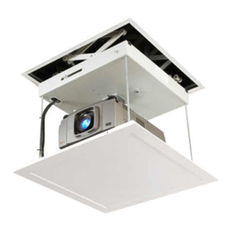
Draper AeroLift 35 User manual

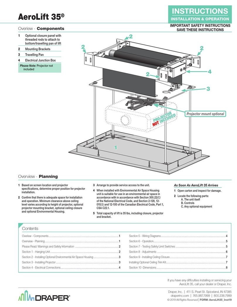
AeroLift 35
Environmental Air Space Housings, Closures & Ceiling Trim Kits
If you encounter any difficulties installing your AeroLift 35 Environmental
Air Space Housing, Closure or Ceiling Trim Kit, call your dealer or Draper,
Inc. in Spiceland, Indiana, 765-987-7999 or fax 765-987-7142.
Copyright ©2016 Draper, Inc. Form AeroLift35-Options_Inst16 Printed in U.S.A.
Installing Optional Environmental Air Space Housing
The Environmental Air Space Housing is shipped pre-assembled in its shortest
position. The height of the housing can be adjusted by moving the screws to differ-
ent mounting holes in side panels. The incremental adjustment for the top screw
and bottom screw is ½"; the incremental adjustment for the rest of the screws is 1".
You can install the housing in a pre-assembled state or as separate components,
which will require that the housing be completely disassembled prior to installation.
Please note that if the Environmental Air Space Housing is to be installed in a
space where there is no access from above the housing, then it is recommended
that the AeroLift 35 be installed to the upper section prior to installing the housing.
It is also recommended that an access panel be installed to allow future access.
1Install top section of housing using outer
four holes located on top of upper section.
If installing large housing, make sure it is
oriented properly to allow correct
placement of lift within housing.
2If installing the large closure, attach
brackets to bottom of projector plate.
3Attach AeroLift 35 to upper section of
housing through the inner four holes
in the upper section with the
5
/
16
" –18 x
7
/
8
"
hex head screws,
5
/
16
" flat washers and
lock nuts provided with housing. The lock
nuts should be used above the housing
(one per screw).
4Attach the two flat panels of the middle
section across from each other with the
clinch nuts to the outside of the housing.
5Attach the two middle section panels with
the formed ends across from one another.
6Attach lower section of Environmental
Air Space Housing.
A - Upper Section
B - Middle Section
(Inside View)
C - Lower Section
(Ceiling Trim Kit)
Environmental Air Space
Housing (small, collapsed)
Large Environmental Air Space Housing
and Closure Dimensions
Closure Panel 25"
EASH Mounting Holes 20
5/8"
Ceiling Trim Ring 23 7/8"
Ceiling Trim Ring 23 7/8"
Lipless Closure Dims: 22 1/8" x 22 1/8"
Closure
Panel
25"
Top View
Closure Panel 25"
22 5/8"
EASH 23 ½"
Between Rod
20 11/16"
Center of Rod
21"
22 5/8"
EASH 23 ½"
Ceiling Trim Ring 23 7/8"
12 5/8"
to
20 5/8"
EASH
EASH
Between Rod
20 11/16"
Center of Rod
21"
Trim
Ring
Closure
Panel
Closure Panel 25"
Ceiling Trim Ring 23 7/8"
Side ViewFront/Back View
Ø 3/8" 8x
19 3/8"
10 1/8"
Lift
Mounting
Holes
EASH Mounting Holes 20 5/8"
Top View
Closure
Panel
15 5/8"
Ceiling Trim Ring 14
9
/
16
"
Ceiling Trim Ring 23 7/8"
EASH Mounting Holes 21¼"
Lift
Mounting
Holes
Ø 7/16" 4x
Closure Panel 25"
Closure Panel
15 5/8"
EASH 14 ¼"
Ceiling Trim Ring
14 9/16"
13 3/16"
12 5/8"
to
20 5/8"
Closure Panel 25"
Between
Rod
9
9
/
16
”
Center
of Rod
10
1
/
8
”
Between Rod
20 11/16"
Center of Rod
21"
22 5/8"
EASH 23 ½"
Ceiling Trim Ring 23 7/8"
EASH
EASH
Trim
Ring
Closure
Panel
Front/Back ViewSide View
Lipless Closure Dims: 22 1/8" x 12 1/8"
19 3/8"
10
1
/
8
”
EASH Mounting
Holes 8¾"
Small Environmental Air Space Housing
and Closure Dimensions
Video Conferencing Camera Shelf (AeroLift 35 Only)
1”
119/16”
11/16”
6¾”
to
11¾”
Closure Panel 137/8”
7½”
Trim Ring 13
9
/
16
”
12
7
/
16
”
93/8”
to
143/8”
Space Between
9¾”
10”
11”
12¼”
19/16”
149/16”
Closure Panel 167/8”
Trim Ring 16 9/16”
15 7/16”
213/16”
20 3/16”
EASH 14 ¼"
EASH
CLOSURE PANEL
TRIM RINGTRIM RING
EASH
EASH 23 ½"
Top View
Closure
Panel
15 5/8"
Ceiling Trim Ring
14 9/16"
Ceiling Trim Ring 23 7/8"
EASH Mounting Holes 21¼"
Lift
Mounting
Holes
Ø 7/16" 4x
Closure Panel 25"
Closure Panel
15 5/8"
EASH 14 ¼"
Ceiling Trim Ring
14 9/16"
13 3/16"
12 5/8"
to
20 5/8"
Closure Panel 25"
Between
Rod
9
9/16”
Center
of Rod
101/8”
Between Rod
20 11/16"
Center of Rod
21"
22 5/8"
EASH 23 ½"
Ceiling Trim Ring 23 7/8"
EASH
EASH
Trim
Ring
Closure
Panel
Front/Back ViewSide View
Lipless Closure Dims: 22 1/8" x 12 1/8"
19 3/8"
10
1
/
8
”
EASH Mounting
Holes 8¾"
Closure Panel 25"
EASH Mounting Holes 20 5/8"
Ceiling Trim Ring 23 7/8"
Ceiling Trim Ring 23 7/8"
Lipless Closure Dims: 22 1/8" x 22 1/8"
Closure
Panel
25"
Top View
Closure Panel 25"
22 5/8"
EASH 23 ½"
Between Rod
20 11/16"
Center of Rod
21"
22 5/8"
EASH 23 ½"
Ceiling Trim Ring 23 7/8"
12 5/8"
to
20 5/8"
EASH
EASH
Between Rod
20 11/16"
Center of Rod
21"
Trim
Ring
Closure
Panel
Closure Panel 25"
Ceiling Trim Ring 23 7/8"
Side ViewFront/Back View
Ø 3/8" 8x
19 3/8"
10 1/8"
Lift
Mounting
Holes
EASH Mounting Holes 20 5/8"

Installing Optional Ceiling Trim Kit
The AeroLift 35 is available with a ceiling trim kit, which consists of the lower
section of the Environmental Air Space housing and optional closure panel.
1Install AeroLift 35 as previously
described in these instructions.
2Install bottom section of housing in
opening. This can be accomplished
by suspending with wire, or by
mounting directly to the ceiling
joists (if space permits).
3Install projector and attach
optional ceiling closure to
AeroLift 35.
Ceiling tile
(by others)
Lower section of
Environmental Air
Space Housing
Trim Ring
1/8" Min. clearance
Caution: Make
sure there are
no obstructions
to the AeroLift's
operation
AeroLift Clearance
www
.draperinc.com (765) 987-7999
The optional ceiling closure can be used as is, or in conjunction with, a square of existing ceiling tile.
1If installing with ceiling tile, you may need to cut tile so that its overall dimensions are the same as
(or slightly less than) the closure panel. Place tile into trim frame. Lay closure panel on top (back side)
of ceiling tile, and tighten screws to hold in place.
Lipless Closure Option is available by removing the Trim Ring from the Closure Panel.
A substrate material (ceiling tile, gypsum board, etc.) can be attached directly to the
Closure Panel using adhesive, double-sided tape or screws. NOTE: Make sure the added
weight of the substrate does not exceed the stated weight capacity of the lift.
Substrate should be installed so that it is centered within the finished opening in the
ceiling, with a gap of no less that
3
/
16
" around all edges.
Lipless Closure dimensions shown with *in drawing on page 1.
2Attach provided angle brackets to side of Bottom Panel of AeroLift.
3Attach threaded rods to angle bracket.
4Run unit “up” until bottom pan stops at highest position. Mark position on
5
/
16
" rods even
with ceiling level and cut to length (remove from pan if convenient).
5Run unit “down” until bottom pan stops at “show” position.
6Attach closure to lower end of rods by slipping into four corner slots.
Secure with nuts above and below slots.
Caution: Make sure nuts are completely tightened.
7Run unit “up” again to highest position. Measure distance by which panel
fails to reach required “closed” height for surrounding ceiling.
8Run unit “down” then re-adjust mounting of rods in traveling grid to raise panel required distance.
9Test unit operation to confirm that panel will stop in closed position just before touching ceiling.
Caution: DO NOT hang from, "ride" or pull down on the unit.
This could create a failure and cause damage and/or injury.
PLEASE NOTE: Immediately upon completion of the surrounding ceiling, unit
should be operated to confirm that optional ceiling closure panel by Draper or
by others stops
1
/
8
" short of touching ceiling in closed position. If closure
panel touches, the motor may continue operating after the lift is closed.
If it continues to cycle once the lift is closed, a motor failure may occur.
ISO VIEW
(REFERENCE ONLY)
Video Conferencing Camera
Closure (AeroLift 35 Only)
See Installation Instructions
included with Video Conferencing
Camera Closure.
AeroLift 35 Closure Installation
Installing Projector Using Universal Projector Mount
Draper’s optional Universal Projector
Mount will hold up to 26 lbs.
See Installation Instructions
included with Universal Pojector Mount.
7"
(178mm)
2½"
(64mm
)
10" (254mm)
12" (305mm)
12" (305mm)
5½"
(140mm)
7"
(178mm)
2½"
(64mm)
10" (254mm)
12" (305mm)
12" (305mm)
5½"
(140mm)
AeroLift 35 Environmental Air Space Housings, Closures & Ceiling Trim Kits Page 2 of 2
For Additional Safety:
1Be sure the nuts that attach the threaded
rods to the closure panel are tight.
2Wrap a plastic wire tie around the mounting
tab and the threaded rod at all four corners
of the closure panel (Fig 9).
Please Note: Do NOT use a
paper-covered or similar wire tie—
use only plastic wire ties for
maximum safety.
1 300319 - 300320 AeroLift 35 UL
4 C020.153 Screw ¼” - 20 x ¾” Grade 2 Zinc HexHd Cap
Item
Q
ty Part Number Description
1044.225.08SA Panel, AL35 / MPL Closure
16 C018.028 Nut 5/16"-18 Zinc Hex
4 C077.052 Rod, Threaded 5/16” - 18 x 16” L Zinc
8 C020.082 Screw, #10-16 X x ½” L. 6 Lobe Torx Hd White
16 C013.050
Washer .375 I.D.x .875" O.D. x .064”TK GRD Zinc Flat
1 C028.183.08SA Frame, Closure Trim
2 C002.1226.01SA Bracket, AL35 Side Closure
2 C002.1227.01SA Bracket, AL35 Front/Back Closure
16 C013.033
Washer, ¼” Wide 5/16” ID x 47/64” OD x 1/16” Thk Zinc Flat
8 C018.014 Nut, .250-20 Nylon InsertedHex Zinc Locking
4 C020.130 Screw ¼” - 20 x 1” Hex Hd GR 2 Zinc Cap
C
D
E
F
H
I
J
KM
N
H
J
I
K
Threaded
Rod
AeroLift 35
Closure
Trim Frame
G
Closure
Bracket
Closure Panel
B
1 300319 - 300320 AeroLift 35 UL
4 C020.153 Screw ¼” - 20 x ¾” Grade 2 Zinc HexHd Cap
Item
Q
ty Part Number Description
1044.225.08SA Panel, AL35 / MPL Closure
16 C018.028 Nut 5/16"-18 Zinc Hex
4 C077.052 Rod, Threaded 5/16” - 18 x 16” L Zinc
8 C020.082 Screw, #10-16 X x ½” L. 6 Lobe Torx Hd White
16 C013.050
Washer .375 I.D. x .875" O.D. x .064”TK GRD Zinc Flat
1 C028.183.08SA Frame, Closure Trim
2 C002.1226.01SA Bracket, AL35 Side Closure
2 C002.1227.01SA Bracket, AL35 Front/Back Closure
16 C013.033
Washer, ¼” Wide 5/16” ID x 47/64” OD x 1/16” Thk Zinc Flat
8 C018.014 Nut, .250-20 Nylon InsertedHex Zinc Locking
4 C020.130 Screw ¼” - 20 x 1” Hex Hd GR 2 Zinc Cap
C
D
E
F
H
I
J
KM
N
H
J
I
K
Threaded
Rod
AeroLift 35
Closure
Trim Frame
G
Closure
Bracket
Closure Panel
B
Other Draper Projector Accessories manuals
Draper
Draper 220V Silhouette V Guide
Draper
Draper nocturne+ c User manual
Draper
Draper Silhouette/V Guide

Draper
Draper Scissor Lift SL User manual

Draper
Draper AeroLift 50 User manual
Draper
Draper Micro Projector Lift Programming manual
Draper
Draper AeroLift 150 User manual
Draper
Draper AeroLift 35 Programming manual

Draper
Draper AeroLift 35 Manual

Draper
Draper AeroLift 150 User manual
Draper
Draper SL4 Manual
Draper
Draper Large Targa User manual
Draper
Draper ShadowBox Clarion User manual
Draper
Draper 300213 User manual

Draper
Draper AeroLift 150 Manual

Draper
Draper Micro Projector Lift User manual

Draper
Draper AeroLift 35 User manual
Draper
Draper Acumen E Installation instructions

Draper
Draper AeroLift 35 User manual
