Cartechno NA-VL2MBN45 User manual

Version 18.11.2015
Video-inserter
NA-VL2MBN45
Video-inserter with 2 video + RGB + rear-view camera input and CAN control
Product features
Video-inserter for factory -infotainment monitors
2 CVBS video-inputs for after -market devices (e.g. DVD-Player, DVB -T tuner, …)
Built-in audio-switch for (no audio-insertion)
Rear-view camera CVBS video-input
Automatic switching to rear-view camera input on engagement of reverse gear
Activatable parking guide lines for rear-view camera (not all vehicles)
RGB-input for after -market navigation
Video-in-motion (ONLY for connected video-sources)
Compatible with factory rear-view camera
AV-inputs PAL/NTSC compatible
for Mercedes Benz vehicles
generation NTG4.5-204 with
Comand Online, Audio50 APS or Audio 20
with 4pin HSD LVDS connector on the monitor

Version 18.11.2015
Page
2
Contents
1. Prior to installation
1.1. Delivery contents
1.2. Checking the compability of vehicle and accessories
1.3. Boxes and connectors
1.3.1. Video-interface
1.3.2. CAN-bus box
1.4. Dip-switch sengs
1.4.1. Enabling the interface’s video inputs (dip 1-3)
1.4.2. RGB-video input signal selecon for aer-market navigaon (Dip 4)
1.4.3. Rear-view camera seng (dip 5)
1.4.4. Monitor selecon (dip 7-8)
2.Installation
2.1. Place of installaon
2.2. Connecon schema
2.3. Connecng video-interface and CAN-box
2.4. Connecon to the factory monitor
2.5. Connecon to the head-unit
2.6. Connecng peripheral devices
2.6.1. Aer-market RGB navigaon
2.6.2. Video-sources to AV1 and AV2
2.6.3. Audio-switch and audio-insertion
2.6.3.1. Audio inseron by factory audio AUX - NO factory media-interface in vehicle
2.6.3.2. Audio inseron by factory audio AUX – vehicles with factory media-interface
2.6.4. Aer-market rear-view camera
2.6.4.1. Case 1: CAN-box detects reverse gear
2.6.4.2. Case 2: CAN-box does not detect reverse gear
2.6.4.3. Video signal connecon
2.7. Connecng video-interface and keypad
2.8. Picture sengs and guide lines
3. Interface operation
3.1. By Comand-buons
3.2. By keypad
4. Specications
5. Frequently asked questions
6. Technical support

Version 18.11.2015
Page
3
Legal Information
By law, watching moving pictures while driving is prohibited, the driver must not be
distracted. We do not accept any liability for material damage or personal injury resulng,
directly or indirectly, from installaon or operaon of this product. This product should only
be used while standing or to display fixed menus or rear-view-camera video when the
vehicle is moving, for example the MP3 menu for DVD upgrades.
Changes/updates of the vehicle’s soware can cause malfuncons of the interface. If
available, we offer free soware-updates for our interfaces for one year aer purchase. To
receive a free update, the interface must be sent in at own cost. Labor cost for and other
expenses involved with the soware-updates will not be refunded.
1. Prior to installation
Read the manual prior to installaon.
Technical knowledge is necessary for installaon. The place of installaon must be free of
moisture and away from heat sources.
1.1. Delivery contents
Take down the serial numberof the interface and store this manual for support
purposes: ____________________

Version 18.11.2015
Page
4
Requirements
Vehicle Vehicles generaon NTG4.5
Head-unit/monitor Comand Online NTG4.5, Audio20 NTG4.5
with 4pin HSD LVDS connector on the monitor
Limitations
Video only The interface inserts ONLY video signals into the infotainment.
For audio inseron a factory audio-AUX input or FM-modulator
is required. For AUX opon coding we offer OBD-N45-X-01.
Factory media interface If available, its AUX cable with 3.5mm jack (available at MB), can
be used for audio inseron. While used for audio inseron, the
Apple adapter or USB adapter cannot be used simultaneously.
Factory rear-view camera Automac switch-back from inserted video to factory rear-view
camera only while reverse gear is engaged. To delay the switch-
back me, addional electronics is required.
1.2. Checking the compatibility of vehicle and accessories
1.3. Boxes and connectors
1.3.1. Video-interface
The video-interface converts the connected aer-market sources video signals to an LVDS
signal which is the inserted into the factory monitor on certain trigger opons.

Version 18.11.2015
Page
5
1.3.2. CAN-bus box
The CAN-bus box reads digital signals from the CAN-bus and converts them for the video-
interface.
1.4. Dip-switch settings
Some sengs must be selected by the dip-switches on the
video-interface. Dip posion down is ON and posion up is OFF.
See following chapters for detailed informaon.
1.4.1. Enabling the interface’s video inputs (dip 1-3)
Only the enabled video inputs can be accessed when switching through the interface’s video
sources. It is recommended to enable only the required inputs for the disabled will be
skipped when switching through the video-interfaces inputs.
1.4.2. RGB-video input signal selection for after -market navigation (Dip 4)
If an aer-market RGB navigaon or other RGB video source is connected, the source’s RGB
output signal must match the interface’s RGB video input seng.
Note: Seng 800x600 is only possible on Comand HU with 7” monitor.
Dip
Function
ON (down)
OFF (up)
1
RGB-input
enabled
disabled
2
CVBS AV1-input
enabled
disabled
3
CVBS AV2-input
enabled
disabled
4
RGB-input resoluon
800x600
400x240 or 480x240
5
Rear-view cam type
aer-market
factory or none
6
No funcon
-
set OFF
7
Monitor
selecon
Try all 4 possible combinaons of dip 7 and 8 to find the
best picture (quality and size)
8

Version 18.11.2015
Page
6
1.4.3. Rear-view camera setting (dip 5)
If set to OFF, the interface switches to factory LVDS picture while the reverse gear is engaged
to display factory rear-view camera or factory opcal park system picture.
If set to ON, the interface witches to its rear-view camera input CAM while the reverse gear
is engaged.
1.4.4. Monitor selection (dip 7-8)
Dip 7 and 8 are for monitor-specific video sengs which cannot be predicted as even within
the same head-unit version, the monitor specificaons may vary. It is necessary to try all
possible combinaons (both OFF, both ON, 7 OFF and 8 ON, 7 ON and 8 OFF) - while a
working video source is connected to the chosen input of the interface - to see which
combinaon gives the best picture quality and size (some may give no picture). It is possible
to first hot plug through the dip combinaons, but if you do not experience any change of
picture aer trying all 4 opons, retry and disconnected the 6pin power plug of the video-
box between every change of the dip seng.
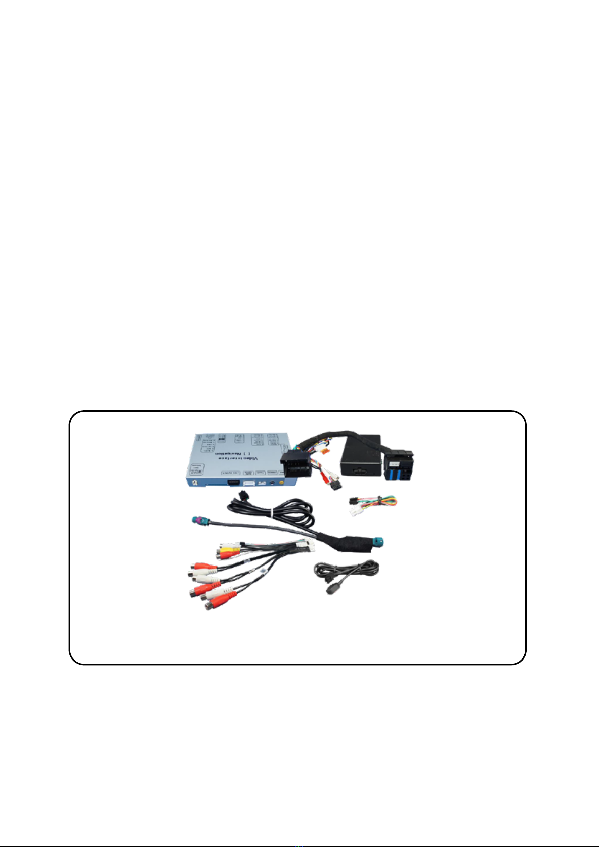
2. Installation
Switch o ignition and disconnect the vehicle’s battery! The interface needs a permanent
12V source. If according to factory rules disconnecting the battery is to be avoided, it is
usually sucient to put the vehicle is sleep-mode. In case the sleep-mode does not show
success, disconnect the battery with a resistor lead.
If power source is not taken directly from the battery, the connection has to be checked
for being start-up proven and permanent.
2.1. Place of installation
The interface is installed on the backside of the factory monitor and on the backside of the
head-unit.

Version 18.11.2015
Page
7
2.2. Connectionschema

Version 18.11.2015
Page
8
Connectingvideo-interface and CAN-box
The CAN-bus box reads digital signals from the CAN-bus and converts them for the video-
interface. ACC +12V max. 0.5A (red of 6pin) and reverse gear +12V max. 0.5A (green of 6pin)
constant signal. Video-source switching (white of 6pin) as +12V impulse. Addionally there is
adata exchange, e.g. for steering wheel posion for driving path lines (grey of 6pin).
Connect black female 10pin Microfit connector of the Quadlock harness to the male
10pin Microfit connector of the CAN-box.
Note: Check LEDs on CAN-box aer reconnecng the baery, two must be on.
Connect white female 6pin Molex connector of the 6pin to 8pin cable to the male
6pin Molex connector of the video-interface.
Connect black female 8pin Microfit connector of the 6pin to 8pin cable to male 8pin
Microfit connector of the CAN-box.
Note: Check LEDs on video-interface aer reconnecng the baery, one must be on.
Note: The CAN-box is not compable with all vehicles. If the CAN-box does not deliver ACC
to pin2 of the video-interface or blocks the vehicle CAN, it is possible to install without CAN-
box. In this case see also note in chapter aer-market rear-view camera if one is supposed to
be connected.

Version 18.11.2015
Page
9
2.3. Connections to the factory monitor
Remove factory monitor.
Connect female 8pin Microfit connector of the 4pin HSD LVDS cable to male 8pin
Microfit connector of the video-interface.
Remove female 4pin HSD LVDS connector from the rear of the factory monitor and
connect it to the male 4pin HSD LVDS connector of the 4pin HSD LVDS cable.
Connect female 4pin connector of the 4pin HSD LVDS cable to the male 4pin HSD
LVDS connector of the factory monitor.

Version 18.11.2015
Page
10
2.4. Connections to the head-unit
Remove head-unit.
Remove the female Quadlock connector of the vehicle harness from the rear of the
navigaon computer.
Remove opcal leads –if exisng- from the female Quadlock connector of the vehicle
harness and insert them into the female Quadlock connector of Quadlock harness at
the same posion.
Connect female Quadlock connector of vehicle harness to the male Quadlock
connector of Quadlock harness.
Connect female Quadlock connector of Quadlock harness to the male Quadlock
connector of the head-unit.
2.5. Connecting peripheral devices
It is possible to connect an aer-market RGB navigaon (or other RGB video source), 2 aer-
market AV-sources and an aer-market rear-view camera to the video-interface.
Before nal installation of the per ipheral devices, we recommend a test-run of the
interface. Due to changes inthe production of the vehicle manufacturer is always the
possibility of incompatibility.

Version 18.11.2015
Page
11
2.5.1. After-Market RGB navigation
Connect female 8pin connector of the RGB cable to the male 8pin connector of the
video-interface. The loose grey wires have no funcon and have to be isolated.
Connect male 6pin connector of the RGB cable to the aer-Market navigaon.

Version 18.11.2015
Page
12
2.5.2. Video-sources to AV1 and AV2
Connect female 6pin connector of the video cable to male 6pin connector of the
video-interface.
Connect video RCA of the AV-source 1 to the female RCA connector Video 1 of the
video cable.
Connect video RCA of the AV-source 2 to the female RCA connector Video 2 of the
video cable.

Version 18.11.2015
Page
13
2.5.3. Audio-switch and audio insertion
This interface can only insert video signals into the factory infotainment and switch audio
signals. If an AV-source is connected to AV1 or AV2, audio inseron must be done by factory
audio AUX input or FM-modulator to which the interface’s sound-switch output is
connected. When the interface is switched from AV1 to AV2, the audio signal is switched
parallel to the corresponding video signal by the interface’s built-in audio-switch.
The inserted video-signal can be acvated simoultaneously to each audio-mode of the
factory infotainment.
Depending whether the vehicle is equipped with a factory media interface, the factory AUX
connecons for audio inseron needs to be done in different ways which are described in
the sub chapters.
Audio pins
Denition
½
Audio input signal R/L of source AV2
¾
Audio input signal R/L of source AV1
5/6
Audio output signal R/L of factory audio AUX
or FM-modulator
7
Ground
Note: If only one AV-source shall be connected, it is possible to connect the video output of
the AV-source to the video input AV1 of the video-interface and the audio output of the AV-
source directly to the point of audio-inseron (e.g. audio AUX input).

Version 18.11.2015
Page
14
2.5.3.1. Audio insertion by factory audio AUX - NO factory media-interface in vehicle
On vehicles without factory media interface, the physical audio AUX input on the Quadlock
connector can be used for audio inseron. The interface’s harness has female RCA connector
for this case.
Note: If there is no opon “AUX” in the audio menu of the Comand, it is necessary to code
the Comand to AUX by diagnosis computer or with our product OBD-N45-X-01.
Connect female 7pin connector of the audio cable to male 7pin connector of the
video-interface.
Connect the audio-RCA of the possibly exisng factory AUX-input or the FM-
modulator to the female RCA port AV-Out of the audio cable.
Connect the audio-RCA of the AV-source 1 to the female RCA port AV1 of the audio
cable.
Connect the audio-RCA of the AV-source 2 to the female RCA port AV2 of the audio
cable.

Version 18.11.2015
Page
15
2.5.3.2. Audio insertion by factory audio AUX – vehicleswith factory media-interface
On vehicles with factory media interface, the physical audio AUX input on the Quadlock
connector is deacvated and cannot be used for audio inseron. Vehicles with factory
media-interface have a 32pin Mitsumi (2 rows with 16pins each) connector in the glove box
or middle console. An adapter to a 3.5mm jack bush for audio AUX is available as factory
equipment and can be used for audio inseron. The user has to temporary disconnect the
factory audio AUX adapter if he wants to use the factory iPod or USD adapter.
Using the factory adapter, connect the the vehicle’s media interface port by 3.5mm
jack to a 3.5mm male jack to male RCA cable and connect the male RCA to the female
RCA port Audio-OUT of the audio cable.
Connect female 7pin connector of the audio cable to male 7pin connector of the
video-interface.
Connect the audio-RCA of the AV-sources to the corresponding Audio IN female RCA
ports of the audio cable.

Version 18.11.2015
Page
16
2.5.4. After-market rear-view camera
Some vehicles have a different reverse gear code on the CAN-bus which the included CAN-
box is not compable with. Therefore there is two different ways of installaon. If the CAN -
box can detect the reverse gear in the vehicle, the green wire of the 6pin to 8pin cable
should carry +12V while the reverse gear is engaged.
Note: Do not forget to set dip5 of video-interface to ON before tesng.
2.5.4.1. Case 1: CAN-box detects reverse gear
If the CAN-bus interface delivers +12V on the green wire of the 6pin to 8pin cable when
reverse gear is engaged, the video-interface will automacally be switched to the rear-view
camera input CAM while reverse gear is engaged.
Addionally, the +12V (max. 500mA) power supply for the rear-view camera can be
taken from the green wire of the 6pin to 8pin cable.

Version 18.11.2015
Page
17
2.5.4.2. Case 2: CAN-box does not detect reverse gear
If the CAN-bus interface does not deliver +12V on the green wire of the 6pin to 8pin cable
when reverse gear is engaged (not all vehicles are compable) an external switching signal
from the reverse gear light is required. As the reverse gear light signal contains electronic
interference, a normally open relay (e.g AC-RW-1230 with wiring AC-RS5) or filter (e.g. AC-
PNF-RVC) is required. Below schema shows the use of a relay (normally open).
Cut the green cable of the 6pin to 8pin cable close to the black 8pin connector.
Isolate the short end of the green wire (CAN-box side).
Connect reverse gear light signal/power to coil (85) and ground to coil (86) of relais.
Connect rear-view camera power and green wire (video-interface side) of 6pin to
8pin cable to output (87) of relay.
Connect permanent baery power to input (30) of relay.

Version 18.11.2015
Page
18
2.5.4.3. Video signal connection
Connect the video-RCA of the aer-market rear-view camera to the female RCA port
of the video-interface which is labeled as CAM.
Note: Picture sengs for CAM input must be done in AV2.
2.6. Connecting video-interface and keypad
Connect the female 4pin Microfit connector of the keypad to the male 4pin Microfit
connector of the video-interface.

Version 18.11.2015
Page
19
2.7. Picture settings and guide lines
The picture sengs are adjusted by the 3 buons on the video-interface. Press the MENU
buon to open the OSD sengs menu or to switch to the next menu item. Press UP and
DOWN change the selected value. The buons are embedded in the housing to avoid
accidental changes during or aer installaon. Picture sengs must be done separately for
RGB, AV1 and AV2 while the corresponding input is selected and visible on the monitor. AV2
and CAM share the same sengs which must be adjusted in AV2.
Note: The OSD menu is only shown when a working video source is connected to the
selected video-input of the interface.
The following sengs are available:
Brightness
Contrast
Saturaon
Posion H (horizontal)
Posion V (vercal)
Guide lines (ON/OFF)
Note: If the CAN-box does not support the very vehicle, the guide-lines cannot be used. If
supported and acvated, the guide-line also show the steering wheel posion dependant
driving path.

Version 18.11.2015
Page
20
3. Interface operation
3.1. By Comand-buttons
Some of the Comand-buons can be used to execute interface funcons.
Longpress C button (3 sec.) beside knob in centre console to switch the
video source. Each repeon will switch to the next enabled input. If all
inputs are enabled the order is:
Factory video RGB-in videoAV1 videoAV2 factory video …
Inputs which are not enabled by dip switch sengs are skipped. With connected audio
cable, when switching from video AV1 to video AV2, sound will be switched simultaneously.
3.2. By keypad
Alternavely or addionally to the factory infotainment buons the interface’s external
keypad can be used to switch the enabled inputs.
4. Specications
BATT/ACC range 7V ~ 25V
Stand-by power drain <5mA
Power 0.3A @12V
Power consumpon 2.4W
Video input 0.7V~1V
Video input formats PAL/NTSC
RGB-video amplitude 0.7V with 75 Ohm impedance
Temperature range -40°C to +85°C
Weight 352g
Dimensions (box only) B x H x T 154 x 22 x 92 mm
Table of contents
Other Cartechno Car Video System manuals