CARTER-HOFFMANN MZ212S-2 Owner's manual

MODULAR HOLDING CABINET
OWNERS OPERATORS MANUAL
All Models Beginning with the Prefix MZ
with “P1-P6” program controller
Rev: KBA072216 Printed in The United States of America Part Number 18400-3159
TABLE OF CONTENTS
SAFETY PRECAUTIONS……………………………………... 2
UNPACKING & INSPECTION, FREIGHT DAMAGE.………. 3
GROUNDING INSTRUCTIONS……………………………….. 3
INSTALLATION & START-UP…………………………………. 4
SPECIFICATIONS…………..…………….…..……...………… 5
CLEANING……………………………...………….……………. 6-7
FEATURES & OPERATING CONTROLS……………………. 7
NORMAL OPERATION…...……..………...…………………... 8
CONTROLLERPROGRAMMING….…..………………………9
MODULAR FOOD HOLDING GUIDE……….…….………….. 10
SERVICE EXPECTATIONS……………………………………. 11
WARRANTY STATEMENT…………………………………….. 12
SAFETY
Knowledge of proper installation, operation and maintenance procedures is essential to ensure the safe operation of this oven.
1. Always have dry hands prior to using the ON/OFF switch.
2. Turn OFF the ON/OFF switch anytime the cabinet is not in use, for extended periods of time.
3. If an electrical shock is felt when touching the cabinet, disconnect the power immediately and call Carter-Hoffmann Technical Service
for assistance or service.
4. If the power cord is frayed or the plug damaged, DO NOT PLUG INTO THE ELECTRICAL POWER RECEPTACLE. IF IT IS
ALREADY PLUGGED IN, SHUT OFF THE MAIN CIRCUIT BREAKER, LOCATED IN THE BREAKER BOX, THEN DISCONNECT
THE PLUG.
5. DISCONNECT THE POWER CORD BEFORE ATTEMPTING ANY REPAIRS TO THE CABINET AND/OR CLEANING THE UNIT.
REPAIRS TO THIS UNIT MUST BE PERFORMED BY QUALIFIED PERSONNEL.
6. DO NOT SPRAY WITH WATER HOSE OR SUBMERGE THE CABINET. ELECTRICAL COMPONENTS AND WIRING PRESENT A
HIGH SHOCK HAZARD WHEN WET.
MANUFACTURED BY:
CARTER-HOFFMANN
1551 McCORMICK AVENUE
MUNDELEIN, IL 60060 U.S.A.
PHONE: 847-362-5500
FAX: 847-367-8981
TOLL FREE: 800-323-9793
READ THIS MANUAL
COMPLETELY BEFORE
OPERATING THIS
APPLIANCE
IMPORTANT: DO NOT DISCARD THIS MANUAL
This manual is considered to be part of the appliance and is to be given to the OWNER of
MANAGER, or to the person responsible for training operators of this appliance.
THIS MANUAL IS TO BE UNDERSTOOD BY ALL PERSONS USING
OR INSTALLING THIS APPLIANCE.
Contact Carter-Hoffmann if you have questions regarding installation,
operation or maintenance of this equipment.
MZ223S
MZ243GS-2T MZ2W2S
MZ213GS-2T
MZ423GS-2T

2
WARNING: ELECTRIC SHOCK HAZARD
All servicing requiring access to non-insulated components must be performed by
qualified service personnel. DO NOT open any access panel that requires the use
of tools. Failure to heed this warning may result in severe electric shock.
CAUTION: ELECTRIC SHOCK HAZARD
Disconnect this appliance from electrical power before performing any
maintenance or servicing.
CAUTION: BURN HAZARD
Exposed metal surfaces can be hot to the touch and may cause burns.
SAFETY PRECAUTIONS
WARNING
IMPORTANT SAFETY INSTRUCTIONS
When using electrical appliances basic safety precautions should be adhered to, including the following:
1) Operators of this appliance must be familiar with the appliance use, limitations and associated
restrictions. Operating instructions must be read and understood by all persons using or installing
this appliance.
2) This appliance must be grounded. Connect only to properly grounded outlet.
See “Grounding Instructions” found on page 3.
3) Use this appliance only for its intended use as described in the manual.
a. This equipment is specifically designed to hold pre-cooked food at temperature.
b.
This equipment is intended for use in commercial establishments only.
c.This equipment is not designed for industrial or laboratory use.
4) Cleanliness of this appliance and accessories is essential to good sanitation.
5) DO NOT submerge this appliance in water. This appliance is not jet stream approved. DO NOT direct
water jet or steam jet at this appliance, or at any control panel or wiring. DO NOT splash or pour water
on, in or over any controls, control panel or wiring. DO NOT use corrosive chemicals or vapors in this
appliance.
6) DO NOT operate this appliance if it has a damaged cord or plug, if it is not working properly, or if it has
been damaged or dropped. Do not immerse cord or plug in water, keep cord away from heated
surfaces, and do not let cord hang over edge of table or counter.
7) Only qualified service personnel should service this appliance. Contact nearest authorized service
facility for examination, repair, or adjustment.
8) DO NOT cover or block any openings on the appliance.
9) DO NOT store this appliance outdoors. DO NOT use this product near water – for example,
near a kitchen sink, in a wet basement, or near a swimming pool, and the like.
10) DO NOT use the appliance for storage. DO NOT store flammable or combustible materials in or near
the appliance. Never leave anything in a warming cavity when the appliance is not in use.
SAVE THESE INSTRUCTIONS

3
UNPACKING AND INSPECTION
This appliance
should be
thoroughly
cleaned prior to use.
See the CLEANING
INSTRUCTIONS on
page 6 in this manual.
NOTE: DO NOT discard
the carton or other
packing materials until
you have inspected the
appliance for hidden
damage and checked it
for proper operation.
Refer to FREIGHT
DAMAGE CLAIM
PROCEDURE on
bottom of this page.
1. Remove the cabinet from shipping carton, ensuring that all packing mate-
rials and protective plastic have been removed from the unit.
2. Inspect all components for completeness and condition.
- Metal pan covers. There should be one lid for each cabinet cavity.
- Pans (if ordered)
1. If any freight damage is present, a freight claim must be filed immediately
with the shipping company.
2. Freight damage is not covered under warranty.
3. Check to insure all components are included: cabinet, instruction packet
and additional accessories: amber water reservoir, stainless steel water
trough.
4. Read operation instructions completely.
5. Appliance should be thoroughly cleaned before use. See CLEANING
INSTRUCTIONS on page 6 in this manual.
FREIGHT DAMAGE PROCEDURE
NOTE: For your protection, please note that equipment in this shipment was carefully inspected and packaged by
skilled personnel before leaving the factory. Upon acceptance of this shipment, the transportation company assumes
full responsibility for its safe delivery.
IF SHIPMENT ARRIVES DAMAGED:
1. VISIBLE LOSS OR DAMAGE: Be certain that any visible loss or damage is noted on the freight bill or express re-
ceipt, and that the note of loss or damage is signed by the delivery person.
2. FILE CLAIM FOR DAMAGE IMMEDIATELY: Regardless of the extent of damage. Contact your dealer immedi-
ately.
3. CONCEALED DAMAGE: If damage is unnoticed until the merchandise is unpacked, notify the transportation com-
pany or carrier immediately, and then file a “CONCEALED DAMAGE” claim with them. This should be done within
fifteen (15) days from the date the delivery was made to you. Be sure to retain the container for inspection.
Carter-Hoffmann cannot assume liability for damage or loss incurred in transit, freight damage is not covered under
warranty. We will, however, at your request, supply you with the necessary documents to support your claim.
GROUNDING INSTRUCTIONS
This appliance is equipped with a cord having a grounding wire with a grounding plug which must be plugged into an
outlet that is properly installed and grounded. In the event of an electrical short circuit, grounding reduces the risk of
electric shock by providing an escape wire for the electric current.
WARNING—Improper use of the grounding can result in a risk of electric shock. Consult a qualified electrician or
service agent if the grounding instructions are not completely understood, or if doubt exists as to whether the appliance
is properly grounded.

4
IMPORTANT:
Front and back of cabinet
must remain clear for
access.
Maintain 2” of clearance
on each side of cabinet to
allow for adequate cooling.
NOTE: The technical con-
tent of this manual, includ-
ing any wiring diagrams,
schematics, parts break-
down illustrations and/or
adjustment procedures, is
intended for use ONLY by
qualified technical per-
sonnel.
MODEL MODULES WATTS VOLTS AMPS
MZ112S-2 1 600 120 5.0
MZ212S-2 2 1200 120 10.0
MZ1W2S 2 800 120 6.7
MZ2W2S 4 1600 120 13.3
MZ223S 2 1000 120 8.3
MZ143S 1 600 120 5.0
MZ243S 2 1200 120 10.0
MZ213S-2T 2 800 120 6.7
MZ112GS-2T 1 600 120 5.0
MZ212GS-2T 2 1200 120 10.0
MZ223GS-2T 2 1000 120 8.3
MZ243GS-2T 2 1200 120 5.0
MZ423GS-2T 4 2000 208 9.6
ELECTRICAL SPECIFICATIONS
1. Check for proper voltage and circuit breaker size. Cabinet requires 120
volt, single phase, 15 Amp circuit. Refer to serial tag on the cabinet for the
electrical requirements for your particular cabinet.
2. Ensure receptacle is correctly installed and operating safely. Requires
grounded NEMA 5-15R receptacle. MZ423GS-2T requires NEMA 6-20R
receptacle.
3. Position cabinet on table or counter top. Maintain 2” of clearance on each
side to allow for adequate cooling.
Location
For proper operation and maximum performance, locate the unit in an ambient
air temperature of less than 80°F (21°C).
Avoid areas near exhaust fans where there are active air movements.
For safe operation, locate the unit a reasonable distance from combustible
walls and materials.
To prevent injury and damage, locate the unit at a proper and safe working
height. The location should be level, clean of debris, and strong enough to
support the weight of a fully loaded unit.
Counter-top Mounting
To prevent electrical shock, be sure unit is unplugged from an electrical outlet.
If unit has been operated, allow unit to cool before installing. For safety
reasons, countertop must be made of a non-combustible material, clean and
free of debris.
The charts below give electrical specifications for the most popular models, but due to the nature of continuing change to the number of
configurations we manufacture, may not list your model. Refer to the serial tag on your cabinet for actual electrical specifications.
INSTALLATION AND START-UP
Sample serial tag
location of electrical specs
NEMA 5-15P

5
CONSTRUCTION...All stainless steel double
wall cabinet construction. Black rubber legs.
Modular design with one controller and one
pan cavity per module.
CABINET MATERIAL...All stainless steel;
20 gauge polished exterior. Each cavity has
a scratch-resistant polymer lower surface
with recessed aluminum plate. Angle slides
keep plastic lids in place. Lids are remova-
ble for holding drier foods and cleaning.
CABINET CAPACITY... Capacity and pan
size(s) accepted depend on model (refer to
individual specification sheets). Pass-thru
design for access from front and back.
LIDS... Spring-loaded, polycarbonate lids or
metal lids, depending on model number.
Easily removed, without tools, for easy
cleaning or holding uncovered food prod-
ucts. Lids in place provide seals for pans
containing moisture-sensitive food products.
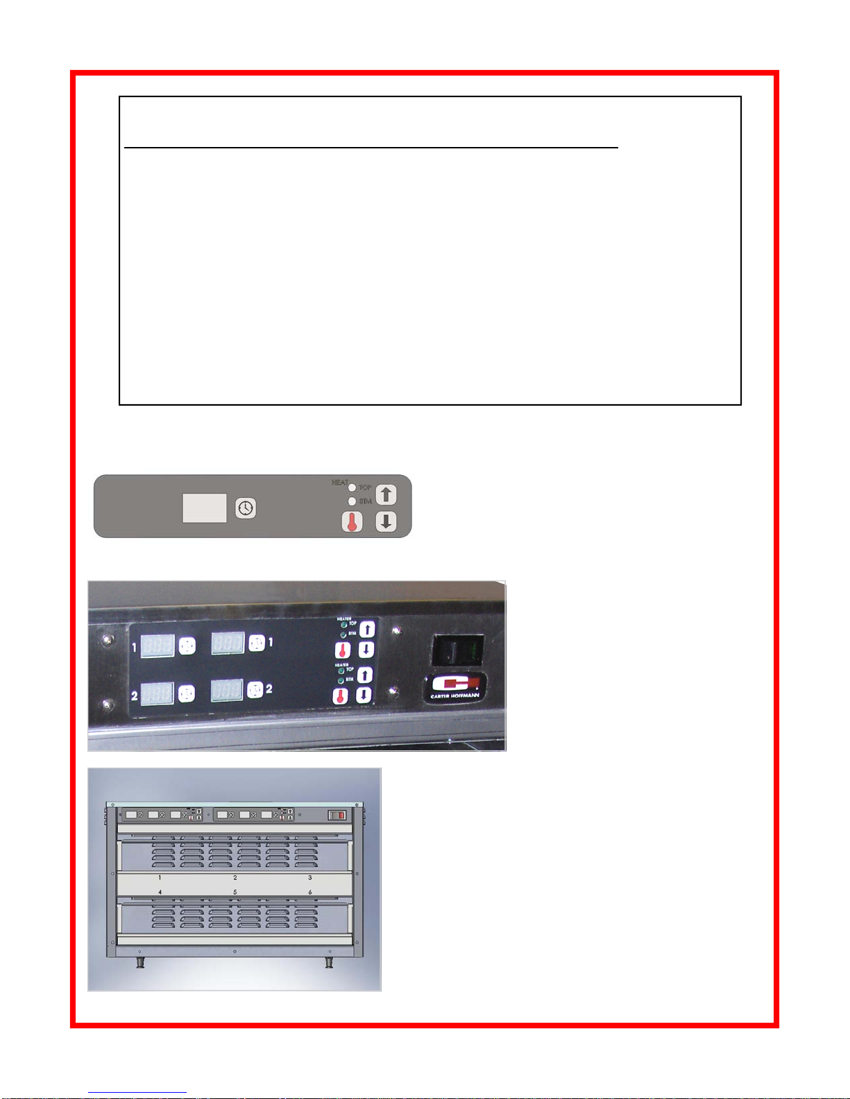
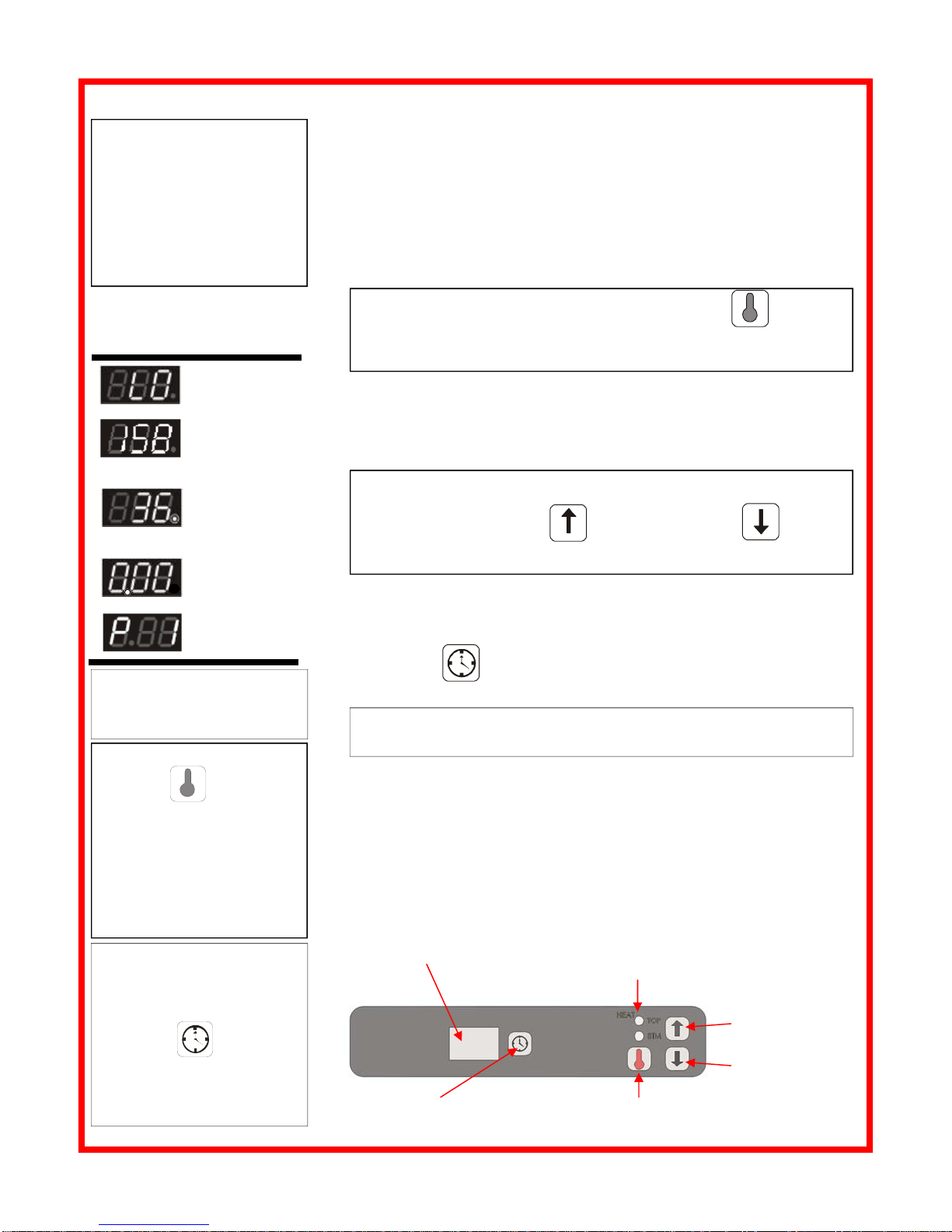
CONTROLLER... Electronic temperature
controls with countdown timer and audio/
visual alarm. One controller per pan cavity.
Allows user to program temperature in one
degree increments up to 225°F (107°C).
Timer can be set for up to 99 minutes, in 1
minute increments. Countdown will convert
to seconds when less than one minute is left.
HEATING SYSTEM... For each module
there are two 200, 250 or 300 watt silicone
pad heater vulcanized to bottom of alumi-
num plate. One mounted to the top of each
cavity and one mounted to the bottom of
each cavity. Programmable controller, with
a digital temperature and time display.
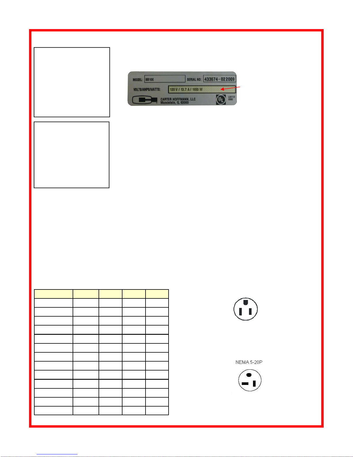
ELECTRICAL CHARACTERISTICS…
Operates on 120 volts, 60 cycle, single
phase, 200, 250 or 300 watts per zone, am-
perage varies in relation to number of zones.
Ten foot 3 wire rubber cord with 3 prong
grounding plug. NEMA 5-15P. MZ423GS-2T
operates on 208v, 2000 watts, 9.6A, NEMA
6-20P. See individual specification sheets for
detailed electrical specifications.
PERFORMANCE...Capable of heating to
195°F (91°C). Temperature default is 195°
F. Preheat to 180°F (82°C) in less than 10
minutes.
OPTIONS & ACCESSORIES...
►Pans with handles (specify size)
►Contact factory for additional non-standard
module configurations
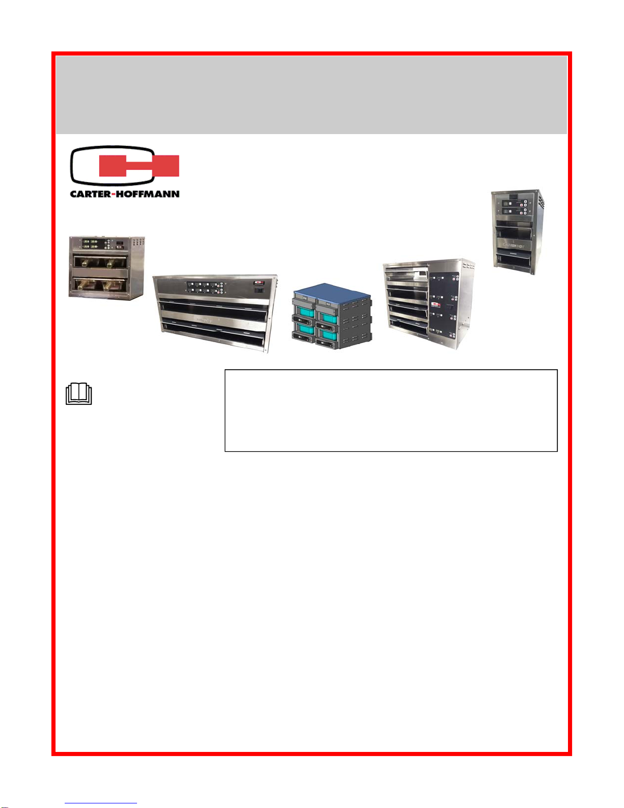
INTRODUCTION
Carter-Hoffmann MZ Modular Holding Cabinets are designed to hold pre-cooked crispy or moist food products at temperature. Hold-
ing times and temperatures are controlled by an electronic controller and are individually programmable for each module. Timer can be
set in one minute increments up to 99 minutes. Temperature can be set in 1ºF increments up to 225ºF (107°C).
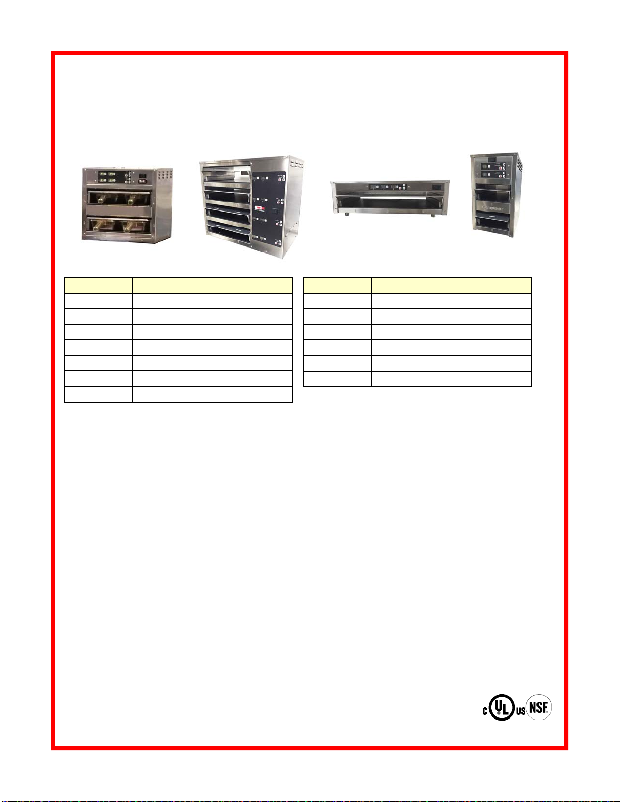
MZ SERIES MODULAR HOLDING CABINET SPECIFICATIONS
MODEL PAN CAPACITY
MZ112S-2T 1 full size, 2 half size or 3 1/3 size (2.5” deep)
MZ212S-2T 2 full size, 4 half size or 6 1/3 size (2.5” deep)
MZ1W2S Two 1/3 size (2.5” deep)
MZ2W2S Four 1/3 size (2.5” deep)
MZ223S-2T Four 1/3 size (2.5” deep)
MZ143S-2T Four 1/3 size (2.5” deep)
MZ243S-2T Eight 1/3 size (4” deep)
MZ223S-2T MZ423GS-2T
MZ112GS-2T
MZ213GS-2T
MODEL PAN CAPACITY
MZ112GS-2T 1 full size, 2 half size or 3 1/3 size (2.5” deep)
MZ212GS-2T 2 full size, 4 half size or 6 1/3 size (2.5” deep)
MZ213S-2T Two 1/3 size (2.5” deep)
MZ223GS-2T Four 1/3 size (2.5” deep)
MZ243GS-2T Eight1/3 size (2.5” deep)
MZ423GS-2T Eight 1/3 size (4” deep)

CLEANING
CAUTION: Unplug cabinet and allow to cool before cleaning.
Daily Cleaning:
1) Turn off cabinet and remove power cord plug from outlet. Allow cabinet
to cool.
2) Remove pans and clean them in the sink with mild detergent and allow
to dry.
3) Wipe cabinet and inside surfaces of warming cavities with a clean
towel moistened with cleaning solution.
4) Rinse by wiping with a clean towel moistened with clean water. Allow
to air dry.
5) Connect power cord.
Weekly Cleaning:
1) Turn cabinet off and remove power cord plug from outlet. Allow cabinet
to cool.
2) Remove pans and pan covers. Reach into cavity and push lid up
while sliding it toward you.
3) Lightly spray cabinet and inside surfaces of warming cavities with
cleaning solution.
4) Wipe cabinet and inside surfaces of warming cavities with a clean
towel until clean. For heavy soils, use a non-scratch or nylon scouring
pad.
5) Rinse by wiping with a clean towel moistened with clean water. Allow
cabinet to air dry.
6) Pans may be cleaned in the sink with mild detergent. Rinse and allow
to air dry.
7) Clean pan covers by wiping with a clean towel moistened with cleaning
solution. On plastic lids, springs may be removed for cleaning; be sure
springs are properly reinstalled. Rinse by wiping with a clean towel
moistened with clean water. Allow to air dry then reinstall in cabinet
with springs positioned “UP”.
8) Connect power cord.
6
CAUTION:
ELECTRIC SHOCK
HAZARD
Disconnect appliance from
electric power before cleaning.
CAUTION:
HOT SURFACE
Exposed surfaces can be hot
to the touch and may cause
burns. Allow appliance to cool
before cleaning.
IMPORTANT:
DO NOT spill or pour
water into controls,
control panel or wiring. Wa-
ter damage is not covered by
warranty.
TYPES OF LIDS: Your cabinet
may have one of two types of
lids, illustrated below:
CAUTION: Cleansers, detergents, degreasers, sanitizers, or
bleaching agents that contain chlorides or phosphates will cause
permanent damage to stainless steel products. The damage
appears as pits, eruptions, voids, small holes, severe discolora-
tion or dulling of the metal finish.
Water with high chloride content can also damage stainless steel. If un-
sure of your water quality, we recommend you have it tested. THIS DAM-
AGE IS PERMANENT, COSTLY TO REPAIR, AND IS NOT COVERED
BY THE WARRANTY.
See next page for tips on cleaning stainless steel.
Oldest Models: Polycarbonate plastic
lid with metal springs
Newer Models:
notched metal
lid over pans
OR
OR
Newest Models: metal
lid over pans with
tabs in front and back

7
RECOMMENDED TIPS FOR CLEANING STAINLESS STEEL
Purpose Frequency Cleaning Agent Method of Application
Routine Daily Soap, ammonia Sponge with cloth, rinse with clear water
cleaningdetergent andwipedry.
andwater
Smears/ As Stainless steel cleaner Rub with soft cloth as directed on package.
Fingerprints needed or similar products Rub in direction of grain of stainless steel.
Donotuseonvinyltrim.
Stubborn Daily Any chloride-free Apply with damp sponge or cloth. Rub in
spots and as or direction of grain of stainless steel. Rinse
stains needed phosphate-free thoroughly, especially if cleaner contains
cleaner chlorine bleach; do not use on vinyl trim.
Hard water Daily Vinegar Swab with cloth.
spots as needed Rinse with water and wipe dry.
FEATURES & OPERATING CONTROLS
MZ223 Controller
2 timers per shelf
Indicator lights for top & bottom heat for
each cavity
MZ1W2S and MZ2W2S Controller
One controller for each cavity
Indicator lights for top & bottom heat for each shelf
MZ212 Controller
3 timers per shelf (some units may have only 1 timer per shelf)
Indicator lights for top & bottom heat for each cavity

TIME KEY
8
NORMAL OPERATION
NOTE: Timer can be
cancelled at any time during
the cycle by
pressing and holding the
TIME KEY for 2
seconds. Digital readout will
display currently selected
timer (e.g “P 1”).
NOTE: Program timer defaults to “P1” each time the unit is turned OFF
then back ON.
NOTE: Timer can not be
started until the cabinet is pre
-heated.
DIGITAL READOUT
INCREASE KEY
DECREASE KEY
TEMPERATURE KEY
NOTE: Press and release
the TEMP key to view
of verify a cavity
setpoint. Cavity setpoint will
be displayed briefly. If the
cavity setpoint needs to be
changed, refer to Program-
ming Instructions on page 9-
10.
1. Press the POWER SWITCH, located at the top front panel, to ON. Illu-
minated portion of switch will glow, indicating power is ON. Pre-heat
cabinet for 20 minutes. When first turned on, digital readout will display
“LO” until the cabinet reaches 122°F (50°C). After the cabinet reaches
122°F (50°C), the digital readout will display the current temperature,
until the temperature reaches the setpoint. Once the cabinet reaches
setpoint, the digital readout will display “P 1”. This indicates the cabinet
is ready to hold product.
Select the desired timer program by pressing the UP / DOWN ARROW
KEYS. Each controller has six programmable timers (“P 1”, “P 2”, “P 3”,
“P 4”, “P 5” and “P 6”) for each group of cavities. Different program times
can be used for different parts of the day (breakfast, lunch, dinner) or for
alternate products.
2. After pre-heat, the digital readout will display the current selected timer
(e.g. “P 1”), indicating that the cabinet is ready to hold product.
3. Load cooked product into pans and place pans on shelves.
4. Press TIME key to start the timer. Refer to Programming
Instructions (page 10) to change programmed time.
Cavity temperature setpoint
range is between 122°F and
225°F (50°C and 107°C)
NOTE: Press and release the appropriate TEMP KEY to view or
verify setpoint. Setpoint will display briefly. If temperature setpoint
needs to be changed, refer to Programming Instructions, page 9.
NOTE: To select other timer programs (“P 2” - “P 6”),
press the INCREASE KEY or DECREASE KEY until the
digital readout displays the desired program.
Typical
temperature
reading
Cabinet is
READY
Tempera-
ture is LOW
5. The digital readout will count down, displaying the remaining time. The
digital readout is displayed in hours and minutes until less than one mi-
nute remains. Once the remaining time is less than one minute, the dig-
ital readout counts down in seconds.
6. At the end of the timed cycle, the digital readout will flash “0.00” and an
alarm will sound until the TIME KEY is pressed.
7. Remove product from cabinet.
8. At the end of the day, or if the cabinet will not be used for an extended
period of time, press the POWER SWITCH to OFF.
Typical Time
Remaining
reading
Timed Cycle
Completed
POWER INDICATING LIGHTS FOR TOP
AND BOTTOM HEATERS (EACH CAVITY)
MOIST FOOD HOLDING IN
MZ CABINETS: Use top and/
or bottom heat with pan lid in
place.
CRISPY / FRIED FOOD
HOLDING IN MZ CABI-
NETS: Use bottom and top
heat and remove pan lid.

9
CONTROLLER PROGRAMMING
To enter into program
mode, display must be in
operating mode and not
in a timing cycle .
NOTE: Each module can
be programmed individual-
ly.
Rear display cannot be
programmed.
TEMPERATURE
SETPOINT RANGE:
122ºF - 225ºF
(50°C - 107°C)
TEMPERATURE
DEFAULT SETPOINT:
195ºF (91°C)
TIMER RANGE:
1 minute to 9 hours, 59
minutes.
NOTE: Timers cannot be
programmed for less than
1 minute.
NOTE: While in the pro-
gram mode, if no key is
pressed for 10 seconds,
any changes will be saved
and the control returns to
normal operation mode.
NOTE:
The technical content of this
manual, including any wiring
diagrams, schematics, parts
breakdown illustrations and/
or adjustment procedures, is
intended for use ONLY by
qualified technical person-
nel.
NOTE:
“P1” must be displayed
before temperature scale
can be changed.
SETTING INDIVIDUAL HEATER TEMPERATURE SETPOINTS
(in programming mode using P1 thru P6
1. With appropriate P# selected, press and hold the TEMP KEY for ap-
proximately 2 seconds, the display will flash the current setting for the lower
heater; the lower heat indicator light will be ON.
2. Press either INCREASE KEY or DECREASE KEY to change
the temperature.
3. To select the upper heater setting, press and release the TEMP
KEY on the upper heat controller. The display will flash the current
setting for the upper heater and the upper heat indicator light will be on.
4. Press either INCREASE KEY or DECREASE KEY to change
the temperature.
5. To select the lower heater setting, repeat steps 3 & 4 for the lower heat
controller.
6. When done, press and hold the TEMP KEY for 2 seconds. Changes
will be saved. If no button is pressed, controller will automatically exit and
changes will be saved.
NOTE: If no key is pressed for 5 seconds, display returns to “P 1”. Chang-
es will be saved.
NOTE: If P1 is not displayed, press ARROW KEY
DIGITAL READOUT
INCREASE KEY
DECREASE KEY
TEMPERATURE KEY
TIME KEY
POWER INDICATING LIGHTS FOR TOP
AND BOTTOM HEATERS (EACH CAVITY)
Continued on next page

10
CONTROLLER PROGRAMMING (continued)
TO CHANGE THE TEMPERATURE SCALE
Press the TEMP KEY until the temperature starts flashing. Then, press
both the up and down arrow buttons (together) until ‘F’ (Fahrenheit) is dis-
played.
Press the up or down arrow keys to toggle between ºC and ºF.
Once selected, press the TEMP KEY to save and exit.
To enter into program
mode, display must be in
operating mode and not
in a timing cycle .
NOTE: Each module can
be programmed individual-
ly.
Rear display cannot be
programmed.
TEMPERATURE
SETPOINT RANGE:
122ºF - 225ºF
(50°C - 107°C)
TEMPERATURE
DEFAULT SETPOINT:
195ºF (91°C)
TIMER RANGE:
1 minute to 9 hours, 59
minutes.
NOTE: Timers cannot be
programmed for less than
1 minute.
NOTE: While in the pro-
gram mode, if no key is
pressed for 10 seconds,
any changes will be saved
and the control returns to
normal operation mode.
NOTE:
The technical content of this
manual, including any wiring
diagrams, schematics, parts
breakdown illustrations and/
or adjustment procedures, is
intended for use ONLY by
qualified technical person-
nel.
PROGRAM TIMERS (P1 through P6)
1. Press and hold TIME KEY until digital readout flashes.
2. Press INCREASE KEY to add time. Each time key is pressed, timer
is increased by 1 minute. Hold key to scroll faster.
3. Press DECREASE KEY to subtract time. Each time key is pressed,
timer is decreased by 1 minute. Hold key to scroll faster.
4. Press TIME KEY to save changes and return to P1.
5. To program timers P2 through P6:
A. Press INCREASE KEY or DECREASE KEY to select the
desired program.
B. Repeat steps 1 through 4 above for each program
TO CANCEL TIMER: Press and hold TIME KEY for 2 seconds.
DIGITAL READOUT
INCREASE KEY
DECREASE KEY
TEMPERATURE KEY
TIME KEY
POWER INDICATING LIGHTS FOR TOP
AND BOTTOM HEATERS (EACH CAVITY)
NOTE:
“P1” must be displayed
before temperature scale
can be changed. If “P1” is
not displayed, press
ARROW KEY to display
“P1.”

11
Modular Food Holding Guide*
Product Temperature
(°F/ °C) Maximum Recommended
Hold Time (minutes) With Humidity
(water layer under trivet)
Hamburger Patties 175 / 79 30 No
Crab Legs / Shrimp 160 / 71 45 Yes
Macaroni & Cheese 175 / 79 120 No
Baked Beans / Chili 180 / 82 120 No
Omelets 175 / 79 45 Yes
Egg Bake / Quiche 165 / 74 120 No
Hash Brown Potatoes 180 / 82 60 No
Sausage Patties 180 / 82 60 No
Biscuits (bottom heat only; no lid) 165 / 74 30 No
Tortillas, Soft 180 / 82 60 No
Croissants 170 / 77 60 No
French Toast 165 / 74 60 No
Pancakes 180 / 82 30 No
Scrambled Eggs 180 / 82 60 No
Hot Dogs 180 / 82 180 Yes
Lasagna 170 / 77 60 No
Pasta 175 / 79 60 No
Rice 175 / 79 30 No
Vegetables 175 / 79 45 No
Bacon, Crisp (top & bottom heat; no lid) 180 / 82 30 No
Bacon, Canadian 180 / 82 30 Yes
Nacho Cheese 165 / 74 240 No
Cut Green Beans / Mixed Vegetables 160 / 71 240 No
Chops. Sliced Meats 160 / 71 60 Yes
Chicken, Fried (top & bottom heat; no lids) 170 / 77 30 No
Chicken, Boneless Breasts 175 / 79 60 Yes
Chicken Breasts, Grilled 170 / 77 150 Yes
Chicken Nuggets, Breaded (top & bottom heat;no lid) 190 / 88 25 No
Chicken, Pre-Cooked Boneless Patties 150 / 66 90 Yes
Fish, Fried (top and bottom heat; no lid) 170 / 77 30 No
Fish, Baked or Broiled 155 / 68 45 Yes
Pork Loin Roast, Whole 180 / 82 60 Yes
Ribs, In Sauce 175 / 79 90 No
Paella 180 / 82 60 No
Gravies, Sauces 170 / 77 45 No
Soups 185 / 85 90 No
Poppers, Fried (top & bottom heat; no lid) 190 / 88 25 No
*NOTE: Times and temperatures
observed in a test kitchen envi-
ronment. Times & temperatures
may vary, depending on initial
food quality, initial cooked tem-
perature and user expectations of
acceptable quality. Holding times/
temps for products with bottom
heat and lids, unless otherwise
noted.
MOIST FOOD
HOLDING IN MZ
CABINETS: Use top
and/or bottom heat
with pan lid in place.
CRISPY/FRIED
FOOD HOLDING IN
MZ CABINETS: Use
bottom and top heat
and remove pan lid.

SERVICE EXPECTATIONS
12
Service Philosophy
For over sixty years, Carter-Hoffmann has earned a reputation for manufacturing rugged and
dependable foodservice equipment that permits foodservice professionals serve better food
products to more people, and thus, grow their business.
Our goal is not only to provide the best food service equipment for the price, but also to back it up
with after-sale service that is responsive, fast, efficient and professional. Carter-Hoffmann products
are innovative and efficient. They are easy to use, easy to clean and easy to maintain. Although the
products are quite reliable, they are also designed to be easy to repair when necessary.
We believe that a malfunction to a Carter-Hoffmann product should cause as little inconvenience to
the customer as possible. Our goal is to provide the same day service or within 24 hours and strive
to fix it the first time. We are dedicated to making every aspect of our customer service the standard
by which others are judged.
End-User Responsibilities
While we all strive to serve our mutual customers as well as possible, we remind the end-user
(and their employees) that they also have some responsibilities.
1. All shipping damage must be noted on the freight bill when the shipment is received. Any freight
damages must be collected from the Freight Company, NOT Carter-Hoffmann.
2. The end-user should be advised beforehand to carefully unpack and inspect all products when
they are received BEFORE SIGNING THE SHIPPER'S RECEIPT OF DELIVERY.
3. The end-user must provide a safe, dry, level surface for the equipment to be placed upon.
4. The end-user must provide the proper electrical supply. All in-wall electrical modifications are to
be completed by a licensed electrician. All building modifications are the responsibility of the end
-user. Specification literature changes frequently, please verify proper installation is possible.
5. The end-user must operate, clean and maintain the equipment in accordance with the
procedures described in this Operation Manual.
6. Carter-Hoffmann is NOT responsible for any loss of the customer’s income, loss of food product,
extra labor charges, or any other incidental or consequential costs as a result of the malfunction
of our product.
7. The end-user shall allow for on-premises repair of the equipment to be completed at a mutually
convenient place and time.
Warranty Service
1. Warranty service is to be initiated by authorized Carter-Hoffmann personnel only, please call
Carter-Hoffmann directly and we will take care of everything.
2. The service provider is NOT authorized to change or extend any of the terms or conditions of our
warranty.
3. Initial freight damage is NOT covered by the product warranty.
Confidentially
1. The end user and all his employees and sub-agents shall protect and keep confidential Carter-
Hoffmann’s proprietary designs, information, and knowledge.
2. All literature and informational materials provided by Carter-Hoffmann are to be considered
confidential; they remains Carter-Hoffmann’s property; and are not to be reproduced without our
prior approval
NOTE:
The technical content of this manual, including any wiring diagrams, schematics, parts breakdown illustrations
and/or adjustment procedures, is intended for use ONLY by qualified technical personnel.

12
Carter-Hoffmann
1551 McCormick Ave.
Mundelein, Illinois, 60060 USA
Phone: 847-362-5500 Toll free: 800-323-9793 Fax: 847-367-8981
Sales and Marketing E-mail: sales@carter-hoffmann.com
Company Website: www.carter-hoffmann.com
Carter-Hoffmann Warranty:
Carter-Hoffmann (“CARTER-HOFFMANN”) warrants to the initial purchaser of its standard Carter Line Prod-
ucts that CARTER-HOFFMANN will, at its option, repair or replace, during the warranty period set forth below,
any part of such products made necessary due to a defect in material or workmanship which is present when the
product leaves its factory and which manifests itself during the warranty period under normal use and service.
This warranty applies only to original equipment owned and possessed by the initial purchaser and the warranty
period begins on the date of original shipment from the CARTER-HOFFMANN factory and extends as follows: to
component parts and labor for 12 months.
Repair or replacements under this warranty will be performed, unless otherwise authorized in writing by CARTER
-HOFFMANN, at its factory. All parts or components to be repaired or replaced under this warranty are to be
shipped prepaid to CARTER-HOFFMANN, with reimbursement credit for such part or component to be given if
found by CARTER-HOFFMANN to be defective.
CARTER-HOFFMANN neither makes nor assumes and does not authorize any other person to make or assume
any obligation or liability in connection with its products other than that covered in this warranty. This warranty
applies only within the continental United States and Canada. In Alaska and Hawaii, this warranty applies only to
and is limited to the supply of replacement parts.
Warranty Exclusions and Limitations:
Any implied warranty of merchantability or fitness for a particular purpose is hereby specifically disclaimed by
CARTER-HOFFMANN. There are no warranties, expressed or implied, which extend beyond the description on
the face hereof. This warranty does not cover and CARTER-HOFFMANN shall not under any circumstances be
liable for any incidental, consequential or other damages (such as injury to persons or property, loss of time, in-
convenience, loss of business or profits, or other matters not specifically covered) arising in connection with the
use of, inability to use, or failure of these products.
Specifications are subject to change through product improvement and innovation.
This manual suits for next models
17
Table of contents
Other CARTER-HOFFMANN Food Warmer manuals
Popular Food Warmer manuals by other brands

Avantco Equipment
Avantco Equipment 177W800 120 user manual

Vollrath
Vollrath Mirage 74701DW Operator's manual

Amba
Amba RADIANT RSWH-P installation instructions

Hatco
Hatco PW Series Installation and operating manual

Frymaster
Frymaster Heated Landing Zone HLZ Operator's manual

Ancona
Ancona Comfort 5 Installation and operation manual