CARVIN BR12 User manual

CARVIN ENGINEERING DATA BR12 and BR15 BASS AMPS OPERATING MANUAL
Congratulations on your purchase of the Carvin BR12/BR15 bass
amplifier. For over 40 years we have been building bass amplifiers,
so you can expect award-winning performance from these compact pro-
fessional bass systems.
BASS SIGNAL PROCESSING
The preamp of a bass amplifier is the key to great tone. The first item
in the amp’s signal chain is the internal Class A discrete preamp cir-
cuits. Class A preamps circuits are renown for their superior sonic
detail. Secondly, your BASS, MID sweep & TREBLE controls are pow-
erful active circuits, which will add flexibility in generating your tone.
The BX120 head also features a 5 BAND GRAPHIC EQ allowing you to
put the final touches on your sound from specialized filters designed
just for the bass guitar.
The BR12 and BR15 continues with features that are only found in
the most comprehensive bass rigs. A COMPRESSOR, which is sought
out by most professionals, is featured because it controls the over-
all level of the amp regardless of where the volume control is set. You
can now control your peaks without the amp getting too loud or keep
the amp from distorting.
You may easily add to your signal processing with an effects proces-
sor to enhance your sound. Any device from a foot pedal to a full effects
rack can be plugged into the rear of the “buffered” Send / Receive
EFFECTS LOOP.
The preamp LINE/PHONES jack can also be used as a main output
from the preamp to send your signal to a mixing console or another
high powered amplifier, allowing you to use the full complement of
signal processing from your unit.
COMBO CABINET DESIGN
Part of the success of the BR12/BR14 combo amplifiers are their light-
weight design and high performance. A cabinet tuned to the speak-
ers parameters in each system adds to the speaker’s efficiency in the
35 Hz to 50 Hz range, resulting in overall warmth and a bigger,
rounder sound. The BRseries combo’s also feature a 1”Titanium HF
Driver to extend the upper range to 16k Hz, enhancing the harmonics
Specifications:
Freq. Response: 20 Hz to 20k Hz ±3 dB
THD: Typically less than .1%
RMS Power: 120 watts @ 4 ohms
Direct Out: XLR jack, GND Lift, and Level
Contour: FLAT to 250Hz/-8DB MID Cut
Tone Controls: LO: 80Hz ±12dB
(3 band with mid sweep) MID: 200-2KHz ±12dB
HI: 8KHz ±12dB
Compressor: up to 30dB reduction
Comp Thresh/Ratio: -7 to -27 dB, 3:1 ratio
5 Band Graphic EQ: 80Hz, 250Hz, 500Hz,
800Hz, & 2kHz, ±12dB
Cabinet Freq. Resp: BR12: 50 Hz to 16k Hz BR15: 41 Hz to 16k Hz
Cabinet Types: Sealed enclosure
Cabinet Construction: Baltic Birch Plywood
Tweeter Attenuation: Continuously variable
Warranty: One Year
Power Requirements: 120VAC, 225VA
240VAC, 225VA
Fuse: 5A 250V slow blow
Size and Weight BR12: 17.5Wx12Dx25H. 36 lbs. BR15:19.3Wx14.9Dx24H. 46 lbs.
Footswitch: FS22, mute and EQ
76-42120A 1106
12340 World Trade Drive, San Diego, CA 92128
800.854.2235 www.carvin.com
for percussive slap. The 1” Titanium HF Driver is fully adjustable from
a variable rear control. All enclosures are covered in durable black
DuraTuff II™ for your transporting protection.
POWER AMP
Pure, clean bass power is delivered to your speaker from the
BR12/BR15 series ultra-low distortion power amp. Turn-on muting,
short circuit and thermal overload circuits protect your speakers and
amp form accidental overloads. ( Note: It is normal for the amp to
get warm to the touch).
RECEIVING INSPECTION—read before getting started
INSPECT YOUR AMP FOR ANY DAMAGE which may have occurred during shipping.
If any damage is found, please notify the shipping company and CARVIN immediately.
SAVE THE CARTON & ALL PACKING MATERIALS. In the event you have to re-ship your
unit, always use the original carton and packing material. This will provide the best pos-
sible protection during shipment. CARVIN and the shipping company are not liable for
any damage caused by improper packing.
SAVE YOUR INVOICE. It will be required for warranty service if needed in the future.
SHIPMENT SHORTAGE. If you find items missing, they may have been shipped sepa-
rately. Please allow several days for the rest of your order to arrive before inquiring.
RECORD THE SERIAL NUMBER on the enclosed warranty card or below on this manual
for your records. Keep your portion of the card and return the portion with your name
and comments to us, or you may register online at www.carvin.com/registration.
GETTING STARTED QUICKLY
Turn the amp on and volume off, set the tone controls at their mid
“0” center position, turn the compressor and noise gate off and set
the 5 band graphic EQ to the their center/mid positions. Plug your
amp into the AC voltage and then plug in your bass. Now, turn the
amp’s power switch ON and gradually raise the volume. Re-adjust
the contour and tone controls as needed and your ready to go.
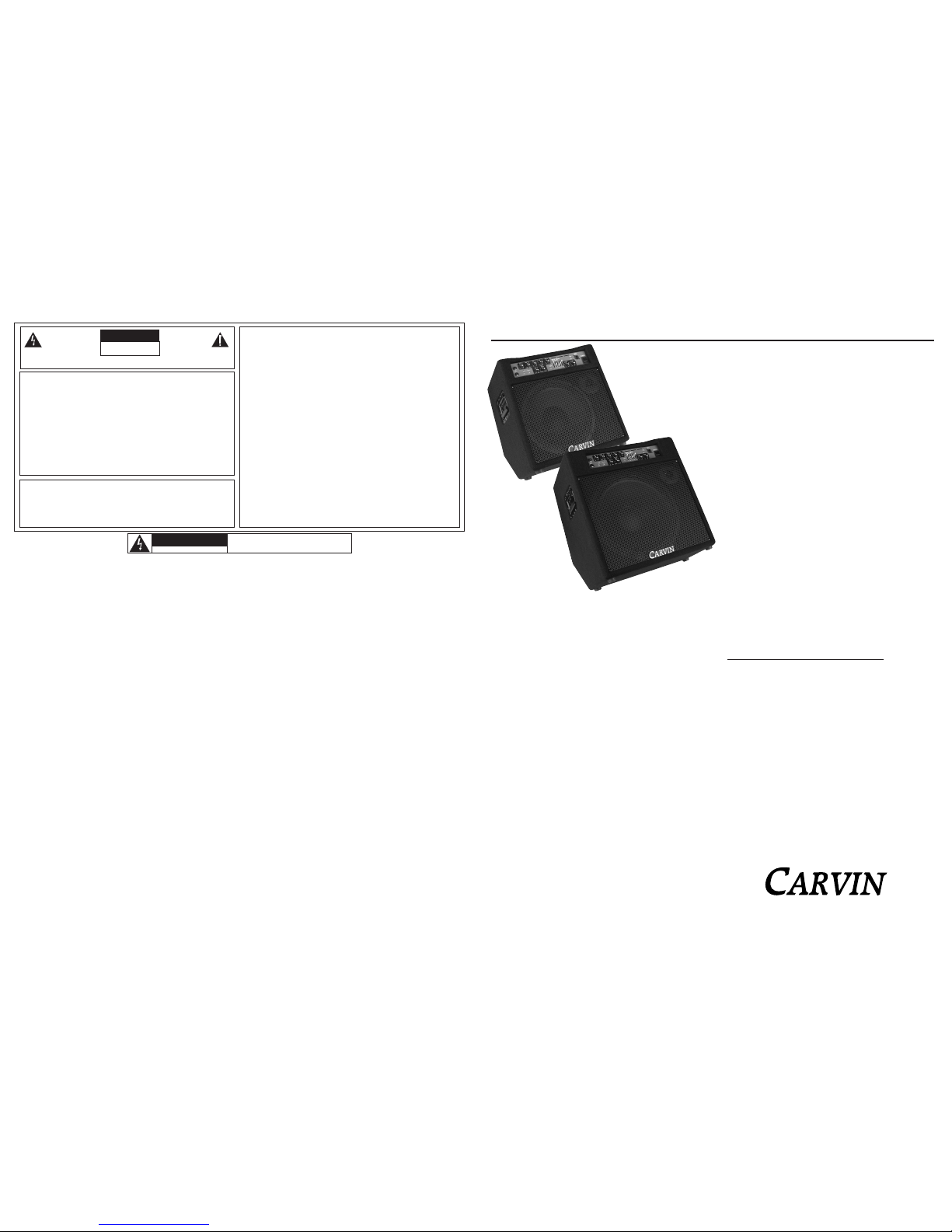
BR15
For your records, you may wish to record the following information.
Serial No._____________________ Invoice Date_______________
BR12
SAFETY INSTRUCTIONS (EUROPEAN)
The conductors in the AC power cord are colored in accordance with the following code.
GREEN & YELLOW—Earth BLUE—Neutral BROWN—Live
U.K. MAIN PLUG WARNING: A molded main plug that has been cut off from the cord is
unsafe. NEVER UNDER ANY CIRCUMSTANCES SHOULD YOU INSERT A DAMAGED
OR CUT MAIN PLUG INTO A POWER SOCKET.
IMPORTANT! FOR YOUR PROTECTION, PLEASE READ THE FOLLOWING:
WATER AND MOISTURE: Appliance should not be used near water (near a bathtub, washbowl,
kitchen sink, laundry tub, in a wet basement, or near a swimming pool, etc). Care should be taken
so that objects do not fall and liquids are not spilled into the enclosure through openings.
POWER SOURCES: The appliance should be connected to a power supply only of the type described
in the operating instructions or as marked on the appliance.
GROUNDING OR POLARIZATION: Precautions should be taken so that the grounding or polar-
ization means of an appliance is not defeated.
POWER CORD PROTECTION: Power supply cords should be routed so that they are not likely
to be walked on or pinched by items placed upon or against them, paying particular attention
to cords at plugs, convenience receptacles, and the point where they exit from the appliance.
SERVICING: The user should not attempt to service the appliance beyond that described in the
operating instructions. All other servicing should be referred to qualified service personnel.
FUSING: If your unit is equipped with a fuse receptacle, replace only with the same type fuse.
Refer to replacement text on the unit for correct fuse type.
REFER SERVICING TO QUALIFIED SERVICE
PERSONNEL! THIS UNIT CONTAINS HIGH
VOLTAGE INSIDE!
CAUTION
RISK OF ELECTRIC SHOCK
LIMITED WARRANTY
Your Carvin product is guaranteed against failure for ONE YEAR unless otherwise stated. Carvin will
service and supply all parts at no charge to the customer providing the unit is under warranty. Shipping
costs are the responsibility of the customer. CARVIN DOES NOT PAY FOR PARTS OR SERVICING OTHER
THAN OUR OWN. A COPY OF THE ORIGINAL INVOICE IS REQUIRED TO VERIFY YOUR WARRANTY.
Carvin assumes no responsibility for horn drivers or speakers damaged by this unit. This warranty
does not cover, and no liability is assumed, for damage due to: natural disasters, accidents, abuse,
loss of parts, lack of reasonable care, incorrect use, or failure to follow instructions. This warranty
is in lieu of all other warranties, expressed or implied. No representative or person is authorized to
represent or assume for Carvin any liability in connection with the sale or servicing of Carvin prod-
ucts. CARVIN SHALL NOT BE LIABLE FOR INCIDENTAL OR CONSEQUENTIAL DAMAGES.
When RETURNING merchandise to the factory, you may call for a return authorization number. Describe
in writing each problem. If your unit is out of warranty, you will be charged the current FLAT RATE for
parts and labor to bring your unit up to factory specifications.
HELP SECTION
1) AMP WILL NOT TURN ON
Check the power to the amp. Check for tripped circuit breakers, unplugged extension cords or power-
strip switches that may be turned off. Check the fuse. If a dark brownish color or no wire can be
seen within the glass tube, then replace. The amp may be perfectly fine but occasionally a fuse
may blow because of high AC voltage surges. After the fuse has been replaced with the proper
Slow Blow value and if the fuse fails again, the amp will require servicing.
2) NO OUTPUT with POWER LED light ON
Check the speaker cable. If OK, it’s possible that a speaker jack is defective. Check the SEND &
RETURN jacks as one of these jacks could be defective. Insert a guitar cord between these two
jacks to test. Defective jacks will require servicing.
3) KEEP YOUR AMP LOOKING NEW
Use a damp cloth to wipe the controls on the front & rear chassis panels. Wipe dry! Brush the lint
off the Duratuff II™ covering.
CAUTION
RISK OF ELECTRIC SHOCK
DO NOT OPEN
This symbol is intended to
alert the user to the pres-
ence of uninsulated “dan-
gerous voltage” within the
product’s enclosure that may be of suf-
ficient magnitude to constitute a risk of
electric shock to persons.
This symbol is
intended to alert the
user to the presence of
important operating
and maintenance (servicing) instruc-
tions in the literature accompanying
the appliance.

1.
INPUT JACK
The 1/4" phone jack is an instrument input designed to handle both active and
passive basses in connection with the Active Switch.
2. BLUE JEWEL LIGHT
The Blue jewel light indicates the power is on.
3. DRIVE CONTROL
The DRIVE control adjusts the input level to the class A preamps. The Drive
control serves two purposes. The first half of the knob, 0-5, can be used to adjust
the input sensitivity for the differences in bass pickups. The second half of the
knob, 5-10, will increase the harmonic content of the tone. The closer to 10 the
more overdrive the tone will become. The drive knob will increase the volume
of the amplifier, so use it in combination with the master volume to achieve the
desired amplifier volume.
4. MUTE SWITCH
The MUTE switch mutes the output of the amplifier. A blue LED indicates the
MUTE switch is on. The mute switch is ideal for changing basses while the amp
is on and silent tuning on stage, since the rear tuner output is not muted. The
mute feature can also be switched with an FS22 footswitch.
5. ACTIVE SWITCH
Flip the active switch to the down “OFF” position for standard passive bass
pickups. If your bass uses a battery with an onboard active preamp, put the switch
in the up position. A blue LED indicates the ACTIVE switch is on.
6. CONTOUR CONTROL
The contour control provides a variable mid range scoop. When this control is
set to “FLAT” there is no change to the mid range frequencies. As you turn the
contour control clockwise, a mid range cut is scooped at 250Hz. When the con-
tour control is set to maximum, the mid-range is cut at -9dB at 300Hz.
7. BASS AND TREBLE TONE CONTROLS
The BASS and TREBLE tone controls are custom shaped controls to deliver punchy
lows and crisp tight highs for a variety of bass sounds.
When the BASS control is turned to the right, it boosts the signal and when
turned to the left cuts the signal. The effected frequencies are centered at 80Hz
and can deliver a great deal of volume. Be careful not to distort the output.
When the TREBLE control is turned to the right, it boosts the signal and when
turned to the left, it cuts the signal. The boosted frequency for the TREBLE con-
trol is centered at 8k Hz.
8. MID SWEEP TONE CONTROLS (GAIN & FREQ.)
These two controls will take some time to learn how to use. First, the FREQ.
control does not function if the GAIN control is set in the center “0” position. To
demonstrate, turn the GAIN to the right for full boost. Now turn the FREQ. con-
trol from full left to full right and notice the added mids change frequencies as
you play your bass. Now turn the GAIN to the full left and re-sweep the FREQ.
control and notice the mids disappear at different frequencies. There are many
variables as you can hear, so write down some of the settings for future refer-
ence. The mid sweep system is designed for fine tuning your overall sound.
9. COMPRESSOR (COMP)
For some people, a compressor is a new feature. What it basically does is reduce
(or compress) the volume of the incoming signal to conform to a preset maxi-
mum output level. This describes the COMP knob in the full-clock wise posi-
tion where it functions as a limiter. As the knob is turned back (counter
clockwise) the compressor lets a larger and larger percentage of the incoming
signals to pass through. This is raising the threshold of where the compressor
turns on. The maximum compression ratio is 3:1.
The advantages of a compressor is to increase the overall level of playing (or
the average level) and not have peaks or other sudden loud parts (transients).
For example, in slap bass playing, the plucked notes can put out peaks that could
distort the amplifier at normal playing volumes. On the other hand, if the ampli-
fiers volume was adjusted for these peaks, the rest of the notes would be too
quiet to hear. Now, when the compressor is adjusted to where the indicator LED
comes on when the peaks are present, the amplifier can be played louder and
still reduce the peaks without distortion. It’s like having someone constantly and
instantly re-adjusting the volume of the amplifier to prevent distortion when the
peaks occur.
The Compressor circuit is also internally connected to the power amplifier. When
the amplifier reaches a distortion level that maybe harmful to speakers it acti-
vates the compressor to reduce the input signal. This in turn takes the amplifier
out of distortion and protects the speakers even when the compressor control
is set to “0”.
10. 5-BAND POST SHAPE EQUALIZER AND EQ IN SWITCH
5 band’s of the GRAPHIC EQ have been custom shaped and selected for the
bass guitar. The levels and tonal shaping of each band are customized individ-
ually unlike a standard graphic EQ to increase its usefulness and sweeten the sound
of each band. Here are some references for the individual sliders to help relate
the frequencies in hertz to perceived sounds.
• The 80Hz slider is for the ultra lows. Often used in the cut region to boost or
reduce the low end.
• The 250 Hz slider is for the mid-low bass. The bass has a great deal of sound
here, so this slider can change the sound drastically. Slide it up and down to
hear what you like.
• The 500Hz slider is for the mid-bass frequencies. Like the 250Hz slider, there
is a great deal of bass guitar here also.
• The 800Hz slider is for the bass guitar’s high mids. This is where the mids start
to get snappy, but they can also get honky.
• The 2KHz slider is for the bass guitar’s highs. The crispy high’s in slap bass
playing start in the range of this slider.
FRONT & REAR PANEL CONTROLS
12345 6 7 789 10 11 12
19
ADJUSTING THE GRAPHIC EQ SLIDERS:
The best way to use the GRAPHIC EQ is to set all the sliders to their center
detent positions. When the sliders are in this position, they do no affect the audio
signal. After playing in this “flat” setting for a few minutes, raise one slider (to
boost) and play a broad range of notes to hear the change. Then lower the same
slider pass the center detent (to cut), play a few notes to hear the change and
return the slider to the center position. Try this with each slider to hear what
they do, then go back and adjust them together if needed for your sound.
EQ IN switch: when the blue LED is lit the Graphic EQ is in and will effect the
sound of the amplifier. The Graphic EQ can also be switched in and out with an
FS22 footswitch.
11. MASTER VOLUME
The master is the last volume control of the amplifier. This is where overall level
of the amplifier is set. The master volume also effects the headphone output.
12. DI LEVEL & DI XLR OUTPUT
The BR series provides this professional feature only found on our larger bass
amplifiers. The direct output is used to send a direct signal to the main PA system
or a recording track. The signal is a buffered and balance version of the signal
straight from the input jack. Use the DI level control to adjust the output level
of the direct output, and use the Ground lift switch to break a ground loop buzz
caused by creating power ground loops through making the direct output con-
nection to the PA system.
13. POWER SWITCH
The power switch turns on the amplifier and is indicated by the large blue jewel
light over the input jack.
14. HEADPHONE/LINE OUT JACK
The 1/4” jack can be used for mono headphone or a line output to feed a mixer
or power amp.
15. SEND JACK (EFFECTS LOOP)
The SEND jack is the output of the preamp. This jack, used in conjunction with
the RETURN jack, makes up the external effects loop. The SEND jack is
designed to put out the proper level for the input of an external effects proces-
sor.
16. RETURN JACK (EFFECTS LOOP)
The RETURN jack completes the effects loop in conjunction with the SEND jack.
This jack is designed to receive signals from an external effects processor. When
something is plugged into this jack it goes directly into the power amp portion
of the bass amplifier and breaks the connection between the bass preamp and
the internal power amp.
17. SPEAKER OUTPUT JACK(S)
There are 2 speaker output jacks designed for a total minimum impedance of 4
ohms.
18. AC POWER
The detachable AC POWER CORD supplied is designed to operate with one type
of voltage (the European 230V export model uses a CEE-7 plug cord set). Check
the rear power cord label for the proper voltage. Plug the cord into a grounded
“3” prong” power source. No attempt should ever be made to defeat or use the
amp without the ground connected.
19. HF DRIVER LEVEL CONTROL (ENCLOSURE)
In the back of the BR12 and BR15 there is a small jack plate with a level knob
for the HF Driver. This level control adjusts the volume of the HF Driver and
does not effect the 15” woofer.
The HF Driver level control is another way to increase or decrease the highs
coming from your bass. If more highs are desired, the HF Driver level can be
turned up (clock wise), or turned off if a warmer sound is desired.
Note: One thing to consider with the HF Driver volume is the direction the cab-
inet is facing. Because the combo amplifier’s HF Driver is less than two feet
off the ground, the listeners seated in front of the amplifier may be getting more
of the HF Driver volume than you (the player) standing in front of the amplifier.
So be conscious of the volume and direction of the HF Driver when adjusting.
17
19 19 15 16
This manual suits for next models
1
Other CARVIN Musical Instrument Amplifier manuals

CARVIN
CARVIN VT50 User manual

CARVIN
CARVIN R1000 III User manual

CARVIN
CARVIN GC212C User manual

CARVIN
CARVIN V3 User manual

CARVIN
CARVIN X-100B User manual

CARVIN
CARVIN B500 User manual

CARVIN
CARVIN MTS3200 User manual

CARVIN
CARVIN X-100B User manual

CARVIN
CARVIN Vintage 16 User manual

CARVIN
CARVIN SX-100D User manual