CARVIN XDrive XD88 User manual

1
XD88 Operation Manual
The XD88 Extreme Drive is designed to provide incredible flexibility, sonic excellence
and intuitive controls for loudspeaker and EQ management. The XD™ software with its
USB PC connectivity offers total control of your system with all the processing flexibility
necessary for both installation and live use. The XD88 is the next generation tool for
sound processing that is needed between the mixer and power amp.
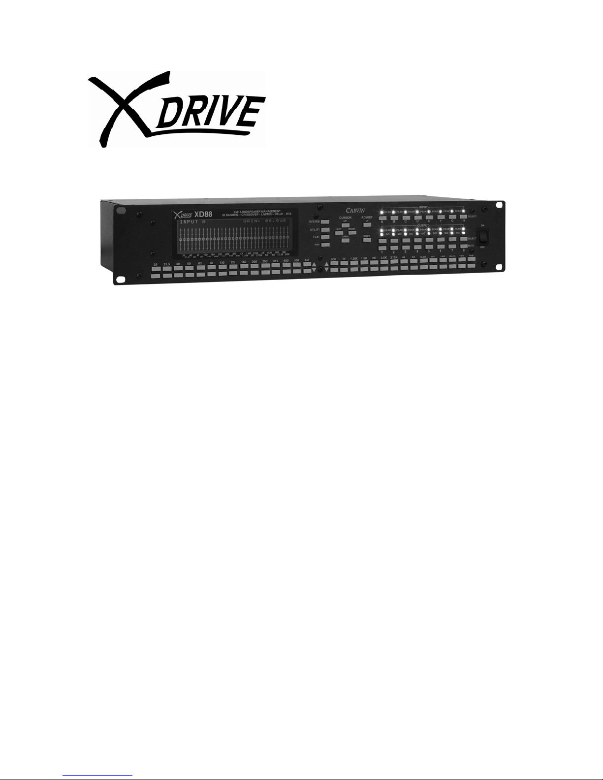
Eight analog inputs and outputs make the XD88 one of the most powerful management
tools on the market today. The flexible matrix routing allows any of the 8 inputs to be
assigned to any of the 8 outputs, plus any multi-channel combination. As a primary
loudspeaker management system, the XD88 can control systems from 8 mono full-range
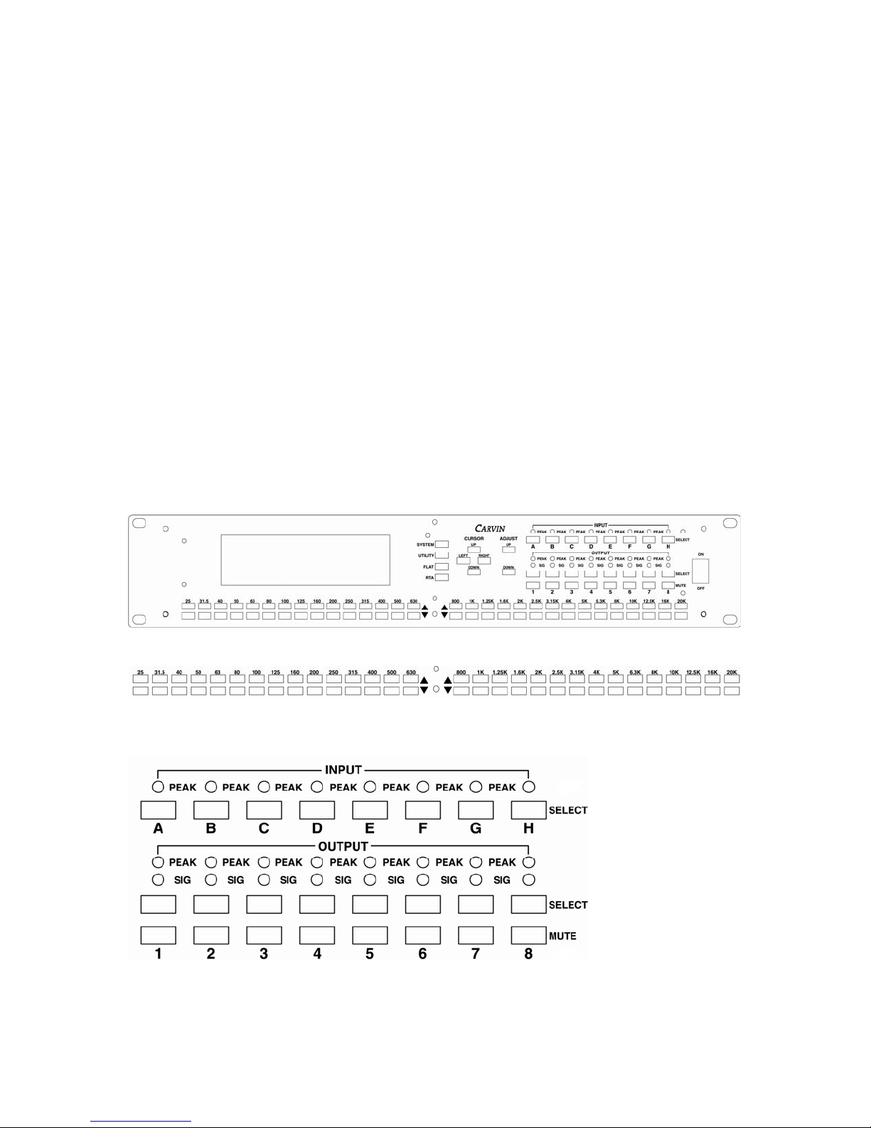
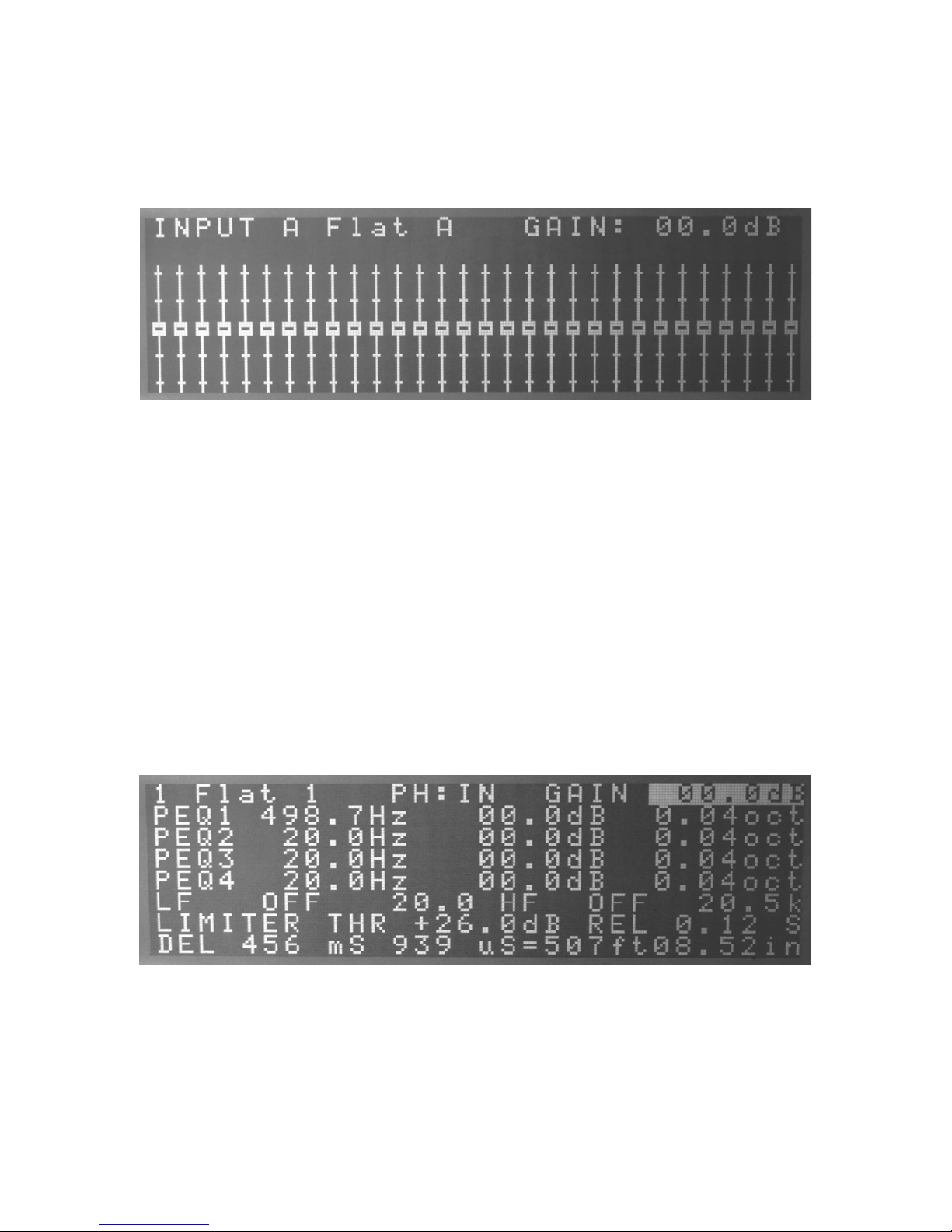
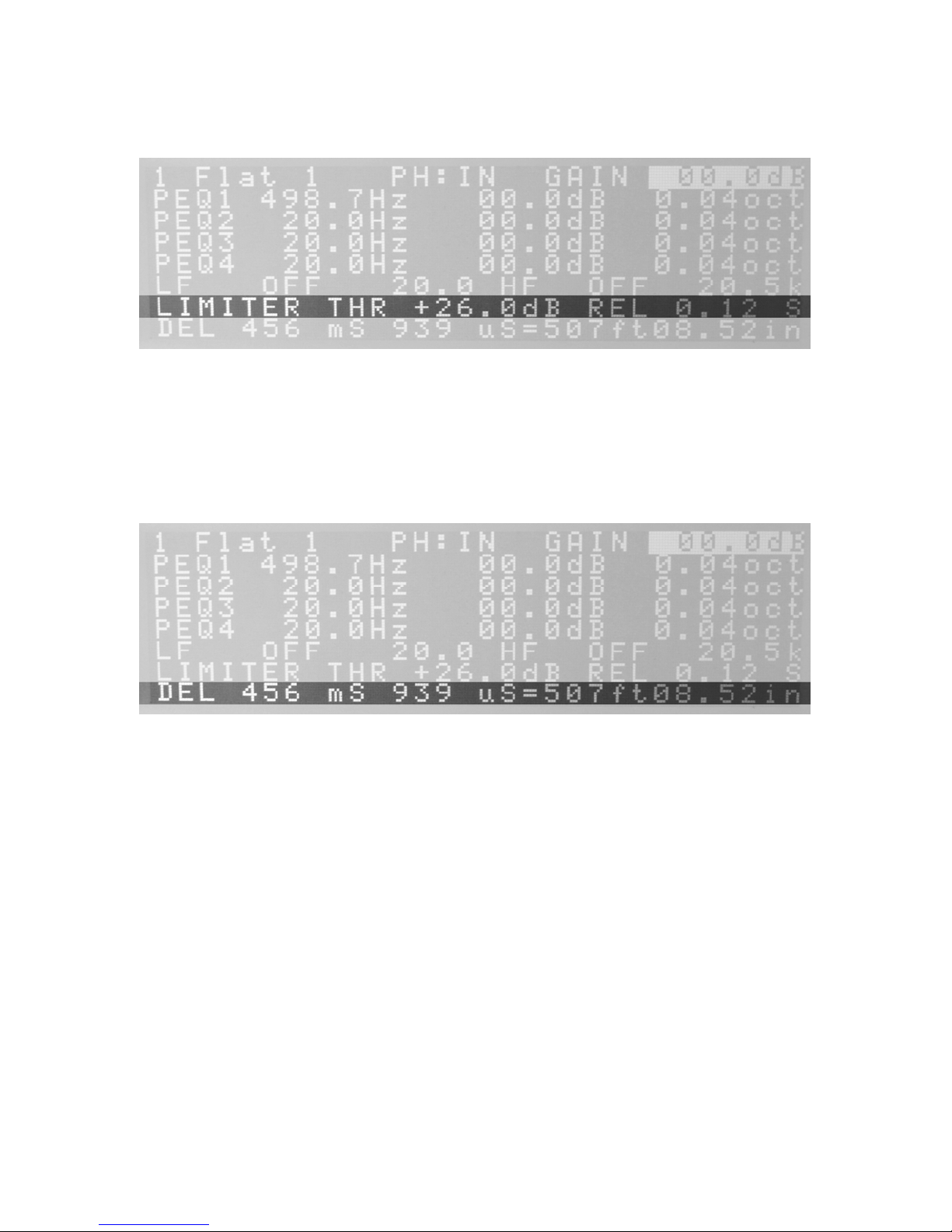
channels to stereo 4-way and everything in between. Other useful features include: 30
Band Graphic equalizers on each input with 60 instant access buttons for up/down of
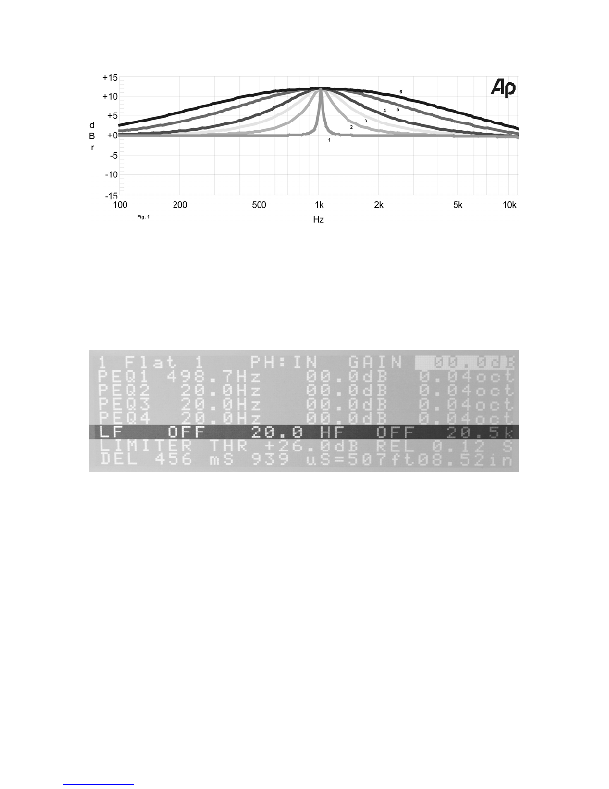
each fader band. Each output has 4 parametric EQ’s, high and low crossover filters
(Bessel, Butterworth, Linkwitz-Riley, 6-48dB/oct.), limiters with Threshold and Release,
speaker delays up to 456ms (500 feet) on each output, and a RTA real time analyzer with
a pink noise generator.
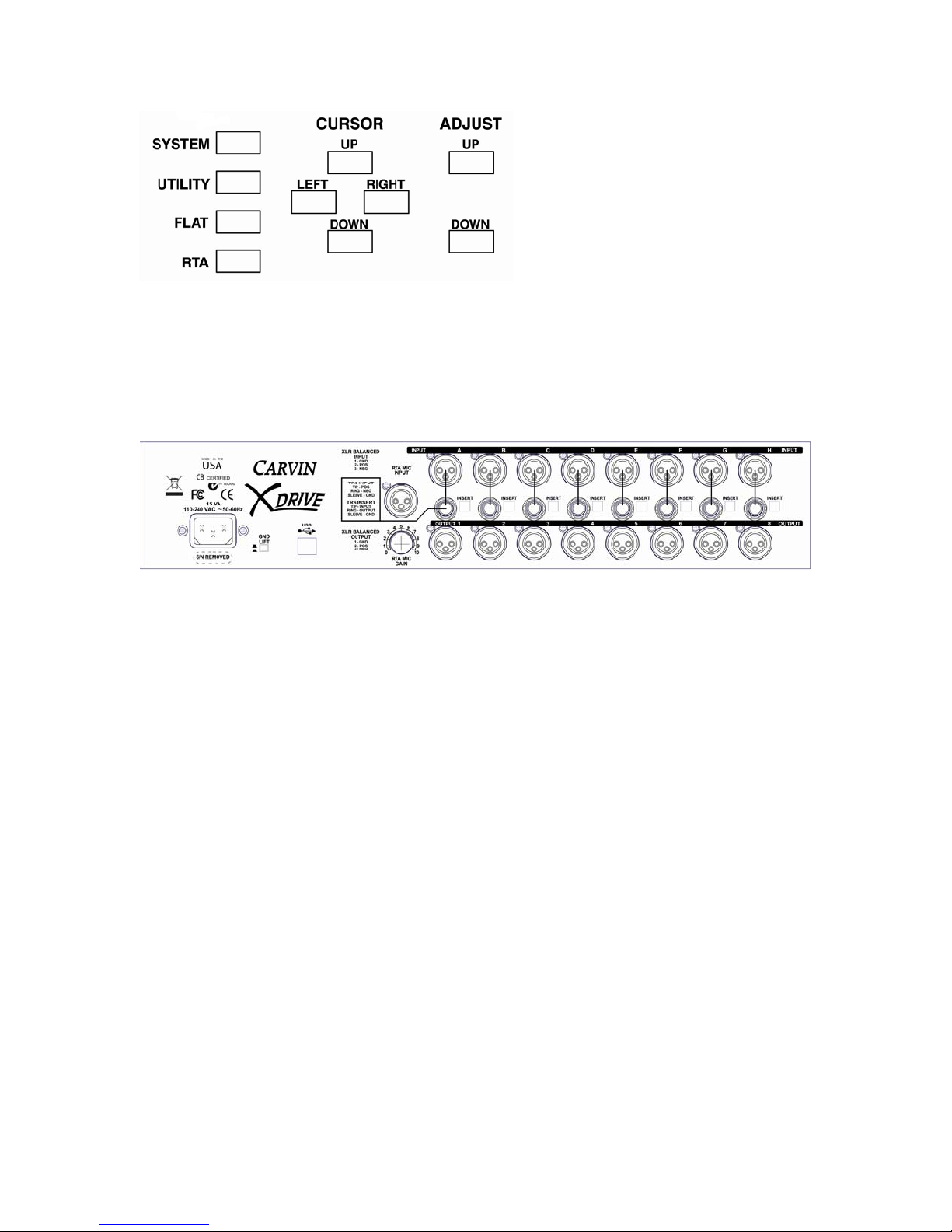
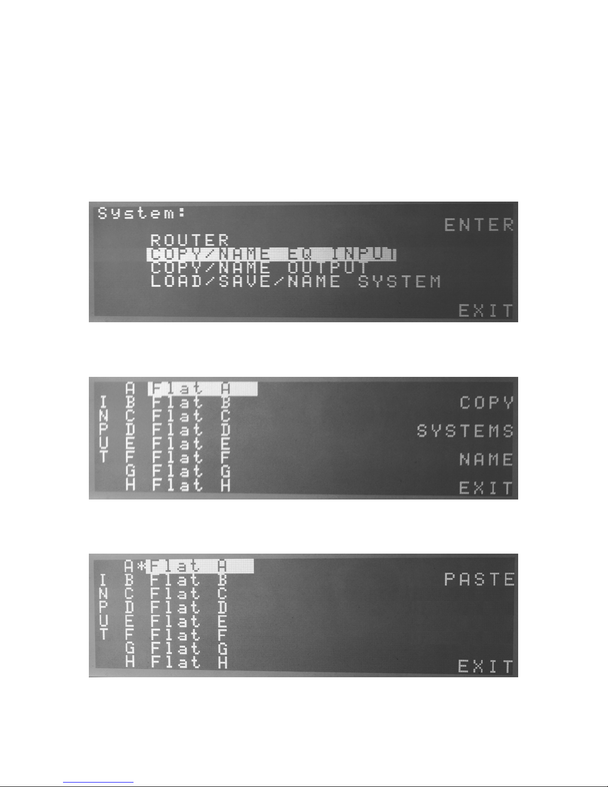
The XD88 provides a large 64x240 graphic display for easy programming. For remote
setting, use the easy to use USB PC interface – go to carvin.com/XD88 for the online
demonstration. Large memory capacity has enough storage to contain up to sixteen
complete 8x8 configurations or unlimited configurations on your PC allowing you to
keep settings for multiple loudspeakers, multi-room installs and line-arrays. Processing
offers extremely low latency, low noise with full 20-20Khz bandwidth from premium 24
BIT AD and DA converters.
The XD88 offers all the serious tools needed for a comprehensive loudspeaker
management system. Combined with 8 inputs/8 outputs, first-rate components, high order
AD DA converters, easy to use interface and a price that everyone can afford, the XD is a
product that everyone would dream of having in their rack.

2
Table of Contents:
Introduction……………………………………………………1
Table of Contents……………………………………………...2
Safety Warning………………………………………………...3
Front Panel Controls………………………………………...3-4
Rear Panel Connections……………………………………….4
Input Channels……………..………………………………….5
Graphic EQs…………………………………………...5
Output Channels……………………………………………….5
Gain……………………………………………………6
Phase…………………………………………………..6
Parametric EQs……………………………………...6-7
Low/High Cut Filters (Crossover)…………………….7
Limiter……………………………………………........8
Delay…………………………………………………..8
System Menu………………………………………………….9
Router (Matrix Mixer)………………………………...9
Saving/Copying/Re-Naming Channels…………...10-12
Saving/Loading/Re-Naming Systems……....………..13
Utility Menu………………………………………………….13
Pink Noise Generator………………………………...13
Delay Units (ft,m)…………………………………....14
Serial Control………………………………………...14
Real Time Analyzer (RTA)…………………………………..15
Sample Setups…………………………………………….15-16
Specifications…………………………………………………17

3
SAFETY
Before using, read these instructions.
WARNING – TO REDUCE THE RISK OF FIRE OR SHOCK DO NOT EXPOSE
TO RAIN OR MOISTURE.
DO NOT REMOVE COVER – NO USER SERVICEABLE PARTS INSIDE
Do not defeat the safety ground on the AC plug
Protect the power cord from being walked upon or pinched at the plug
Unplug when not in use for a long time
This equipment has been tested and found to comply with international safety
standards
Front Panel Controls:
There are 60 frequency fader UP/DOWN buttons that represent each of the sliders for a
30 band graphic EQ, or to quickly set a frequency for another function.
Each INPUT and each OUTPUT has its own select button as well as a MUTE button for
each OUTPUT.

4
System controls: SYSTEM, UTILITY, FLAT, RTA (These also act as software buttons
when in SYSTEM and UTILITY menus.)
CURSOR controls: UP, DOWN, LEFT, RIGHT
ADJUST controls: UP, DOWN
Rear Panel Connections:
The XD88 X-Drive has 8 XLR inputs and 8 XLR outputs. There are also 8 ¼”
Unbalanced inputs, that with the press of a switch, can be used to connect straight to the
Inserts (Input/Output un-balanced) in one jack. This is not an insert into the DSP, but a
single jack connection to plug into the “insert” of a mixer. The Tip connection is the
INPUT and the Ring connection is the OUTPUT.
There is a XLR Microphone Input for the Real Time Analyzer (RTA). This has Phantom
power for using condenser microphones.
There is a USB type B jack for connection to a PC for remote control using Carvins
XD88 control software.
The power receptical is a standard IEC that will take from 90 – 250 VAC as a power
source. The ground connection on a power cord should never be removed. There is a
Ground Lift switch next to the power jack to help in solving ground loop problems.

5
INPUTS:
When the unit is first turned on, the Input A EQ screen will display. To adjust the Gain
(volume) of the selected input use the Adjust UP/DOWN buttons. The range is 0db at
maximum to -32db at minimum. To adjust the ‘faders’ press any of the 60 fader up/down
buttons to adjust that frequency from +12.0dB to -12.0dB. To get back to adjusting the
Gain of this channel press the Input select button again. To edit any of the other Inputs
press that channels Input Select button. Pressing any INPUT select button from any
screen, except when in the SYSTEM or UTILITY menus, will bring up that channels
screen. When you change from one INTPUT to another all the changes are saved in
memory.
The FLAT button will reset all the parameters on a channel to the ‘Flat’ (0 or OFF)
settings except for the GAIN.
OUTPUTS:
The Outputs will all be muted on power up and each must be un-muted individually using
the Output Mute buttons. A muted channel is indicated by the PEAK (Red LED) staying
on constantly and no signal light on that Output channel.
To edit the output parameters, press the output select button for the desired channel. Use
the CURSOR UP/DOWN/LEFT/RIGHT buttons to move the cursor to the parameter you

6
wish to change. The values can then be changed with the Adjust UP/DOWN buttons.
Pressing an OUTPUT select button from any screen, except when in SYSTEM or
UTILITY menus, will bring up that channels screen. When you change from one
OUTPUT to another, all the changes are saved in memory.
GAIN and PHASE:
The Gain has the same range as the Input. This is used to turn down levels to individual
components in a system (i.e.: tweeters, mid-range drivers, sub-woofers).
The Phase is either IN or OUT 180 degrees. This can be used to adjust the phase of
individual components in a multi-component system (2-way, 3-way, 4-way systems) or to
correct a miss-wired speaker.
Parametric EQ:
The 4 Parametric EQs on the Outputs are full range. The frequency can be adjusted 2
ways. One is to move the cursor to the frequency position and use the Adjust UP/DOWN
buttons, or the other is when any of the PEQ parameters are selected, press one of the
frequency fader buttons to select that frequency into the PEQ frequency parameter. The
PEQ gain has the same range as the EQ faders of +12.0dB to -12.0dB. The bandwidth of
the PEQ can be adjusted from very narrow 0.04 octaves to extremely wide 3.0 octaves.

7
Figure 1 above is a +12dB boost, 1kHz filter of varying bandwidth/oct. In the center (1)
is the 0.04 minimum setting. Next are settings of 0.32oct (2), 0.64oct (3), 1.00oct (4),
2.00oct (5) and 3.00oct (6). 0.04oct has a narrow slope for picking out specific
frequencies. 0.32oct is equal to the fader bandwidth on a normal 30 band eq which is 1/3
octave. The maximum setting of 3 octaves has a bandwidth of 9 faders with a broad
slope.
LOW CUT and HIGH CUT FILTERS:
The Low Cut Filter can be adjusted with 3 different filter types (Butterworth, Bessel and
Linkwitz-Riley) from 1st to 6th order. The Frequency of the filter can be selected the same
way the PEQs frequency can. Either the fader buttons or the Adjust UP/DOWN can be
used.
The High Cut Filter can be adjusted the same as the Low Cut Filter.

8
LIMITER:
The Limiter has a maximum threshold level of +18.0dB, which is the maximum output,
down to -14.0dB with a Release Time from 0.02 Seconds to 5.0 Seconds. The Limiter is
used to control peaks to protect amplifiers and speakers, to maintain an average level
which prevents distortion and clipping.
DELAY:
The Delay is adjustable from 0 to 456 milliseconds (0-507ft.). The delay can be adjusted
in large (mS) and small (uS), Meters/mm or Feet/Inches. To change between Feet or
Meters, press the UTILITY button to enter the Utility menu. Press the CURSOR DOWN
button to select the DELAY parameter and press the UTILITY button to toggle between
FEET or METERS. Press the EXIT (RTA button) to return back to the INPUT/OUTPUT
screens.
The FLAT button will reset all the parameters on a channel to the ‘Flat’ settings except
for the GAIN.

9
SYSTEM MENU:
Pressing the SYSTEM button will open up the SYSTEM menu. Pressing EXIT (RTA
button) will exit back out to the INTPUT/OUTPUT screens. Use the CURSOR
UP/DOWN buttons to move through the menu.
ROUTER (MATRIX MIXING):
The stock Routing configuration of the Inputs to Outputs is Input A to Output 1, Input B
to Output 2, etc. If you need to make changes for 2-way, 3-way or summing Left and
Right to Mono-Sub type setups, you press the SYSTEM button to get to the SYSTEM
screen. Press the SYSTEM button again to enter the ROUTER screen. Each horizontal
line is an Output (1-8) and the vertical columns are for each Input. So the upper left ‘A’
represents Input A routed to Output 1. To select a line to edit use the CURSOR
UP/DOWN buttons or press the Output select button to directly select that Output line,
then press the Input buttons to turn on or off the associated Input. Once the router is
configured for your setup, press the RTA button to Exit out of the SYSTEM menus.

10
Saving/Copying/Re-Naming channels:
The channels on the local system are always saved when changing from one channel to
the next or when entering the SYSTEM or UTILITY menus.
The channel names can be changed when in the COPY/NAME screen. Press NAME
(FLAT button) and an asterisk will appear next to the channel you are modifying. Use the
CURSOR LEFT/RIGHT to move to the position you want to change and use any of the
UP/DOWN buttons to scroll through the different characters.
Use the CURSOR UP/DOWN buttons to select the menu item wanted. Press ENTER
(SYSTEM button), to open into the selected item.
Select the channel that you wish to copy to a new location and press COPY (SYSTEM
button).
The channel to be copied will be marked with an asterisk ‘*’.

11
Select the new location you wish to PASTE the copied channel to and press the PASTE
(SYSTEM button).
An alternative is to copy a channel from a saved system in memory. To do this, press
SYSTEMS (UTILITY button), from the copy screen to open up a system from memory.
Select the system that contains the channel you want to copy by pressing OPEN
(SYSTEM button). Any time you wish to go back a step to choose a different system or
channel, press BACK (FLAT button). To exit to the SYSTEM menu screen press EXIT
(RTA button).

12
Once the system from memory is opened the copy procedure is the same as copying a
local channel. Press COPY (SYSTEM button) to select the channel to copy and it will be
marked with the ‘*’.
Select the channel you wish to copy into and press PASTE (SYSTEM button).
The procedure for copying the Output channels is the same as the Inputs.

13
SAVE/LOAD SYSTEMS:
To Save, Load or Re-Name a system ENTER (SYSTEM button) in this menu.
Pressing the LOAD (SYSTEM button) or SAVE (UTILITY button) will either load the
selected system into the local memory or save the local memory into the selected system.
The local system is what is in memory when the unit is turned on.
UTILITY:
The first entry in the Utility menu is the Noise generator. This produces a Pink Noise
signal to help set up your system. To toggle the NOISE ON or OFF, press the ENTER
(UTILITY button). Because the Pink noise is inserted into all the Inputs when NOISE is
turned on, all the Outputs will be muted. You can then un-mute each component/Output

14
you wish to hear. It is a good idea to turn down the amplifiers connected to the
OUTPUTS. Bring them up slowly until the desired level of PINK NOISE is reached.
The second entry in the Utility menu allows you to set the desired units of Delay. This
will be shown on the Output screen. Once again pressing ENTER (UTILITY button) to
toggle between Feet or Meters.
The last entry on the Utility menu enters the Serial Control mode. This is used when
connected through the USB cable to a PC running the Carvin XD88 control software.
Once the XD88 is connected to a PC via the USB cable, press ENTER (UTILITY button)
to set the unit in remote control mode. Press the RTA button to exit the Remote control
mode. Now you can control your XD88 from the PC. The maximum cable length for the
USB connection is 16 feet 5 inches or 5 Meters.

15
RTA:
The RTA is selected by the RTA button when not in the SYSTEM or UTILITY menus.
To freeze the screen temporarily, press and hold the RTA button. To select one of the 8
Outputs or the RTA MIC, move the cursor with the LEFT/RIGHT buttons until the
channel is selected. Use the UP/DOWN buttons to select a different channel. By pressing
one of the 60 fader buttons, you can select a frequency band to highlight. This will show
the frequency and level of the highlighted band on the second line of text. To exit the
RTA, press any of the INPUT, OUTPUT, SYSTEM or UTILITY buttons.
The RTA has a range from 0dB (digital-fullscale) to -70dB which is +20dB (analogue) to
-50dB at the Output jack. To change the size of the window use the CURSOR
LEFT/RIGHT buttons to select either TOP or WNDW (window). The window sizes are
60dB, 30dB and 15dB to allow closer viewing of the signal. For the 60dB window the
values are 0 and -10dB so the minimum signal you can view is -70dB. The 30dB window
will move down in steps of 15dB and the 15dB window will move down in steps of 5dB.
Typical setups:
A: 8 graphic eqs straight through for full range left-right mains and 6 monitors.
Router:

16
B: Mono 3-way mains and 5 full range monitors.
Router:
OUTPUT1: Highs – LF= BUT12 1.03kHz HF = OFF
OUTPUT2: Mids – LF= BUT12 311.2 Hz HF = BUT12 1.03kHz
OUTPUT3: Lows – LF= OFF HF = BUT12 311.2 Hz
C: 2-way Stereo Mains with Mono Sub and 3 full range monitors.
Router:
OUTPUT1: Highs – LF= BUT12 1.03kHz HF = OFF
OUTPUT2: Lows – LF= BUT12 100 Hz HF = BUT12 1.03kHz
OUTPUT3: Highs – LF= BUT12 1.03kHz HF = OFF
OUTPUT4: Lows – LF= BUT12 100 Hz HF = BUT12 1.03kHz
OUTPUT5: Subs – LF= BUT6 32 Hz HF = BUT12 125 Hz
D: Four 2-way monitors.
Router:
OUTPUT1: Highs – LF= BUT12 1.03kHz HF = OFF
OUTPUT2: Lows – LF= OFF HF = BUT12 1.03kHz

17
SPECIFICATIONS:
INPUTS:
Connector Female XLR & ¼” TRS 10kOhm electronically balanced
Maximum Input +18 dBu
Digital Controls:
Gain 0dB to -32dB in 0.2dB steps
EQ 30 Band Graphic 25Hz to 20kHz, +/- 12dB in 0.1dB steps
OUTPUTS:
Connector Male XLR 150 Ohms electronically balanced
Maximum Output +18 dBu
Dynamic Range 120dB unweighted 22Hz – 22kHz
Frequency Response 20Hz – 20kHz
Distortion (THD) <0.005%, 20Hz – 20kHz @+10dBu
Digital Controls
Gain 0dB to -32dB in 0.2dB steps
Phase 0 or -180 degrees
Parametric EQ 20Hz to 20.5kHz, +/- 12dB in 0.1dB steps, 0.04 to 3.0 octaves(Q)
in 0.04 steps.
Limiter +18dB to -14dB(at Output) hard limiting Release time 0.02 to 5.0
seconds
Crossover Filters 6, 12, 18, 24, 48dB/oct, Butterworth, Bessel and Linkwitz-Riley
Delay 0-456.939mS in 21uS steps (0-507ft 8.52in. in 0.28in steps or 0-
152.313 meters in 7mm steps)
System Processing:
Multi DSP 48kHz 24 bit
A2D Converters 114dB 24 bit
D2A Converters 120dB 24 bit
General:
Dimensions 19”W x 3.5”H x 8”D (483mm x 89mm x 204mm)
Weight 7.3 lbs (3.31 kgs)
Power 90-250 VAC, 50/60Hz standard IEC receptical
Table of contents
Other CARVIN Recording Equipment manuals
Popular Recording Equipment manuals by other brands

IonSense
IonSense DART-Thermo LTQ manual

ADS Technologies
ADS Technologies INSTANT MUSIC FOR MAC - quick guide

Cedar
Cedar DNS1500 owner's manual

Advanced
Advanced Axis AV-V70-KIT installation instructions

Ultra electronics
Ultra electronics HYPERSPIKE HS-18 RAHD Operation and maintenance manual

Fiberplex
Fiberplex FOI-6010 user manual