Installation –1.4
Safety Cabinets are sophisticated items of equipment containing delicate filters which require
expertise in their safe handling and installation into laboratories.
For exhaust type safety cabinets the exhaust ductwork route should ideally be surveyed and
ductwork installation be carried out by qualified engineers as it forms an integral part of the
system relating to the overall performance of the cabinet and is required to conform to various
safety standards.
A poorly installed cabinet may compromise the protection provided to both personnel and
work being handled and may present a hazard to other occupants of the building and the
public.
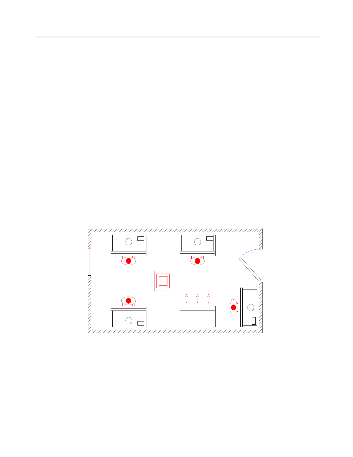
·Make-up Air
It is important that any make-up air compensating for the air exhausted from the safety
cabinet does not cause draughts to the discomfort of the laboratory staff or detriment of the
cabinet performance.
Air supply diffusers should be positioned more than 1500mm away from the front of the safety
cabinet and have a maximum velocity of no more than 0.30m/sec.
·Commissioning
When any safety cabinet is installed, it is necessary to carry out a number of commissioning
checks in order to ensure it is fully operational and that the performance on site satisfies the
current standard BS EN 12469:2000. This includes measuring the airflows, testing the HEPA
filters with a suitable challenge aerosol and a KI Discus Test (operator protection test) to assess
the containment of the cabinet.
CAS employs a team of fully trained installation and commission engineers to carry out all work
necessary. This ensures that all new safety cabinets operate to the desired performance.
·Site Surveys
If you have any queries regarding the siting of your safety cabinets we will be only too pleased
to arrange a site survey by one of our regionally based technical support staff.
·Periodic Maintenance & Servicing
To maintain safety cabinets at their optimum level of performance and to ensure lifetime
operation, regular servicing is necessary. CAS provides a full servicing and maintenance scheme
tailored to suit your individual needs. For more information on this please contact our service
department on 0161-655-8860.