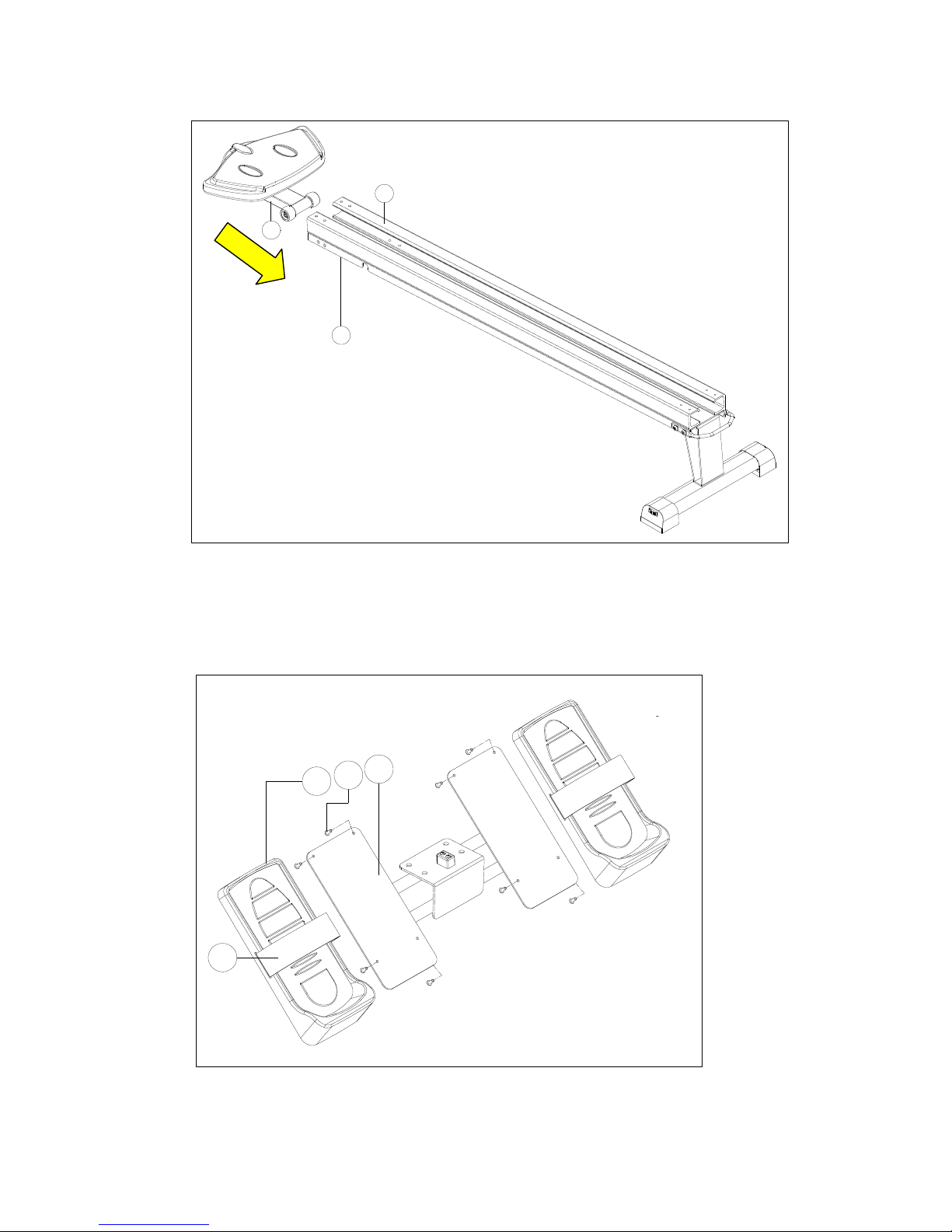
Casall R-600 User manual

Instruction Manual
ROWER MACHINE R-600

KIT TOOL & SCREW SET - List
(Pedal Wrench)
Allen Key(1)
Screwdriver (1)
R600
I-3 Screw M5*12 (8)
I-2 Curved washer for ?8*?19*2T bolt(8)
I-1 Allen Bolt M8x16mm¡ ]8¡ ^
I-4 Screw M5*10 (4)

Assembly Instruction
D-16
D-15
K-1
I-1
I-2
J
I-3
I-1 I-2
J-3
N-6
I-4
D-13
D-14
D-13
D-14
J-5
O
D-35
D-37
N-4
N-5
N-3
N
M-L
M-R
K

Exploded Drawing
A
A-1
B
B-2
B-3
B-4
B-5 B-1
DD-2
D-1
D-3D-5
D-4
D-6
D-7 D-8 D-9
D-10
D-11
D-14 D-13
D-16
D-15
D-18
D-17L
D-19
D-20L D-21
D-20R
D-17R
D-23
D-22
D-27 D-26 D-25 D-24 D-29
D-28
E
E-1
E-2
E-3
E-4
E-5
E-6
E-7
F
F-1
F-2
F-3
F-4
F-5
F-6
F-7
F-8
F-9
F-10 G
G-1
G-2
G-3
G-4
G-5
G-6 G-7 G-8 G-9
G-10
H
H-1
H-2
H-3
H-4
H-5
H-6
H-7
H-8
H-9
H-10
H-11
H-12
H-13
H-14
H-15
H-16
H-17
H-18
H-19
H-20
I-1 I-2
I-3
JJ-1
J-2
J-3
KK-2 K-3
K-1
I-1
I-2
I-4
D-13
D-14
M-L M-1
M-R M-2 M-3
N
N-1 N-2
N-3 N-4 N-5 N-6
D-30
J-4
J-5
D-31 O
D-32
D-33
D-34 D-35
D-36
D-37
D-38
D-39
D-40 D-12
C-7
C-8
C-11
C
L
L-1
L-3 L-2
L-4 L-5 L-6 L-7
L-8 L-9 L-10
L-11
L-12
L-13
L-14
C-6
C-1
C-2
C-4
C-3C-9 C-10
C-5
C-12
C-13
D-35

Parts List ROWER MACHINE
No.
Description
Quantity
A
COMPUTER
1
SET
A-1
SCREWS FOR FIXING COMPUTER
4
PCS
B
SUPPORTING TUBE FOR BRACKET
1
PCS
B-1
BRACKET FOR FIXING COMPUTER
1
PCS
B-2
SCREWS M6xP1.0x57L
2
PCS
B-3
FIXING CAP
4
PCS
B-4
FLAT WASHER φ6xφ16x1t
2
PCS
B-5
NYLON NUT M6
2
PCS
C
BRACKET FOR ROLLER
1
SET
C-1
DRIVING PULLEY
1
SET
C-2
ROLLER
1
SET
C-3
SCREWS 3/8"x54mm
1
PCS
C-4
SCREWS M6x50L
1
PCS
C-5
NYLON NUT 3/8"x7t
1
PCS
C-6
NYLON NUT M6
1
PCS
C-7
SPRING WASHER 8*φ14*2T
2
PCS
C-8
FLAT WASHER φ8*φ19*2T
2
PCS
C-9
BUSHING φ10xφ14x8mmL
2
PCS
C-10
BUSHING φ6xφ9x6mmL
4
PCS
C-11
HEXSGONAL SCREWS M8xP1.25x16L
2
PCS
C-12
FLAT WASHERφ10*φ18*1T
1
PCS
C-13
FLAT WASHERφ6*φ12*1T
1
PCS
D
MAINFRAME
1
SET
D-1
CAP FOR FRONT STABLILZER(LEFT)
1
PCS
D-2
CAP FOR FRONT STABLILZER(RIGHT)
1
PCS
D-3
SUPPORTING CAP(LEFT)
1
PCS
D-4
SUPPORTING CAP(RIGHT)
1
PCS
D-5
ADJUSTING CAP
2
PCS
D-6
HEXAGONAL SCREW 3/8"-16x3t
2
PCS
D-7
TRANSPORATION WHEEL
2
PCS
D-8
C-TYPE RING φ8
2
PCS
D-9
SPEEDY NUT M8
2
PCS
D-10
SENSOR BOX
2
SET
D-11
SCREWS M4x10L
2
PCS
D-12
SCREWS M5x12L
3
PCS
D-13
SCREW M8*P1.25*16L(6m/m)
8
PCS
D-14
FLAT WASHER φ8*φ19*2T
8
PCS
D-15
FRONT CAP FOR SLIDER
1
PCS
D-16
SCREW M5x10L
3
PCS
D-17L
LEFT COVER(LOWER)
1
PCS
D-17R
RIGHT COVER(LOWER)
1
PCS
D-18
SCREW 3/16"(#10)x3/4"
2
PCS
D-19
SCREW M4x50L
3
PCS
D-20L
SIDE COVER(LEFT)
1
PCS
D-20R
SIDE COVER(RIGHT)
1
PCS

-1-
D-21
SCREW M4x8L
12
PCS
D-22
CONNCTION PIN OF COVER
1
PCS
D-23
SCREW M4x12L
10
PCS
D-24
DIVERSION OF FAN
3
PCS
D-25
POLE
2
PCS
D-26
FIXING SOCKET OF FAN
6
PCS
D-27
SCREW M3x8
12
PCS
D-28
COVER OF FAN
1
PCS
D-29
FAN COVER
1
PCS
D-30
SCREW M5x8L
1
PCS
D-31
DC WIRE
1
SET
D-32
SCREW M5x8L
4
PCS
D-33
CONNECTION BAR
1
PCS
D-34
DOWN COMPUTER CABLE
1
PCS
D-35
PULSE WIRE FOR WIRELESS RECEIVER
1
PCS
D-36
UPPER COMPUTER CABLE
1
PCS
D-37
WIRELESS RECEIVER FOR PULSE
1
PCS
D-38
BRACKET FOR COMPUTER
1
PCS
D-39
FLAT WASHERS 5xφ10x1t
3
PCS
D-40
SPRING WASHERSφ5
3
PCS
E
HANDLABAR
1
SET
E-1
PLASTIC WASHER φ45xφ32.2x0.5t
2
PCS
E-2
BUSHING φ32.2xφ44.3x29L
1
PCS
E-3
HEXAGONAL SCREW M6xP1.0x5L
2
PCS
E-4
BUSHING OF FOAM φ32.2xφ44.3x10L
1
PCS
E-5
FOAM GRIP
2
PCS
E-6
CAP FOR HANDLEBAR
2
PCS
E-7
INKLE
1
PCS
F~F-9
FLYWHEEL SET
1
SET
F-10
BELT
1
PCS
G~G-10
IDER WHEEL SET
1
SET
H~H-20
SPRING BOX
1
SET
I-1
SCREW M8*P1.25*16L(6m/m)
8
PCS
I-2
FLAT WASHER φ8*φ19*2T
8
PCS
I-3
SCREW M5xP0.8x12L
8
PCS
I-4
SCREW M5*P0.8*10L
4
PCS
J
PEDAL HOLDER
1
SET
J-1
STOPPER
1
PCS
J-2
SCREW M5x25L
2
PCS
J-3
PEDAL
2
PCS
J-4
PAD OF PEDAL
2
PCS
J-5
FIX BAND OF PEDAL
2
PCS
K
ROLLING SLIDER
1
SET
K-1
SADDLE
1
PCS
K-2
ROLLER (PU WHEEL)
4
SET

-2-
K-3
NLYON NUT M8
4
SET
L~L-14
MAGNETIC BRACKET & GEAR BOX
1
SET
M-L
LEFT SLIPPERY RAIL
1
PCS
M-R
RIGHT SLIPPERY RAIL
1
PCS
M-1
SCREW M5x30L
2
PCS
M-2
NYLON NUT M5
2
PCS
M-3
STOPPER FOR SILDER
1
PCS
N
REAR STABILIZER
1
SET
N-1
ADJUSTING CAP
2
PCS
N-2
SCREW 3/16"(#10)x3/4"
2
PCS
N-3
CARRY BAR FOR TRANSOPORTATION
1
PCS
N-4
FLAT WASHER φ8xφ16x2t
4
PCS
N-5
SCREW M8xP1.25x20L(6m/m)
4
PCS
N-6
REAR COVER FOR SLIDER
1
PCS
O
AC ADAPTOR
1
SET

-3-
Step 1
1. Insert the Rear Support (N), and then attach the Rear Support to the Slippery Rail (M-L,M-R) using
M8xP1.25x20L Bolt (N-5), Flat Washers (N-4) and Carry Bar (N-3).
Step 2
1. Attach the Seat (K-1) and the Rolling Slider ( K) with M8*P1.25*16L Bolt (I-1) and Flat Washers (I-2)
?
M-L
M-R
N-4
N-5
N-3
N
K-1
I-1
I-2
K
?

-4-
Step 3
1. Slide the Seat with slider (K) onto the Slippery Rail (M-L, M-R).
Step 4
1. Attach the Pedal with fix band (J-3 & J-5 ) to the pedal support ( J ) with Screws (I-3).
I-3
J-3
J-5
J
?
?
K
M-L
M-R

-5-
Step 5
1. Insert the Pedal Holder (J) and attach the Slippery Rail (M-L, M-R) with M8*P1.25*16L Bolt (I-1) and Flat
Washers (I-2).
Attention! When you fix the 4 screws of the pedal holder of to the slider, the 4 screws cannot be
fixed too tightly at the same. The reason is that the size of the screw hole is bigger than the screw.
If you tighten them too much the slider will not be paralleled to the rail and the saddle will not slide
smoothly.
Step 6
1. Attach the Rear Cover (N-6) over the Slippery Rail (M-R/L) using of Screw (I-4).
?
I-1 I-2
J
M-L
M-R
?
N-6
I-4
M-L
M-R

-6-
Step 7
1. Insert the Slippery Rail (M-l , M-R) and fix it to the Main Frame (D) with M8*P1.25*16L Bolt (D-13) and
Flat Washers (D-14).
2. Finally, attach the Cover (D-15) over the Main frame (D) using of M5x10LWasher (D-16).
3. Connect the Pulse Wire (pt.D-35) and the Wireless Receiver Wire (pt. D-37). The wires can
be found below the main frame.
?
D-16
D-15
D-13
D-14
D-13
D-14
O
D
D-35
D-37

INSTRUCTIONAL MANUAL FOR CASALL R600 CONSOLE
[DISPLAY FUNCTION:]
[ BUTTON FUNCTION: ]
ITEM
DESCRIPTION
SPM
‧Strokes per minute
‧Display range 0~999
Time/500m
‧Workout time display during rowing.
‧Display range 0:00~99:59
‧*Computer will display the time needed to row 500 meters according to current speed
every 6 seconds.
METERS
‧Rowing distance
‧Display range0~99999
CALORIES
‧Burned calories during rowing.
‧Display range 0~9999
STROKES
‧Number of completed rowing strokes.
‧Display range: 0~9999
‧Scan every 6 seconds with Total Strokes.
‧*Stroke count will be lost if power is out (adaptor unplug).
PULSE
‧Pulse bpm during rowing.
‧Display range 0-30~240。
ITEM
DESCRIPTION
Up
‧Setting selection.
‧Increase resistance level.
Down
‧Setting selection.
‧Decrease resistance level.
ENTER
‧Confirm setting or selection.
Reset
‧Hold on pressing for 2 seconds, computer will reboot.
‧Clear setting value.
‧Return to main menu after finishing a workout.
Start/ Stop
‧Start or Stop rowing training.
Recovery
‧Test heart rate recovery status.

-1-
[OPERATION]
POWER ON
Plug in power supply, computer will power on and display all segments on LCD for 2 seconds. Enter into
clock and calendar setting mode.
After 4 minutes without rowing or pulse input, console will enter into power saving mode. And display
clock, calendar and room temp.
Manual Mode:
Adjust resistance during workout manually.
1. Press START key in main menu may start workout in manual mode.
2. Press UP or DOWN to select Manual mode and press ENTER to confirm.
3. Press UP or DOWN to set RESISTANCE LEVEL, TIME(or Meters), STROKES and CALORIES, and press
ENTER to confirm. (User can ONLY choose between time and meter. Both cannot be set at the same
time.)
4. Press START/STOP key to start workout. Press UP or DOWN to adjust resistance level.
5. When targeted workout value counts down to 0, the alarm from the console will sound and workout
stops.
6. Press START/STOP key to pause workout. Press RESET to return to main menu.
Program Mode:
Choose a preset workout program.
1. Press UP or DOWN to select Program mode and press ENTER to confirm.
2. Press UP or DOWN to select a specific preset workout program (P1~P12) and press ENTER to confirm.
3. Press UP or DOWN to set RESISTANCE LEVEL, TIME(or Meters), STROKES and CALORIES, and press
ENTER to confirm. (User can ONLY choose between time and meter. Both cannot be set at the same
time.)
4. Press START/STOP key to start workout. Press UP or DOWN to adjust resistance level
5. When targeted workout value counts down to 0, the alarm from the console will sound and workout
stops.
6. Press START/STOP key to pause workout. Press RESET to return to main menu.

-2-
.
H.R.C. Mode:
Target a heart rate for the workout.
1. Press UP or DOWN to select H.R.C. mode and press ENTER to confirm.
2. Press UP or DOWN to set AGE, and press ENTER to confirm.
3. Press UP or Down to select 55%.75%.90% or TA (Target heart rate.). (default: 100).
*Formula: (220-Age) X ___%
*Example: Age 25 choosing 75%, you will target your heart rate to (220-25) x 75%= 146/min
4. Press UP or DOWN to set RESISTANCE LEVEL, TIME(or Meters), STROKES and CALORIES, and press
ENTER to confirm. (User can ONLY choose between time and meter. Both cannot be set at the same
time.)
5. Press START/STOP key to start workout.
6. When targeted workout value counts down to 0, the alarm from the console will sound and workout
stops.
7. Press START/STOP key to pause workout. Press RESET to return to main menu.

-3-
Race Mode:
Race against the computer.
1. Press UP or DOWN to select Race mode and press ENTER to confirm.
2. Press UP or DOWN to preset Challenge level and press ENTER to confirm. (Total level =15, Default
time= 0:30 TIME/500M, Default distance=500M)
3. Press START/STOP key to start workout. Press UP or DOWN to adjust resistance level.
4. When PC or User finishes the rowing distance, computer will stop and show PC win or User win.
5. Press START/STOP key to pause workout. Press RESET to return to main menu.
USER Mode:
Preset your own workout profile.

-4-
1. Press UP or DOWN to select USER mode and press ENTER to confirm.
2. Press UP or DOWN to set resistance level of each column, and press ENTER to set the next resistance
column.
(Total resistance column = 16)
3. Hold on pressing MODE to finish or quit setting
4. Press UP or DOWN to set RESISTANCE LEVEL, TIME(or Meters), STROKES and CALORIES, and press
ENTER to confirm. (User can ONLY choose between time and meter. Both cannot be set at the same
time.)
5. Press START/STOP key to start workout. Press UP or DOWN to adjust resistance level.
6. When targeted workout value counts down to 0, the alarm from the console will sound and workout
stops.
7. Press START/STOP key to pause workout. Press RESET to return to main menu.
Recovery Mode
Monitor heart rate recovery status.
1. When pulse value displays on the computer (wear chest strap), press RECOVERY button.
2. TIME shows "0:60" (seconds) and begin countdown.
3. Computer will show heart rate recovery levels from F1 to F6 after countdown.
*Please see the F level chart below to determine the recovery level.
Trouble shooting:
E-2:Check if cables were well connected or damaged.

-5-
Attention! All preset data will be lost when unplug the power (adaptor) from the
"machine".
The console is designed for single workout usage only.


-1-
Table of contents
Other Casall Home Gym manuals